manuals.online logo
Brands
  1. Home
  2. •
  3. Brands
  4. •
  5. Renson
  6. •
  7. Window Blind
  8. •
  9. Renson Outdoor Loggia Safety guide

Renson Outdoor Loggia Safety guide

Other manuals for Outdoor Loggia

4

Other Renson Window Blind manuals

Renson Detecto Rensonmotor Instruction Manual

Renson

Renson Detecto Rensonmotor Instruction Manual

Renson Fixscreen Minimal Guide

Renson

Renson Fixscreen Minimal Guide

Renson Somfy LS40 User manual

Renson

Renson Somfy LS40 User manual

Renson Slidefix User manual

Renson

Renson Slidefix User manual

Renson Fixscreen 100 Solar User manual

Renson

Renson Fixscreen 100 Solar User manual

Renson Fixscreen 150 (F) User manual

Renson

Renson Fixscreen 150 (F) User manual

Renson Panovista User manual

Renson

Renson Panovista User manual

Renson Outdoor Loggia Safety guide

Renson

Renson Outdoor Loggia Safety guide

Renson Fixscreen Minimal Neubau EW 7 User manual

Renson

Renson Fixscreen Minimal Neubau EW 7 User manual

Renson Fixscreen Minimal User manual

Renson

Renson Fixscreen Minimal User manual

Renson Outdoor Loggia Safety guide

Renson

Renson Outdoor Loggia Safety guide

Renson Fixscreen 100EVO Solar User manual

Renson

Renson Fixscreen 100EVO Solar User manual

Popular Window Blind manuals by other brands

Windhager PLUS 100x120 cm quick start guide

Windhager

Windhager PLUS 100x120 cm quick start guide

Rollos S-Nanorollo V2 Assembly and operating instruction

Rollos

Rollos S-Nanorollo V2 Assembly and operating instruction

IKEA KADRILJ manual

IKEA

IKEA KADRILJ manual

Teptron Move user manual

Teptron

Teptron Move user manual

rollease acmeda Easy Spring Air Assembly and installation manual

rollease acmeda

rollease acmeda Easy Spring Air Assembly and installation manual

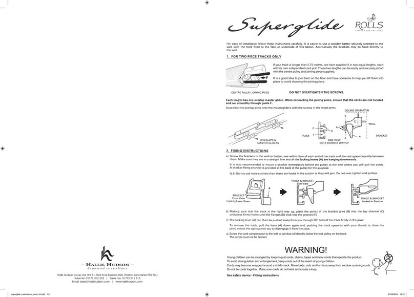
Hallis Hudson Rolls Super glide instructions

Hallis Hudson

Hallis Hudson Rolls Super glide instructions

Jysk ROGEN manual

Jysk

Jysk ROGEN manual

SOMFY 1241752 instructions

SOMFY

SOMFY 1241752 instructions

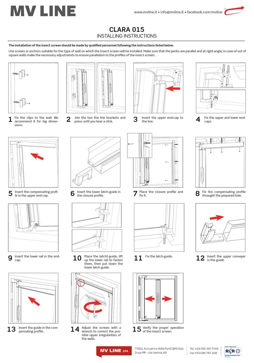
MV LINE CLARA 015 Installing instructions

MV LINE

MV LINE CLARA 015 Installing instructions

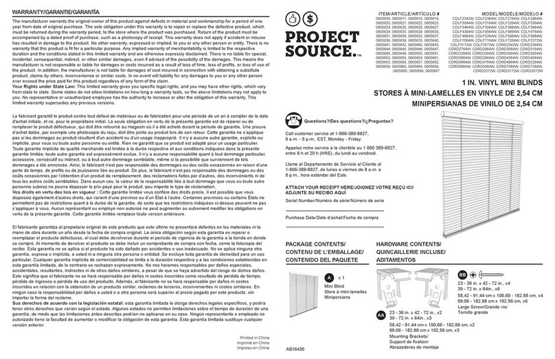
Project Source CDLF2342W quick start guide

Project Source

Project Source CDLF2342W quick start guide

Current E-WAND Installation manual and user's guide

Current

Current E-WAND Installation manual and user's guide

weinor VertiTex ZipR Maintenance Instructions and Directions for use for the end user

weinor

weinor VertiTex ZipR Maintenance Instructions and Directions for use for the end user

Roto ZAR M R4/R7 Mounting instructions

Roto

Roto ZAR M R4/R7 Mounting instructions

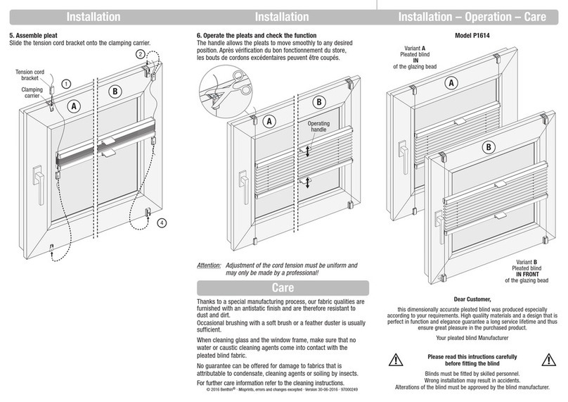
Benthin P1614 quick start guide

Benthin

Benthin P1614 quick start guide

MDT KNX Smart 55 BE-JTA5504.01 Technical manual

MDT

MDT KNX Smart 55 BE-JTA5504.01 Technical manual

Victoria M SYSTEM VS 1 Original instructions

Victoria M

Victoria M SYSTEM VS 1 Original instructions

SOMFY Movelite WT Series instructions

SOMFY

SOMFY Movelite WT Series instructions

IKEA ENJE manual

IKEA

IKEA ENJE manual

manuals.online logo
manuals.online logoBrands
  • About & Mission
  • Contact us
  • Privacy Policy
  • Terms and Conditions

Copyright 2025 Manuals.Online. All Rights Reserved.

Loggia®Handleiding - Installatie enkelvoudig schuivende panelen
Notice de montage - Installation d’un panneau coulissant simple
Montageanleitung - Installation von einzeln Schiebeläden
Manual - Installation of single sliding panels
Loggia®
2
RENSON®LOGGIA®
Please read this manual carefully before you
start. The installation of single sliding Loggia®
panels must be performed by a professional.
Overview of tools required:
• Hand saw
• Cleaning equipment
• (Electric) screwdriver
• Drill
• Spirit level
• Fixation materials
• M8 spanner
RENSON®reserves the right to make tech-
nical changes to its products without prior
notice.
RENSON®LOGGIA®
Veuillez lire attentivement ce manuel avant
de commencer l’installation. L’installation de
panneaux coulissants simples Loggia®doit
être réalisée par un professionnel.
Liste des outils nécessaires :
• Scie à main
• Matériel de nettoyage
• Visseuse / tournevis
• Perceuse
• Niveau
• Matériel de fixation
• Clé à molette M8
RENSON®se réserve le droit d’apporter des
modifications techniques à ses produits sans
avis préalable.
RENSON®LOGGIA®
Lesen Sie diese Anleitung sorgfältig durch,
bevor Sie beginnen. Die Anbringung von
einzeln Loggia®Schiebeläden muss von
einem Fachmann durchgeführt werden.
Übersicht der benötigten Werkzeuge:
• Handsäge
• Reinigungsmaterial
• Schraubmaschine/Schraubendreher
• Bohrmaschine
• Wasserwaage
• Montagezubehör
• Schraubenschlüssel M8
RENSON®behält sich das Recht vor, ohne
vorherige Ankündigung technische Änderun-
gen an seinen Produkten vorzunehmen.
RENSON®LOGGIA®
Lees deze handleiding eerst aandachtig eer
u van start gaat. Het plaatsen van enkelvou-
dig schuivende Loggia®panelen dient te
gebeuren door een vakman.
Overzicht benodigde gereedschappen:
• Handzaag
• Reinigingsmateriaal
• Schroefmachine / schroevendraaier
• Boormachine
• Waterpas
• Bevestigingsmateriaal
• Moersleutel M8
RENSON®behoudt zich het recht voor om
zonder voorafgaande kennisgeving techni-
sche wijzigingen aan haar producten aan te
brengen.
Loggia®
3
TABLE OF CONTENTS
1. Parts overview 4
2. Sawing the profiles 6
3. Fitting the stoppers and roller
assemblies 8
4. Upper rail installation options 10
4.1 Installation using wall mounting
profile 10
4.2 Installing the upper rail on the
ceiling 10
4.3 Installation with motor 12
4.4 Installation with rear rails 12
5. Lower rail installation options 14
5.1 Fitting he L-profile 14
5.2 Fitting the Flexguide Plus 14
5.3 Fitting the U-profile 16
5.4 Installation lower rail with rear
rails 16
6. Fitting the Flexguides in the Loggia
frame (optional) 18
7. Positioning the panel on the lower rail 20
7.1 Flexguide Plus + Flexguide rail
option 20
7.2 Flexguide Long + L-profile option 20
7.3 Caps + L-profile option 20
7.4 Caps in U-profile option 20
8. Hanging the panel 22
9. Motor and parts 24
9.1 Fitting the belt tensioner 24
9.2 Determining the belt length 24
9.3 Hanging the belt 26
9.4 Tensioning the belt 28
9.5 Installation of the motor 28
10. Setting the stop position of the panel 30
11. Fitting the cover (optional) 32
11.1 Fitting the cover 32
11.2 Fitting the aluminium end caps
(optional) 32
11.3 Fitting the plastic end caps
(optional) 32
12. Final checks 34
INHALTSVERZEICHNIS
1. Übersicht Teile 4
2. Sägen der Profile 6
3. Anschlag- und Rollsysteme anbringen 8
4. Montagemöglichkeiten der oberen
Schiene 10
4.1 Montage mit Wandmontageprofil 10
4.2 Montage der oberen Schiene an
der Decke 10
4.3 Montage mit Motor 12
4.4 Montage mit dahinterliegenden
Schienen 12
5. Montagemöglichkeiten der unteren
Schiene 14
5.1 Anbringen des L-Profils 14
5.2 Anbringen des FlexguidePlus 14
5.3 Anbringen des U-Profils 16
5.4 Montage die unteren Schiene mit
dahinterliegenden Schienen 16
6. Flexguide in den Loggia-Rahmen
montieren (Option) 18
7. Positionierung des Ladens auf der
unteren Schiene 20
7.1 Option Flexguide Plus +
Flexguide-Schiene 20
7.2 Option Flexguide Lang + L-Profil 20
7.3 Option Kappen + L-Profil 20
7.4 Option Kappen in U-Profil 20
8. Aufhängen des Ladens 22
9. Motor und Teile 24
9.1 Platzieren von Riemenspanner 24
9.2 Riemenlänge bestimmen 24
9.3 Aufhängen des Riemens 26
9.4 Spannen des Riemens 28
9.5 Motoreinbau 28
10. Anschlagposition des Ladens festlegen 30
11. Anbringen der Abdeckkappe (Option) 32
11.1 Anbringen der Abdeckkappe 32
11.2 Anbringen der Aluminium-
Endkappen (Option) 32
11.3 Anbringen der Endkappen aus
Kunststoff (Option) 32
12. Kontrolle 34
TABLE DES MATIERES
1. Liste des composants 4
2. Découpe des profils 6
3. Pose des arrêts et des chariots 8
4.
Possibilités de montage du rail supérieur
10
4.1 Montage avec profil de fixation
murale 10
4.2 Montage du rail supérieur au
plafond 10
4.3 Montage avec moteur 12
4.4 Montage d’une Loggia avec rails
sous-jacents 12
5. Possibilités de montage du rail inférieur 14
5.1 Pose du profil en L 14
5.2 Pose du Flexguide Plus 14
5.3 Pose du profil en U 16
5.4 Montage rail inférieur d’une
Loggia avec rails sous-jacents 16
6. Montage du Flexguide dans le cadre
Loggia (option) 18
7. Positionnement du panneau sur le rail
inférieur 20
7.1 Option Flexguide Plus + rail
Flexguide 20
7.2 Option Flexguide Long + profil
en L 20
7.3 Option embouts + profilenL 20
7.4 Option embouts dans profil en U 20
8. Suspension du panneau 22
9. Moteur et pièces 24
9.1 Pose du tendeur de courroie 24
9.2 Déterminer la longueur de la
courroie 24
9.3 Suspension de la courroie 26
9.4 Tension de la courroie 28
9.5 Installation du moteur 28
10. Déterminer la position d’arrêt du
panneau 30
11. Pose du profil de finition (option) 32
11.1 Pose du profil de finition 32
11.2 Pose des embouts en aluminium
(option) 32
11.3 Pose des embouts en synthétique
(option) 32
12. Contrôle 34
INHOUDSTAFEL
1. Overzicht onderdelen 4
2. Verzagen van de profielen 6
3. Plaatsen van stop en rolstelsels 8
4. Montagemogelijkheden van de
bovenrail 10
4.1 Montage met
muurbevestigingsprofiel 10
4.2 Montage van de bovenrail
aanhet plafond 10
4.3 Montage motor 12
4.4 Montage met achterliggende rail 12
5. Montagemogelijkheden van de
onderrail 14
5.1 Plaatsen van het L-profiel 14
5.2 Plaatsen van de Flexguide Plus 14
5.3 Plaatsen van het U-profiel 16
5.4 Montage onderrail bij
achterliggende rail 16
6. Flexguide monteren in het Loggiakader
(optie) 18
7. Paneel positioneren op onderrail 20
7.1 Optie Flexguide Plus + Flexguide
rail 20
7.2 Optie Flexguide Lang + L-profiel 20
7.3 Optie dopjes + L-profiel 20
7.4 Optie dopjes in U-profiel 20
8. Ophangen van het paneel 22
9. Motor en onderdelen 24
9.1 Plaatsen van de riemspanner 24
9.2 Riemlengte bepalen 24
9.3 Ophangen van de riem 26
9.4 Opspannen van de riem 28
9.5 Installatie motor 28
10. Stoppositie van het paneel bepalen 30
11. Plaatsen van de afdekkap (optie) 32
11.1 Plaatsen van de afdekkap 32
11.2 Plaatsen van de aluminium
eindkapjes (optie) 32
11.3 Plaatsen van de
kunststofeindkapjes (optie) 32
12. Controle 34
Loggia®
4
1. PARTS OVERVIEW
1 Wall mounting profile (optional)
2 Upper rail
3 Plastic end cap (optional)
4 Aluminium end cap (optional)
5 Bracket for cover (optional)
6 Roller assembly
7 Adjustable stopper
8 Aluminium cover (optional)
9 Loggia panel
10 Flexguide Plus (optional)
11 Flexguide Long (optional)
12 Plastic cap for lower rail
13 L-shaped lower rail
14 Flexguide Plus lower rail (optional)
15 U-shaped lower rail (optional)
All optional elements are shown in light grey
on the drawing below.
1. ÜBERSICHT TEILE
1 Wandmontageprofil (Option)
2 Obere Schiene
3 Endkappe aus Kunststoff (Option)
4 Endkappe aus Aluminium (Option)
5 Befestigungswinkel für Abdeckkappe
(optional)
6 Rollensystem
7 Einstellbarer Anschlag
8 Abdeckkappe aus Aluminium (Option)
9 Loggia-Laden
10 Flexguide Plus (Option)
11 Flexguide Lang (Option)
12 Kunststoffkappe für Bodenführung
13 Bodenführung L
14 Bodenführung Flexguide Plus (Option)
15 Bodenführung U (Option)
Alle Optionen sind in der folgenden Zeich-
nung hellgrau dargestellt.
1. LISTE DES
COMPOSANTS
1 Profil de fixation murale (option)
2 Rail supérieur
3 Embout en synthétique (option)
4 Embout en aluminium (option)
5 Equerre de montage pour profil de
finition (option)
6 Chariot
7 Arrêt réglable
8 Profil de finition en aluminium (option)
9 Panneau Loggia
10 Flexguide Plus (option)
11 Flexguide Long (option)
12 Embout en synthétique pour le guide
inférieur
13 Guide inférieur en L
14 Guide inférieur Flexguide Plus (option)
15 Guide inférieur en U (option)
Toutes les options sont représentées en gris
clair sur le dessin ci-dessous.
1. OVERZICHT
ONDERDELEN
1 Muurbevestigingsprofiel (optie)
2 Bovenrail
3 Kunststof eindkapje (optie)
4 Aluminium eindkapje (optie)
5 Montagebeugel voor afdekkap (optie)
6 Rolstelsel
7 Regelbare stopper
8 Aluminium afdekkap (optie)
9 Loggiapaneel
10 Flexguide Plus (optie)
11 Flexguide Lang (optie)
12 Kunststof dopje voor ondergeleiding
13 Ondergeleiding L
14 Ondergeleiding Flexguide Plus (optie)
15 Ondergeleiding U (optie)
Alle opties worden in het lichtgrijs aangeduid
op onderstaande tekening.
Loggia®
5
1
23
4
5
6
7
8
910
11
12
14
13
15
Loggia®
6
2. SAWING THE PROFILES
• The profiles are delivered in standard
lengths of 3 or 6 metres. Saw the wall
mounting profile (optional), the lower rail,
the upper rail and the cover (optional) to
the required length. A
• Clean the upper and lower rails before
fitting any components. B
2. SÄGEN DER PROFILE
• Die Profile werden in einer Lagerlänge
von 3 oder 6 Metern geliefert. Sägen Sie
das Wandmontageprofil (Option), die
untere Schiene, die obere Schiene und die
Abdeckkappe (Option) auf die gewünschte
Länge. A
• Reinigen Sie die obere und untere Schiene,
bevor Sie die Komponenten montieren. B
2. DÉCOUPE DES PROFILS
• Les profils sont livrés dans une longueur de
3 ou 6 mètres. Découpez le profil de fixa-
tion murale (option), le rail inférieur, le rail
supérieur et le profil de finition (option) à la
longueur souhaitée. A
• Nettoyez le rail supérieur et le rail inférieur
avant de monter les composants. B
2. VERZAGEN VAN DE
PROFIELEN
• De profielen worden geleverd op een
stocklengte van 3 of 6 meter. Verzaag het
muurbevestigingsprofiel (optie), de onder-
rail, de bovenrail en de afdekkap (optie)
tot de gewenste lengte. A
• Reinig de boven- en onderrail voordat u de
componenten monteert. B
Loggia®
7
OPTION
A B
Loggia®
8
3. FITTING THE STOPPERS
AND ROLLER
ASSEMBLIES
• Slide the adjustable stopper into the upper
rail chamber in the right direction. Next,
place the roller assemblies into the rail in
the right direction. Finally, slide the second
adjustable stopper into the rail in the right
direction. A
• Careful! These parts are not symmetrical;
the system will not function properly if they
are fitted in the wrong direction! B
3. ANSCHLAG- UND
ROLLSYSTEME
ANBRINGEN
• Schieben Sie den einstellbaren Anschlag in
der obersten Kammer in der korrekten Rich-
tung in die Schiene. Dann platzieren Sie
die Rollensysteme in der richtigen Richtung
in der Schiene. Schieben Sie den zweiten
einstellbaren Anschlag in der richtigen
Richtung in die Schiene. A
• Achtung! Die Teile sind nicht symmetrisch.
Das System funktioniert nicht ordnungs-
gemäß, wenn die Teile in der falschen
Richtung platziert werden! B
3. POSE DES ARRÊTS ET
DES CHARIOTS
• Faites glisser dans le bon sens l’arrêt
réglable dans la chambre supérieure du
rail. Placez ensuite dans le bon sens les
chariots dans le rail. Faites glisser dans le
bon sens le deuxième arrêt réglable dans
le rail. A
• Attention! Les éléments ne sont pas
symétriques, le système ne fonctionnera
pas correctement si les éléments sont
placés dans le mauvais sens! B
3. PLAATSEN VAN STOP
EN ROLSTELSELS
• Schuif de regelbare stopper in de bovenste
kamer in de rail in de juiste richting. Plaats
vervolgens de rolstelsels in de juiste rich-
ting in de rail. Schuif de tweede regelbare
stopper in de juiste richting in de rail. A
• Opgelet! De onderdelen zijn niet symme-
trisch, het systeem zal niet goed functio-
neren als de onderdelen in de verkeerde
richting geplaatst worden! B
Loggia®
9
A
B
Loggia®
10
4. UPPER RAIL
INSTALLATION
OPTIONS
4.1 Installation using wall
mounting profile
• Anchor points come pre-drilled in the wall
mounting profile.
Fixation materials are not supplied; these
are to be determined by the customer,
depending on the supporting structure. The
wall mounting profile should be fastened
to the wall every 450 mm, using 9 mm
screws. A
Careful! Make sure the holes are posi-
tioned correctly! (The recessed Ø 5.5 mm
holes should be at the top)
Make sure the wall mounting profile is
fitted perfectly level!
• Screw the upper rail to the wall mounting
profile using the supplied bolts (M5) and
nuts maximum every 300 mm. B
4.2 Installing the upper rail
on the ceiling
• Fasten the upper rail to the ceiling every
300 mm. An additional screw may be
positioned every 150 mm.
The minimum screw diameter is 5 mm.
Anchor points come pre-drilled in the
upper rail. Fixation materials are not
supplied; these are to be determined by
the customer, depending on the supporting
structure.
Careful! Make sure the upper rail is fitted
perfectly level! C
• Maintain an adequate distance from the
wall or the window. D
4. MONTAGEMÖGLICH-
KEITEN DER OBEREN
SCHIENE
4.1 Montage mit
Wandmontageprofil
• Im Wandmontageprofil sind bereits Veran-
kerungslöcher vorgebohrt.
Montagematerial wird nicht mitgeliefert
und muss vom Kunden festgelegt werden.
Abhängig von der zugrundeliegenden
Struktur. Das Wandmontageprofil wird alle
450 mm mit einem Schraubendurchmesser
von 9 mm an der Wand montiert. A
Achtung! Korrekte Positionierung der
Löcher! (Senklöcher Ø 5,5 oben)
Stellen Sie sicher, dass das Wandmontage-
profil waagerecht montiert ist!
• Schrauben Sie die obere Schiene mit den
mitgelieferten Schrauben (M5) und Muttern
am Wandmontageprofil fest maximal alle
300 mm. B
4.2 Montage der oberen
Schiene an der Decke
• Befestigen Sie die obere Schiene alle 300
mm an der Decke. Alle 150 mm kann eine
zusätzliche Schraube angebracht werden.
Mindestschraubendurchmesser 5 mm. In
der oberen Schiene sind bereits Veranke-
rungslöcher vorgebohrt. Montagemate-
rial wird nicht mitgeliefert und muss vom
Kunden festgelegt werden. Abhängig von
der Struktur.
Achtung! Stellen Sie sicher, dass die
obere Schiene waagerecht montiert ist! C
• Halten Sie einen ausreichenden Abstand
zur Wand oder zum Fenster ein. D
4. POSSIBILITÉS DE
MONTAGE DU RAIL
SUPÉRIEUR
4.1 Montage avec profil de
fixation murale
• Les trous d’ancrage sont déjà préforés
dans le profil de fixation murale.
Le matériel de fixation n’est pas fourni. À
déterminer par le client en fonction de la
structure sous-jacente. Le profil de fixation
murale est fixé au mur tous les 450 mm à
l’aide de vis d’un diamètre de 9 mm. A
Attention au positionnement correct des
trous! (Trous fraisés Ø 5,5 en haut)
Veillez à ce que le profil de fixation murale
soit monté de niveau!
• Vissez le rail supérieur sur le profil de fixa-
tion murale à l’aide des boulons (M5) et
des écrous fournis max. tous les 300 mm.
B
4.2 Montage du rail
supérieur au plafond
• Fixez le rail supérieur au plafond tous les
300 mm. Une vis supplémentaire peut être
placée tous les 150 mm.
Diamètre minimum de la vis 5 mm. Les
trous d’ancrage sont déjà préforés dans le
rail supérieur. Le matériel de fixation n’est
pas fourni. À déterminer par le client en
fonction de la structure.
Attention! Veillez à ce que le rail supé-
rieur soit monté de niveau! C
• Respectez une distance suffisante par
rapport au mur ou à la fenêtre. D
4. MONTAGEMOGELIJK-
HEDEN VAN DE
BOVENRAIL
4.1 Montage met
muurbevestigingsprofiel
• Verankeringsgaten zijn reeds voorgeboord
in het muurbevestigingsprofiel.
Bevestigingsmateriaal wordt niet meegele-
verd, te bepalen door de klant. In functie
van de achterliggende structuur. Het muur-
bevestigingsprofiel wordt om de 450 mm
gemonteerd aan de muur, schroefdiameter
9 mm. A
Opgelet! Juiste positionering gaten!
(Verzonken gaten Ø 5,5 bovenaan)
Zorg ervoor dat het muurbevestigingspro-
fiel waterpas gemonteerd is!
• Schroef de bovenrail aan het muurbevesti-
gingsprofiel met de meegeleverde bouten
(M5) en moeren om de 300 mm max. B
4.2 Montage van de
bovenrail aanhet
plafond
• Bevestig de bovenrail om de 300 mm aan
het plafond. Om de 150 mm kan er een
bijkomende schroef geplaatst worden.
Minimale schroefdiameter 5 mm.
Verankeringsgaten zijn reeds voorgeboord
in de bovenrail. Bevestigingsmateriaal
wordt niet meegeleverd, te bepalen door
de klant. In functie van de structuur.
Opgelet! Zorg ervoor dat de bovenrail
waterpas gemonteerd is! C
• Hou voldoende afstand van de wand of
het raam. D