7 Rev 16a
Quick Installation Guide
This section contains an overview of the installation process. For more detailed instructions and
diagrams, please refer to the relevant section.
1. Check that swing gate is level and swings smoothly; all bearings should be greased and in
good condition. Check that the posts are set into the ground securely.
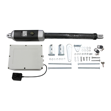
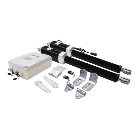
2. For Gate Arm 1, assemble the Post Bracket Assembly and Gate Bracket Assembly, and
temporarily connect them to the gate actuator with the clevis pins. Note: Leave the Post Pivot
Bracket to rotate freely for the moment.
3. Put the gate arm into manual mode by removing the release plug inserting the key and
turning 90o.
4. Move the gate to the fully open position, retract the gate arm fully, then temporarily secure the
brackets to the gate and the post with two C clamps. Note that the mounting position should
be as per Figure 5. Verify that the gate arm is level.
5. Check that there is at least 2.5cm between the gate and the gate arm as per Figure 10. If
clearance is too low, rotate the Post Pivot Bracket and/or move the Post Bracket Assembly.
6. Manually close the gate and verify that it can get to the closed position without reaching the
end of the actuator stroke. If the gate can close past the closed position this is okay, it can be
adjusted back with the limit switches.
7. While the clamps are still securely in place, carefully close and reopen the gate to check that
the gate arm will not bind.
8. Once the position is correct, lock the Post Pivot Bracket with the M8x30mm bolt and nut.
9. Mark the bolt-hole positions on the gate post and the gate itself. Note: Mark the hole in the
centre of each slot, this will allow some slight adjustments.
10. Remove the C clamps, then drill 10.5mm diameter holes in the marked locations.
11. Bolt the Post Bracket Assembly and the Gate Bracket Assembly in place using the bolts,
washers and nuts provided.
12. Reattach the gate arm with the clevis pins, and check that the gate can open and close
smoothly by hand.
13. Once the gate is operating correctly, put the gate arm back into automatic mode by turning
the key and replacing the release plug.
14. For GTR058 Dual Gate Opener, repeat steps 2-12 for Gate Arm 2.
15. Disconnect the power cord for the next section to protect the circuit during installation.
16. Mount the control box to a secure surface at least 100cm above the ground. The gate arm
lead is 3m long, so ensure that it can reach the control box. (Note: For GTR058 the second
gate arm lead is 6m long.)
17. Connect the Gate Arm connector(s) to the outside of the control box.
18. Plug in the power cord to an appropriate weatherproof outlet.
19. Program the Gate Opener using the digital display (refer to page 17 for details).
20. Pair the remote control by pressing the ‘LEARN’ button until the LED turns on, then press the
first button on the remote control twice within 4 seconds. The LED will flash 3 times when
pairing is successful.
21. Operate the gate arm to verify that the motor is correctly installed and stops at the right place.
22. Close the control box, ensuring that all wires are in place.
23. Check operation regularly and ensure maintenance is done as required.
