Richmond GTR207 User manual

GTR207 Installation Manual: Rev 1b 1
Low Voltage Sliding Gate Opener
User Manual GTR207
WARNING
Instructions must be read before beginning installation. Please follow these instructions carefully, incorrect installation could
aect gate operation. If you require more information, please contact your local Richmond Wheel & Castor Co branch.
AU: 1300 474 246 NZ: 0800 61 71 81 International: +613 9551 2233
For installation or troubleshooting assistance visit richmondau.com/gate-motor-support/
When mounting and positioning the motor ensure that the power cable is unplugged. The motor cover will need to be removed to mount
the motor to the mounting plate.
Please Note: This motor runs on 24VAC Power as standard but can also be operated by 24VDC Battery Backup or Solar Power.
Gate in closed position Gate in open position
Viewed from inside the property
For accessories: please refer to the relevant accessory manuals for instructions on wiring them to the GTR207 motor.

GTR207 Installation Manual: Rev 1b 2
Optional Accessories Available:
Additional Remotes (GTR179): Spare/Additional remotes for the automatic gate kit, these will
need to be paired to the motor.
Remote External Receiver (GTR197): Allows more remotes to be paired to the motor. Pair up to
250 remotes with this accessory.
Wireless Keypad (GTR180): Allows secure access through the gate used with a user set code.
Wireless Push Button (GTR201): Allows access through the gate at the push of a button.
Hard Wire Push Button (GTR202): Allows access through the gate at the push of a button.
Reective Photocells (GTR208): Increase safety during opening/closing by preventing gates
from closing on vehicles/pedestrians.
Warning Light (GTR198): Alerts people near the gate and users that the gate is in operation.
Solar Kits Available: Solar panels and more available to get this gate kit running on solar power.
Please contact your nearest authorised dealer for compatible solar panels in your state/region.
Please refer to the relevant manual for each accessory for instructions on wiring
them to the GTR207 low voltage gate motor.

GTR207 Installation Manual: Rev 1b 3
Contents:
Gate Opening Default Setting Information 4
General Safety 5
Parts List 6
Technical Specications 7
Motor Installation
Before you start 8
Tools Required / Example Sliding Gate Setup 9
Step 1 – Gate Preparation 10
Step 2 – Mounting the Low Voltage Power Supply 11
Step 3 – Motor Pad Footing 12
Step 4 - Motor Position Installation 12
Step 5 – Drilling Holes for Anchor Bolts 13
Step 6 – Fitting the Mounting Plate & Motor 13
Step 7 – Gear Rack & Motor Alignment 14
Step 8 – Limit Travel Stops 16
Step 9 – Powering the Motor 18
Step 10 – Testing the Limit Travel Stops 19
Programming and Wiring
Control Board Diagrams 20
Dip Switch Adjustment 23
Further Settings and Programming 24
Battery/Solar Connection 27
Connecting Battery Backup (sold separately) 27
Connecting Solar Power (sold separately) 28
Maintenance 28
Troubleshooting 29
Clearing and Pairing Remotes 30
Additional Drawings and Diagrams 31
For accessories: please refer to the relevant accessory
manuals for instructions on wiring them to the GTR207 motor.

GTR207 Installation Manual: Rev 1b 4
Gate Opening Default Setting Information:
The gate motor will open the gate to the right-hand side as its default setting (refer to g 1).
Default operation:
Motor mounted on the right-hand side
Left-Hand Opening:
Motor mounted on the left-hand side
Fig 01
Fig 02
Before Installing: Test the motor by plugging it into a power source and pressing the remote. You will see the motor cog turn. When it
stops (after approx 1 minute), press the remote again to see it turn in the opposite direction. This will give you an understanding of the
way in which the motor will move the gate.
If your gate needs to open from the other direction (to the left, refer to g 2) your motor needs to be mounted on
the left-hand side as shown below, you will need to switch DIP SWITCH 5 from OFF to ON (refer to page 23)
Press the rst/top button
on the remote.
Note: Ensure that the motor is unplugged before proceeding with installation. Please keep ngers away from the motor cog whilst it is turning.
Any works done to the motor must be completed whilst the power is o and the motor is unplugged
The motor cog will turn counter-clockwise,
moving the gate frame.
The gate will then move in the set
direction. Default: right-hand open.

GTR207 Installation Manual: Rev 1b 5
Thank you for choosing this sliding gate opener. Please read the manual carefully before assembling and using
the opener. Do not leave out the manual if you send this product to a third party. This product complies with the
recognised technical standards and safety regulations. Our company has the right to change this manual without
prior notice.
General Safety:
Warning: Incorrect or improper use of this product can cause damage to persons,
animals or properties.
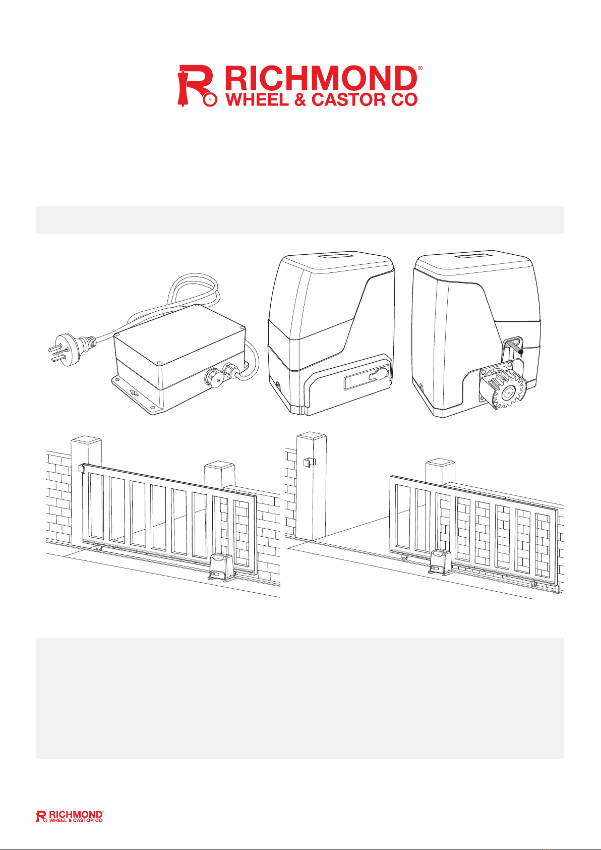
• Please ensure that the input voltage to the low voltage power supply used matches with the supply voltage of
gate opener (AC240V 50Hz).
• To avoid damaging gas, power or other underground utility lines, contact the relevant authority BEFORE
digging.
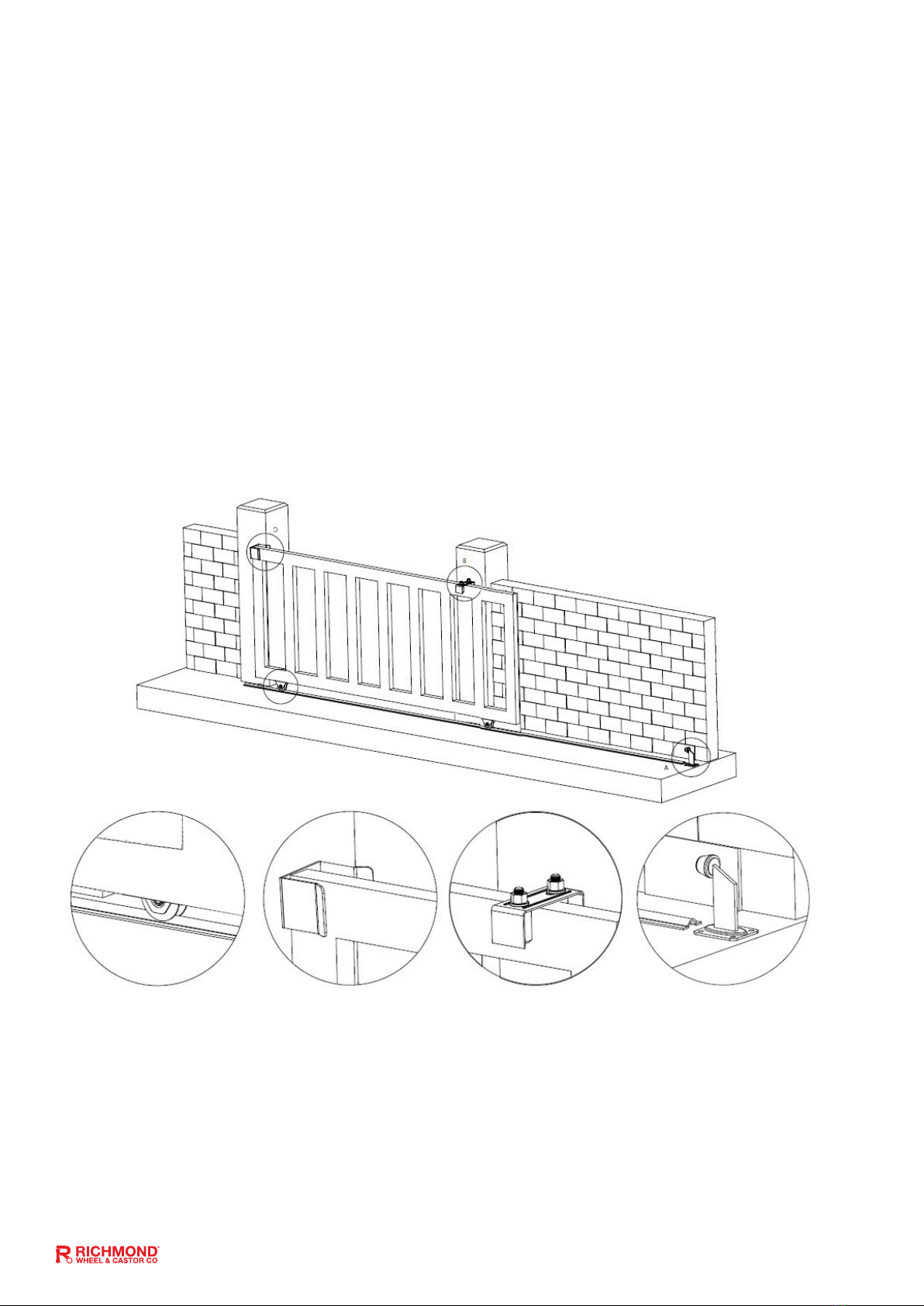
• All potential hazards and exposed pinch points of the gate must be eliminated or guarded prior to installation
of this gate motor.
• Never mount any device that operates the gate motor where the user can reach over, under, around or
through the gate to operate the controls. These must be placed at least 1.8m from any moving part of the
moving gate.
• Ensure power plug is disconnected from the power socket during installation or maintenance.
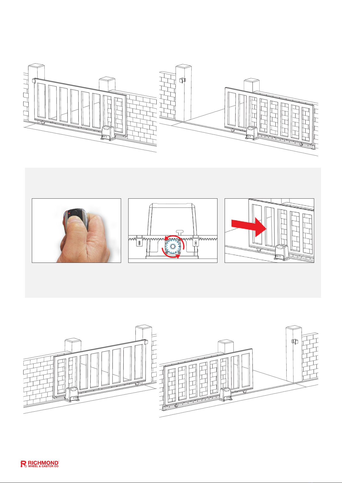
• Keep remote control and other control devices out of children’s reach, in order to avoid unintentional
activation.
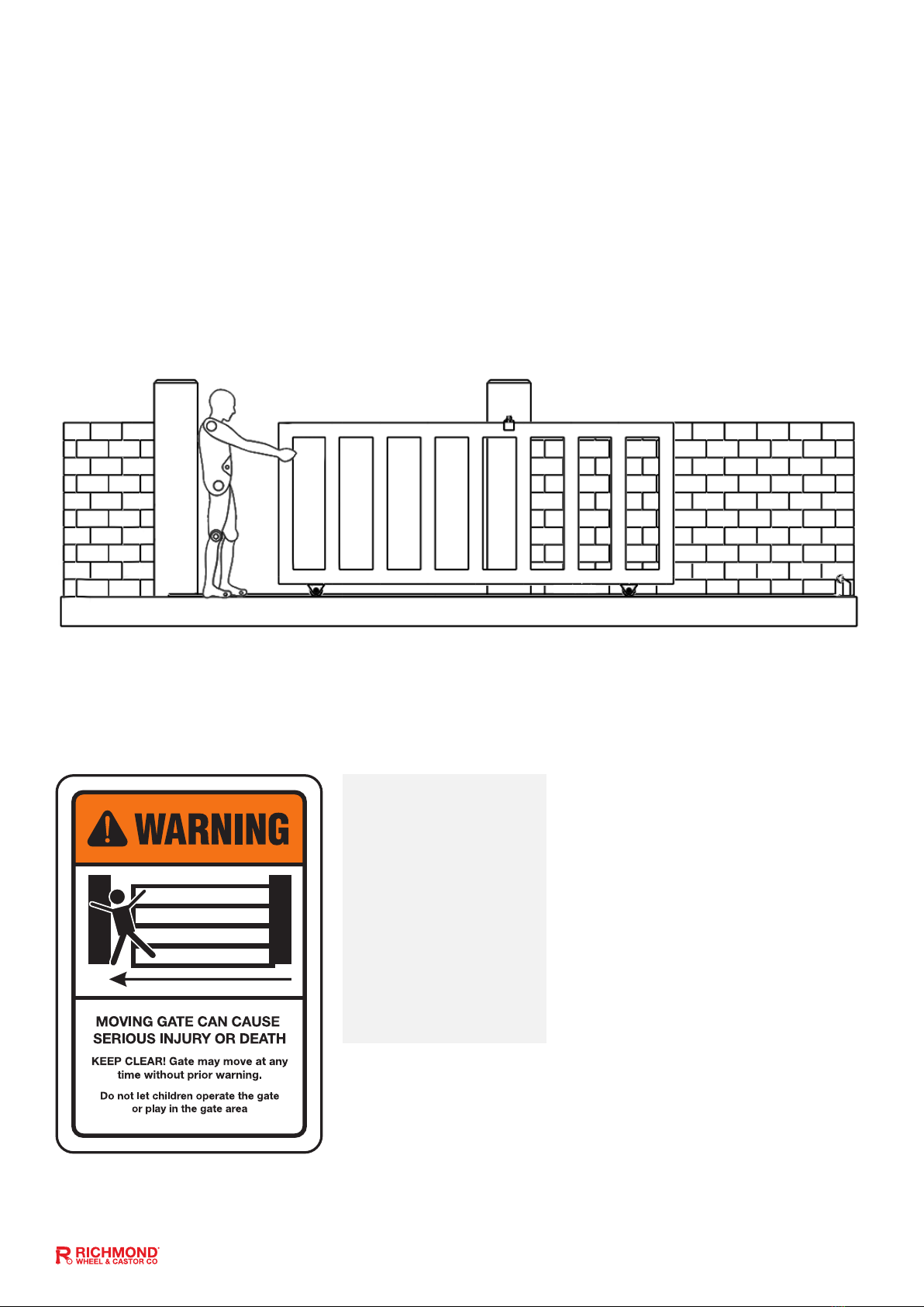
• Never allow anyone to hang onto the gate while moving.
• Please ensure a warning sign provided is tted to the gate.
• If required, install infrared photocells (sold separately) to detect obstructions and prevent injury or damage.
• Instruct all users about the control systems provided and the manual opening operation in case of
emergency.
• Ensure that the power cable is connected to a RCD protected power outlet that has been installed by a
qualied electrician.
• Do not install the product in an explosive atmosphere or where there is any danger of ooding.
• This product was exclusively designed and manufactured for the use specied in the present documentation.
Any other use not specied in this documentation could damage the product and be dangerous.
• Only use original parts for any maintenance or repair operation. Richmond Wheel & Castor Co declines all
responsibility with respect to the automation safety and correct operation when other supplier’s components
are used.
• Do not modify the automation components, unless explicitly authorised by Richmond Wheel & Castor Co.
• The user must avoid any attempt to carry out any works or repairs on the motor, and should always request
the assistance of qualied personnel.
• This motor is suitable for use on one sliding gate only.
• Anything which is not expressly provided for in these instructions is not allowed and will void warranty.
• Dispose of all packing materials (plastic, cardboard, polystyrene etc.) according to current guidelines.
Keep plastic bags and polystyrene out of children’s reach.
Please save these instructions for future use.

GTR207 Installation Manual: Rev 1b 6
Parts List:
No. Picture Name Quantity
1Main motor 1
2Motor Mounting Plate 1
3
24VAC low voltage power supply with
30m cable (Pre-wired into the motor)
Fasteners for mounting the low voltage power supply
are not included. Refer to pg 11 for more info
1
4
Manual release keys
(These keys are needed during power
outage, keep on hand)
2
5Remote controls
(factory paired to motor) 2
6Gate Warning Signage
(must be tted to gate) 1
7In the accessories box you will nd
the items below: 1
7a Limit travel stops
(left hand & right hand) 2
7b Limit switch mounting
plate screws M6X18 4
7c M12 x 100mm masonry anchor bolts
(Drill bit size: M12 masonry) 4
7d Motor mounting set screws M10 x
50mm, spring & at washers 4

GTR207 Installation Manual: Rev 1b 7
Technical Specications:
Model GTR207
Power supply 240V/50Hz
Motor power 170W
Gate moving speed 16-18m/min
Maximum weight of gate 800 Kg
Remote control distance Up to 30m
Remote control mode Single button mode
Limit switch Spring limit switch
Noise Up to 58dB
Working duty S2, 20min (20 minutes continuous operation)
IP Rating IP54
Maximum Remote
Controls to be paired 25
Frequency 433.92 MHz
Working temperature -20°C ~ +70°C
Fig 03

GTR207 Installation Manual: Rev 1b 8
Motor Installation:
Before you start
• The GTR207 Sliding Gate Automatic kit is suitable for powering the opening and closing motion of
gates up to 800kg in weight, and up to a length of 8m on level, at ground.
• Gate motion is achieved by the rotating cog of the gate motor driving the gear rack tted to the moving
gate (sold separately).
• The gate motor requires you to press the remote control once to open, and once again to close. This is
a safety feature to ensure safe operation.
• The gate motor itself must be tted within private property, never externally to a property’s boundary.
• This premium motor has a range of optional accessories which can be added, such as solar power,
battery backup, infrared photocells, keypads, push buttons, and warning light.
The low voltage power supply connects to your power point and reduces the voltage to 24V AC. This lower
and safer voltage can then be ran to your gate motor to power the motor. Power Supply: The GTR207
requires 1 x 10Amp 240V AC 50Hz power supply.
If your power supply and power point are mounted outdoors a RCD Protected Weatherproof PowerPoint
will be required. This will require a licensed electrician to install.
Any works done to the motor must be completed whilst the power is o and the motor is unplugged.
The gate motor will open the gate to the right-hand side as its default setting (refer to g 1).
Low Voltage
Power Supply:
How it Works
Please Note:
• Your power outlet should be no more than 1m from the low voltage power supply.
• If your power outlet is more than 1m from the low voltage power supply, you will require a licensed
electrician to t a new power cable.
• Any excess cable length should be cable tied and secured out of the way of moving objects.
• If the 30m cable supplied with this product is not enough length to reach your gate. A licenced
electrician can extend the length of the cable up to 60m. At this distance, the low voltage power supply
will be sucient to power a sliding gate up to 400kg.
• If your gate is over 60m from a convenient location for a power point consult with your local electrician
to t a larger 24VAC power supply and size the cable so suit your requirements.
Low Voltage
Power Supply
240VAC/50Hz
Plug in the
10AMP power
point
1m Cable
2 Pin Plug
(Supplied on
30m Cable)
Low voltage
Power to the Gate
24VAC
Fig 04

GTR207 Installation Manual: Rev 1b 9
For Installing Your Gate Motor, You Will Need:
• Power drill
• Tape measure
• Level
• 12mm Masonry Drill Bit (for the 4 motor masonry anchor bolts)
• Socket and Spanner Set
• Phillips Head Screwdriver
Example Sliding Gate Setup:
If you require any gate hardware, contact Richmond Wheel & Castor Co or an authorised reseller.
Gate Track and
Track Wheels
Gate Guide
Rollers
Gate End
Catch
Gate
Stopper

GTR207 Installation Manual: Rev 1b 10
Step 1 - Gate Preparation Before Adding
Your Sliding Gate Motor:
• Ensure that the sliding gate is correctly installed.
• The gate is horizontal and level and the gate can glide back and forth smoothly when moved by hand
before installing the Automatic Gate Opener.
• Wheels and guide rollers should rotate easily and be free from dirt/grime.
• Track should be at, level and rmly axed.
• Any misalignment in the gate will aect performance of the automatic gate opener.
The gate should slide smoothly by hand before attempting to install the gate opener.
Please ensure that the motor power cable is not plugged in at any stage before Step 9
Please Note:
The warning signage
provided (Part 6)
must be displayed on
the street facing side
of your automatic
gate at all times.

GTR207 Installation Manual: Rev 1b 11
Step 2 - Mounting the Low Voltage Power Supply
For your convenience the GTR207 gate motor is supplied with 30m of cable, prewired to a low voltage power supply. This
will allow you to mount your low voltage power supply beside a standard domestic 10AMP 240Volt power point (in your
garage or next to an outdoor power point). The low voltage power line can then be ran to your gate entrance to power your
gate opener. The 2 core cable supplied is suitable for direct burial without needing to be run through electrical conduit.
Measure the distance from the power supply to your gate
• Place the motor approximately where you want it to sit near the gate
• Run the 30m cable from the gate motor to your desired mounting postion.
Please ensure that enough cable is left for the motor to be positioned and installed.
Any excess cable length should be cable tied and secured out of the way of moving objects.
There are 2 main methods that can be used for running the cable when installing the power supply:
Option 1: Run the cable across the yard/property and bury it.
Option 2: Run the cable along the fence line of the property and secure out of the way.
For added protection the cable can be run through electrical conduit.
To mount the low voltage power supply
box to a masonry wall (brick/concrete):
• Drill 8mm diameter holes with a masonry drill bit.
• Tap in 8mm diameter wall plugs and secure the
box to the wall using 10 guage screws.
To mount the low voltage power supply
box to a timber surface:
• Pilot drill the marked holes.
• Secure the box with 10 guage timber screws.
Mount The Low Voltage Power Supply
• Place the low voltage power supply in the
desired mounting position
• Using a marker, mark the (4) positions for
your anchor bolts ready for drilling
(refer to g 08)
Fig 05 Fig 06
Fig 07
Fig 08
Please Note: Your power outlet should be no more than 1m from the low voltage power supply.
Please Note: fasteners for mounting the low voltage power supply are not included in this kit
Low Voltage
Power Supply
Gate
Motor
30m
Cable
Option 01
Low Voltage
Power Supply
Gate
Motor
30m
Cable
Option 02
Fig 09
185mm
200mm
6.5mm
Mounting
Hole
80mm Thickness
170mm
95mm
120mm

GTR207 Installation Manual: Rev 1b 12
Step 3 - Motor Pad Footing (Minimum Requirement):
• The motor pad concrete footing requires an area of no less than 450mm long x 300mm wide and a
minimum depth of 200mm (Standard requirement).
• Ensure surface is level and parallel to the driveway
Step 4 - Motor Position Installation:
• Insert the key and open the manual release bar to put the motor into manual mode, and check
that the motor cog rotates freely by hand (As per Fig 23).
• Place the motor and motor mounting plate on the concrete pad.
• Make sure the distance between the gate motor cog and gear rack position are aligned.
• Mark all four corners of the mounting plate on the concrete pad using a pencil, chalk or similar,
to ensure the mounting plate is in the correct position before drilling.
• Remove motor from the mounting plate.
Mounting Plate Dimensions:
Fig 10
Fig 11 Fig 12
21-17mm
53-57mm
Sliding Gate Frame (in open position)
Mark
corners
of the
mounting
plate with
a pencil,
chalk, or
similar.

GTR207 Installation Manual: Rev 1b 13
Step 5 - Drilling Holes for Anchor Bolts:
• Mark the (4) positions for your anchor bolts ready for drilling (refer to Fig 13).
• Remove Mounting plate.
• Using a M12 masonry drill bit, drill holes to a minimum depth of 120mm (Fig 14).
Fig 13
Fig 15
Fig 17
Fig 14
Fig 16
Fig 18 Fig 19 Fig 20
Step 6 - Fitting Mounting Plate & Motor:
• Fit motor mounting plate back into place and t and tighten anchor bolts (as per gures 15 and 16).
• Fit motor back on mounting plate, ensuring the power cord is positioned into the end slot of the mounting
plate in the direction of the power point, making sure there are no pinch points (as per g 17).
• Slide rubber grommet along the power lead and into the end slot of the mounting plate (as per gures 18 & 19).
• Bolt motor to the mounting plate using the M10 x 50mm bolts with spring and at washers provided and
tighten as required (as per gure 20).
208mm
135mm
Tighten bolts using
spanner or socket set
Insert the M10 x 50mm bolts
(Part 7d), spring washers,
and at washers provided
through motor housing and
screw into welded nut on the
baseplate.
Hand-tighten set screws
before nal adjustment of motor.

GTR207 Installation Manual: Rev 1b 14
Step 7 - Gear Rack & Motor Alignment:
• Insert the key and open the manual release bar to put the motor into manual mode, and check that the
motor cog rotates freely by hand (as per g 23).
• Ensure that the gate drive cog has a minimum clearance of 1-2mm along the entire length of gear rack
tted to the gate (as per Fig 21)
• Ensure cog and rack are correctly aligned. Under no circumstances should the gate motor drive cog
carry any weight of the gate. It is the task of the gate castors or wheels to carry the weight of the gate.
(As per Fig 22)
• If the gate doesn’t slide freely by hand, adjust gear racks height accordingly until the full length of gate
slides freely by hand
To put the gate motor into manual mode, insert the
key and open the manual release bar as shown
At this stage of nal assembly, the cover is removed (not shown) and the power cable is still unplugged.
In manual mode, the gear can turn freely
and the gate can be operated by hand
Gear rack correctly aligned at 90°
to the motor cog
Gear rack misaligned.
Do not attempt to use if misaligned.
Fig 23
Fig 21
Fig 22

GTR207 Installation Manual: Rev 1b 15
Fig 24
At this stage of nal assembly, the cover is removed (not shown) and the power cable is still unplugged.

GTR207 Installation Manual: Rev 1b 16
Step 8 - Limit Travel Stops:
Included in your gate motor kit are two limit travel
stops (Part 7a) which must be tted to the gear
racks on your gate to ensure safe operation.
The limit travel stops are designed to set the
desired opening and closing position of your
gate. These limit travel stops are designed to
come into contact with the spring limit switch.
Please note: gates can open and close in
dierent positions due to dierent weights of
gates, terrains, slopes (uphill or downhill). The
distance the gate will travel after contacting
the spring limit switch may vary.
Test the spring limit travel stops by moving the gate manually until you hear a click, making sure contact is
made with the spring limit switch on the motor.
To Reset: When setting new limit travel stop positions please ensure that you turn the power o and then on
again. Turning the power o will reset the limit travel stop memory, allowing for new limit travel stop positions
to be recognised by the motor.
Setting the Limit Travel Stops:
Closed Position:
• Position gate 150-200mm back from
the gate end catch closed position.
This will help in making sure you do
not slam the gate into the end stop/
catch when setting the closed position
under power.
• Fit limit travel stop onto the top of gear
rack at the point where it meets the
spring limit switch on the motor.
• Tighten locking screws.
Open Position:
• Position gate 150-200mm back from
the gate stopper open position. This
will help in making sure you do not
slam the gate into the end stop/catch
when setting the open position under
power.
• Fit limit travel stop onto the top of gear
rack at the point where it meets the
spring limit switch on the motor.
• Tighten locking screws.
Fig 25
Fig 27
Fig 26

GTR207 Installation Manual: Rev 1b 17
Fig 28
Fig 29
M6 x
10mm
M6 x
10mm
GTR207
Motor
Gear
Rack
Limit
Travel
Stop
Motor
Gear
Cog
Spring
Limit
Switch
Mounting
Plate
This diagram
shows the gate
in the open
position

GTR207 Installation Manual: Rev 1b 18
Step 9 - Powering the Motor:
• Ensure that the outer cover has been tted and fastened back onto the motor housing.
• Before powering up the motor make sure the gate can travel by hand in manual mode (key unlocked).
• Slide the gate to between the middle of the posts, approximately (see below diagrams).
• Lock the key (key locked) in readiness for automatic mode.
• Plug the power cord from the low voltage power supply into the power outlet.
• Remote controls (Part 5) included in this kit are factory paired ready for use.
Please Note:
• The default setting is opening to the right.
• Press the remote control and the gate will open until the spring limit travel stop hits the spring limit
switch. Press the remote control again and the gate will close.
• Soft start/soft stop function - The GTR207 is set by default to provide the soft start/soft stop function.
We recommend this default position is always maintained.
Your motor is now set up for basic remote control operation. To set further
functions and settings, see pages 21-28
For accessories: please refer to the relevant accessory
manuals for instructions on wiring them to the GTR207 motor.

GTR207 Installation Manual: Rev 1b 19
Step 10 - Testing the Limit Travel Stops:
Testing the closed position
• Ensure motor is plugged in as per step 9 and the gate is in the open position.
• Press remote (remotes included in kit are factory paired to the motor). The gate will begin to close.
• The limit travel stop will hit the spring limit switch and the gate will stop.
• When the gate stops, measure the distance remaining between the gate and the desired closed position.
• You have now determined the closed position of the gate when the travel limit stop hits the spring limit
switch.
• Adjust the limit travel stop from the measurement you have taken to get your nal gate closed position.
The ideal closed nal position for the gate frame is 10-15mm from closed gate end catch (GTR019).
Testing the open position
• Press remote. The gate will begin to open.
• The limit travel stop will hit the spring limit switch and the gate will stop.
• When the gate stops, measure the distance remaining between the gate and the desired open position.
• You have now determined the open position of the gate when the travel limit stop hits the spring limit
switch.
• Adjust the limit travel stops from the measurement you have taken to get your nal gate open position.
The ideal open nal position for the gate frame is 10-15mm from the gate stopper (GTR017).
To Reset: When setting new limit travel stop positions please ensure that you turn the power o and then on
again. Turning the power o will reset the limit travel stop memory, allowing for new limit travel stop positions
to be recognised by the motor.
Fig 30

GTR207 Installation Manual: Rev 1b 20
Programming and Wiring: Control Board Wiring Diagram 01
Ensure power is o before any modications are made
Dip Switches
J10 Terminal
J8 Terminal
J4 Terminal
J2 Terminal
24VDC BAT
Terminal
J7 Terminal
Fuse holder
J1 Terminal
Learn Button Potentiometers
Fig 31
+
_
Please refer to page 25 and 26 for added description of the terminals
Other manuals for GTR207
1
Table of contents
Other Richmond Gate Opener manuals

Richmond
Richmond GTR058 User manual

Richmond
Richmond GTR502 User manual

Richmond
Richmond GTR099 User manual

Richmond
Richmond GTR064 User manual

Richmond
Richmond GTR211 User manual

Richmond
Richmond GTR058 User manual

Richmond
Richmond GTR181 User manual

Richmond
Richmond GTR156 User manual

Richmond
Richmond GTR058 User manual

Richmond
Richmond GTR500 User manual