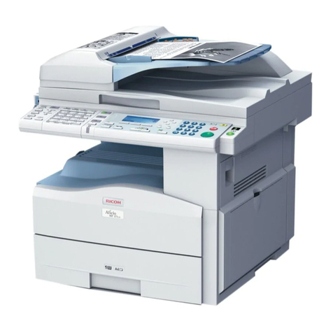
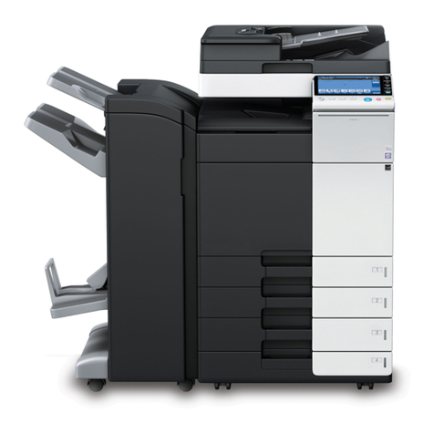
Ricoh M281 Series User manual

D255/D256/M281/M282
SERVICE MANUAL

It is the reader's responsibility when discussing the information contained
within this document to maintain a level of confidentiality that is in the best
interest of Ricoh USA, Inc. and its member companies.
NO PART OF THIS DOCUMENT MAY BE REPRODUCED IN ANY
FASHION AND DISTRIBUTED WITHOUT THE PRIOR
PERMISSION OF RICOH USA, Inc.
All product names, domain names or product illustrations, including
desktop images, used in this document are trademarks, registered
trademarks or the property of their respective companies.
They are used throughout this book in an informational or editorial fashion
only and for the benefit of such companies. No such use, or the use of
any trade name, or web site is intended to convey endorsement or other
affiliation with Ricoh products.
2016 RICOH USA, Inc. All rights reserved.

The Service Manual contains information
regarding service techniques, procedures,
processes and spare parts of office equipment
distributed by Ricoh USA, Inc. Users of this
manual should be either service trained or
certified by successfully completing a Ricoh
Technical Training Program.
Untrained and uncertified users utilizing
information contained in this service manual to
repair or modify Ricoh equipment risk personal
injury, damage to property or loss of warranty
protection.
Ricoh USA, Inc.
WARNING

LEGEND
PRODUCT
CODE COMPANY
LANIER RICOH SAVIN
D255 MP 501SPF MP 501SPF MP 501SPF
D255-17 MP 501SPF TL MP 501SPF TL MP 501SPF TL
D256 MP 601SPF MP 601SPF MP 601SPF
M281 SP 5300DN SP 5300DN SP 5300DN
M281-17 SP 5300DN TL MP 501SPF TL MP 501SPF TL
M282 SP 5310DN SP 5310DN SP 5310DN
DOCUMENTATION HISTORY
REV. NO. DATE COMMENTS
* 07/2016 Original Printing
Rev 03/08/2017

SM i D255/D256/M281/M282
D255/D256/M281/M282
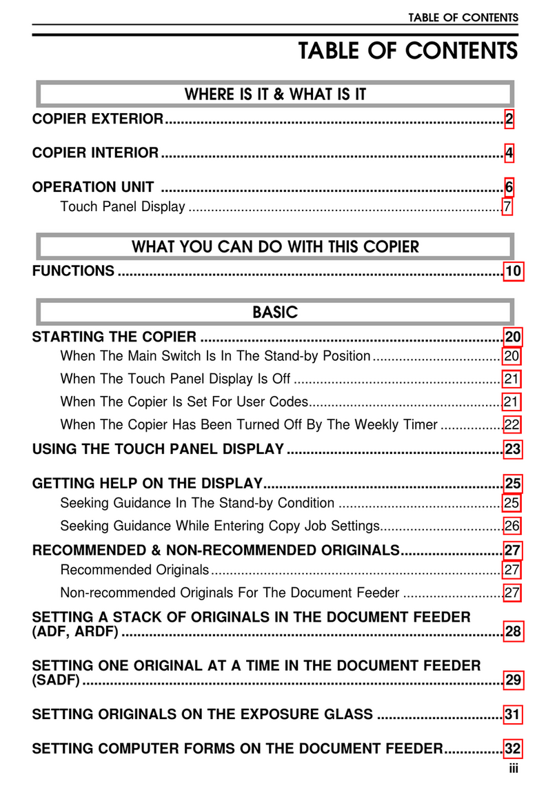
TABLE OF CONTENTS
1. PRODUCT INFORMATION...........................................................1-1
1.1 MACHINE CODES AND PERIPHERALS CONFIGURATION ......................................1-1
1.1.1 MAIN MACHINE..................................................................................................1-1
1.1.2 OPTIONS ............................................................................................................1-2
2. INSTALLATION .............................................................................2-1
2.1 INSTALLATION REQUIREMENTS................................................................................2-1
2.1.1 ENVIRONMENT..................................................................................................2-1
2.1.2 MACHINE LEVEL................................................................................................2-2
2.1.3 MINIMUM SPACE REQUIREMENTS.................................................................2-2
2.1.4 MACHINE DIMENSIONS....................................................................................2-3
2.1.5 POWER REQUIREMENTS.................................................................................2-4
2.2 MAIN MACHINE INSTALLATION ..................................................................................2-5
2.2.1 INSTALLATION FLOWCHART ...........................................................................2-5
2.2.2 ACCESSORY CHECK ........................................................................................2-5
MP 501/601 .............................................................................................................2-5
SP 5300/5310..........................................................................................................2-7
2.2.3 INSTALLATION PROCEDURE...........................................................................2-8
2.2.4 SMC STORAGE..................................................................................................2-8
2.2.5 IMPORTANT NOTICE ON SECURITY ISSUES (MP 501/601 ONLY)...............2-9
2.2.6 SETTINGS ACCORDING TO THE SERVICE CONTRACT.............................2-14
Meter Click Charge................................................................................................2-14
2.2.7 MOVING THE MACHINE..................................................................................2-15
2.2.8 TRANSPORTING THE MACHINE....................................................................2-16
2.3 CASTER TABLE TYPE M24 (D3C7-01)......................................................................2-19
2.3.1 ACCESSORY CHECK ......................................................................................2-19
2.3.2 INSTALLATION PROCEDURE.........................................................................2-21
When installing with the paper feed unit ...............................................................2-21
2.4 PAPER FEED UNIT PB1100 (D3C2-01, 02) ...............................................................2-22
2.4.1 ACCESSORY CHECK ......................................................................................2-22
2.4.2 INSTALLATION PROCEDURE.........................................................................2-23
When installing with the caster table.....................................................................2-23
Installing the optional paper feed unit on the caster table ....................................2-23
When installing two or more optional paper feed units.........................................2-29
Installing the main machine on the optional paper feed unit.................................2-32

D255/D256/M281/M282 ii SM
2.5 OPTIONAL COUNTER INTERFACE UNIT TYPE M12 (B870-21) (MP 501/601 ONLY)
2-38
2.5.1 ACCESSORY CHECK ......................................................................................2-38
2.5.2 INSTALLATION PROCEDURE.........................................................................2-38
2.6 NFC CARD READER TYPE M24 (D3CP-08) (MP 501/601 ONLY)............................2-45
2.6.1 ACCESSORY CHECK ......................................................................................2-45
2.6.2 INSTALLATION PROCEDURE.........................................................................2-46
2.7 ENHANCED SECURITYHDD OPTION TYPE M10 (D792-09)..................................2-60
2.7.1 ACCESSORY CHECK ......................................................................................2-60
2.7.2 INSTALLATION PROCEDURE (MP 501/601)..................................................2-62
After Installing the HDD.........................................................................................2-79
2.7.3 INSTALLATION PROCEDURE (SP 5300/5310)...............................................2-80
After Installing the HDD.........................................................................................2-92
2.8 HARD DISK DRIVE OPTION TYPE P8 (M500-05) (SP 5300/5310 ONLY)................2-93
2.8.1 ACCESSORY CHECK ......................................................................................2-93
2.8.2 INSTALLATION PROCEDURE.........................................................................2-94
After Installing the HDD.......................................................................................2-106
2.9 INTERNAL OPTIONS ................................................................................................2-107
2.9.1 LIST OF SLOTS..............................................................................................2-107
2.10 IEEE 1284 INTERFACE BOARD TYPE M19 (D3C0-17) ...................................2-108
2.10.1ACCESSORY CHECK ....................................................................................2-108
2.10.2INSTALLATION PROCEDURE.......................................................................2-108
2.11IEEE 802.11 INTERFACE UNIT TYPE M24 (M500-08)............................................2-109
2.11.1 ACCESSORY CHECK ....................................................................................2-109
2.11.2 INSTALLATION PROCEDURE.......................................................................2-109
2.12 BLUETOOTH INTERFACE UNIT TYPE D (D566-01) (MP 501/601 ONLY).......2-110
2.12.1ACCESSORY CHECK ....................................................................................2-110
2.12.2INSTALLATION PROCEDURE.......................................................................2-110
2.13 USB DEVICE SERVER OPTION TYPE M19 (D3BC-28, 29)............................. 2-111
2.13.1ACCESSORY CHECK .................................................................................... 2-111
Interface Board....................................................................................................2-111
2.13.2INSTALLATION PROCEDURE.......................................................................2-112
What Do the LED Indicators Mean?....................................................................2-115
Notes for Energy Save Mode Setting..................................................................2-115
IP Address Setting...............................................................................................2-116
Check All Connections ........................................................................................2-117
2.14 FILE FORMAT CONVERTER TYPE M19 (D3BR-04) (MP 501/601 ONLY).......2-118
2.14.1ACCESSORY CHECK ....................................................................................2-118
2.14.2INSTALLATION PROCEDURE.......................................................................2-118

SM iii D255/D256/M281/M282
2.15 EXTENDED USB BOARD TYPE M19 (D3BS-01)..............................................2-119
2.15.1ACCESSORY CHECK ....................................................................................2-119
2.15.2INSTALLATION PROCEDURE.......................................................................2-119
2.16 SD CARD OPTIONS...........................................................................................2-120
2.16.1SD CARD SLOTS............................................................................................2-120
2.17 SD CARD APPLI MOVE......................................................................................2-121
2.17.1OVERVIEW .....................................................................................................2-121
2.17.2SD CARD APPLI MOVE..................................................................................2-121
2.17.3MOVE EXEC...................................................................................................2-122
2.17.4UNDO EXEC...................................................................................................2-122
2.18 OCR UNITTYPE M13 (D3AC-23, 24, 25) (MP 501/601 ONLY) ........................2-124
2.18.1ACCESSORY CHECK ....................................................................................2-124
2.18.2INSTALLATION PROCEDURE.......................................................................2-124
2.18.3RECOVERY PROCEDURE............................................................................2-128
2.19 XPS DIRECT PRINT OPTION TYPE M24 (D3CP-12).......................................2-129
2.19.1ACCESSORY CHECK ....................................................................................2-129
2.19.2INSTALLATION PROCEDURE.......................................................................2-129
2.20 IPDS UNIT TYPE M24 (M500-02, 03, 04) ..........................................................2-130
2.20.1ACCESSORY CHECK ....................................................................................2-130
2.20.2INSTALLATION PROCEDURE.......................................................................2-130
2.21 VM CARD TYPE P8 (M500-09, 10, 11) (SP 5300/5310 ONLY) .........................2-131
2.21.1ACCESSORY CHECK ....................................................................................2-131
2.21.2INSTALLATION PROCEDURE.......................................................................2-131
2.22 DATAOVERWRITESECURITY UNIT TYPE M19 (D3BS-03) (MP 501/601 ONLY)
2-132
2.22.1OVERVIEW .....................................................................................................2-132
2.22.2ACCESSORY CHECK ....................................................................................2-132
2.22.3BEFORE YOU BEGIN THE PROCEDURE....................................................2-133
Seal Check and Removal....................................................................................2-134
2.22.4INSTALLATION PROCEDURE.......................................................................2-135
2.22.5CONFIGURING "AUTO ERASE MEMORY" (PERFORMED BYTHE CUSTOMER)
2-138
2.23 SECURITY SETTING..........................................................................................2-140
2.23.1SECURITY FUNCTION INSTALLATION ........................................................2-140
2.23.2DATA OVERWRITE SECURITY (MP 501/601) ..............................................2-141
Before You Begin the Procedure.........................................................................2-141
Using Auto Erase Memory...................................................................................2-142
2.23.3DATA OVERWRITE SECURITY (SP 5300/5310)...........................................2-143
Before You Begin the Procedure.........................................................................2-143

D255/D256/M281/M282 iv SM
Using Auto Erase Memory...................................................................................2-144
Checking the Auto Erase Memory Status ...........................................................2-144
2.23.4HDD ENCRYPTION (MP 501/601).................................................................2-145
Before You Begin the Procedure:........................................................................2-145
Enable Encryption Setting...................................................................................2-146
Backing Up the Encryption Key...........................................................................2-148
Encryption Key Restoration.................................................................................2-149
2.23.5HDD ENCRYPTION (SP 5300/5310)..............................................................2-150
Before You Begin the Procedure:........................................................................2-150
Enable Encryption Setting...................................................................................2-151
Backing Up the Encryption Key...........................................................................2-152
Encryption Key Restoration.................................................................................2-152
2.24 @REMOTE SETTINGS ......................................................................................2-155
2.25 OPERATION GUIDANCE FOR USERS.............................................................2-160
3. PREVENTIVE MAINTENANCE.....................................................3-1
3.1 YIELD PARTS SETTINGS.............................................................................................3-1
3.1.1 YIELD PARTS REPLACEMENT PROCEDURE.................................................3-1
After installing the new yield parts...........................................................................3-1
Operation check ......................................................................................................3-2
4. REPLACEMENT AND ADJUSTMENT .........................................4-1
4.1 NOTES ON THE MAIN POWER SWITCH....................................................................4-1
4.1.1 PUSH SWITCH...................................................................................................4-1
Characteristics of the Push Switch (DC Switch).....................................................4-1
Shutdown Method....................................................................................................4-2
Forced Shutdown ....................................................................................................4-2
4.2 BEFOREHAND..............................................................................................................4-3
4.3 SPECIAL TOOLS...........................................................................................................4-4
4.4 IMAGE ADJUSTMENT ..................................................................................................4-5
4.4.1 PRINTING ...........................................................................................................4-5
Registration: Leading Edge/Side-to-Side................................................................4-5
Blank Margin............................................................................................................4-6
Main Scan Magnification.........................................................................................4-7
4.4.2 SCANNING (MP 501/601 ONLY)........................................................................4-8
Registration: Platen Mode.......................................................................................4-8
4.4.3 ARDF IMAGE ADJUSTMENT (MP 501/601 ONLY) ...........................................4-9
Registration .............................................................................................................4-9
4.5 FACTORY SP SETTINGS ...........................................................................................4-10
4.5.1 MP 501/601 .......................................................................................................4-10

SM v D255/D256/M281/M282
4.5.2 SP 5300/5310....................................................................................................4-12
4.6 EXTERIOR COVERS (MP 501/601) ...........................................................................4-14
4.6.1 SCANNER FRONT COVER..............................................................................4-14
4.6.2 FRONT COVER ................................................................................................4-15
4.6.3 RIGHT UPPER COVER....................................................................................4-20
4.6.4 RIGHT LOWER COVER...................................................................................4-22
4.6.5 LEFT UPPER COVER ......................................................................................4-26
4.6.6 LEFT MIDDLE COVER .....................................................................................4-27
4.6.7 LEFT LOWER COVER......................................................................................4-29
4.6.8LEFT REAR COVER.........................................................................................4-30
4.6.9 REAR UPPER COVER.....................................................................................4-31
4.6.10REAR MIDDLE COVER....................................................................................4-33
4.6.11 REAR LOWER COVER ....................................................................................4-35
4.6.12REAR CENTER STAY.......................................................................................4-36
4.6.13REAR LEFT STAY.............................................................................................4-37
4.6.14PAPER EXIT COVER........................................................................................4-38
4.6.15PAPER EXIT TRAY ...........................................................................................4-39
4.6.16CONTROLLER COVER....................................................................................4-45
4.7 EXTERIOR COVERS (SP 5300/5310)........................................................................4-47
4.7.1 UPPER COVER ................................................................................................4-47
4.7.2 FRONT COVER ................................................................................................4-50
4.7.3 RIGHT COVER..................................................................................................4-54
4.7.4 LEFT UPPER COVER ......................................................................................4-58
4.7.5 LEFT LOWER COVER......................................................................................4-60
4.7.6 LEFT REAR COVER.........................................................................................4-61
4.7.7 REAR UPPER COVER.....................................................................................4-62
4.7.8 REAR MIDDLE COVER....................................................................................4-64
4.7.9 REAR LOWER COVER ....................................................................................4-66
4.7.10CONTROLLER COVER....................................................................................4-67
4.8 OPERATION PANEL (MP 501/601).............................................................................4-68
4.8.1 OPERATION PANEL.........................................................................................4-68
Before Installing the New Operation Panel...........................................................4-73
4.8.2 INTERNAL PARTS............................................................................................4-73
4.9 OPERATION PANEL (SP 5300/5310) .........................................................................4-74
4.9.1 OPERATION PANEL.........................................................................................4-74
4.9.2 OPU BOARD.....................................................................................................4-75
4.10 SCANNER UNIT (MP 501/601 ONLY)..................................................................4-76
4.10.1SCANNER UNIT................................................................................................4-76
4.10.2SCANNER CARRIAGE.....................................................................................4-78

D255/D256/M281/M282 vi SM
4.11LASER UNIT (MP 501/601).........................................................................................4-82
4.11.1 CAUTION DECAL LOCATION..........................................................................4-82
4.11.2 LASER UNIT .....................................................................................................4-82
4.12 LASER UNIT (SP 5300/5310)...............................................................................4-85
4.12.1CAUTION DECAL LOCATION..........................................................................4-85
4.12.2LASER UNIT .....................................................................................................4-85
4.13 DEVELOPMENT UNIT..........................................................................................4-88
4.13.1DEVELOPMENT UNIT......................................................................................4-88
4.14 DRUM UNIT..........................................................................................................4-91
4.14.1DRUM UNIT......................................................................................................4-91
4.14.2CHARGE ROLLER............................................................................................4-93
4.15 TRANSFER UNIT..................................................................................................4-95
4.15.1TRANSFER ROLLER........................................................................................4-95
4.15.2DISCHARGE PLATE UNIT ...............................................................................4-97
4.16 FUSING UNIT........................................................................................................4-98
4.16.1FUSING UNIT....................................................................................................4-98
4.17 PAPER EXIT UNIT (MP 501/601) .......................................................................4-103
4.17.1PAPER EXIT UNIT..........................................................................................4-103
4.18 PAPER EXIT UNIT (SP 5300/5310)....................................................................4-107
4.18.1PAPER EXIT UNIT..........................................................................................4-107
4.19 PAPER FEED UNIT.............................................................................................4-111
4.19.1PAPER FEED ROLLER, PICKUP ROLLER ................................................... 4-111
4.19.2SEPARATION ROLLER ..................................................................................4-112
4.20 BYPASS TRAY UNIT...........................................................................................4-114
4.20.1BYPASS PAPER FEED ROLLER...................................................................4-114
4.21 DUPLEX UNIT.....................................................................................................4-116
4.21.1DUPLEX UNIT.................................................................................................4-116
4.22 DRIVE UNIT........................................................................................................4-123
4.22.1PAPER FEED MOTOR....................................................................................4-123
4.22.2MAIN DRIVE UNIT..........................................................................................4-125
Main Motor...........................................................................................................4-126
Drum Motor..........................................................................................................4-127
4.23 ELECTRICAL COMPONENTS ...........................................................................4-128
4.23.1CONTROLLER BOX.......................................................................................4-128
Controller Box (MP 501/601)...............................................................................4-128
Controller Box (SP 5300/5310) ...........................................................................4-132
4.23.2CONTROLLER BOARD..................................................................................4-135
Controller Board (MP 501/601) ...........................................................................4-135
Controller Board (SP 5300/5310)........................................................................4-138

SM vii D255/D256/M281/M282
NVRAM on the controller board..........................................................................4-141
4.23.3BICU................................................................................................................4-144
Replacing the NVRAM (EEPROM) on the BiCU.................................................4-145
4.23.4IOB...................................................................................................................4-147
IOB (MP 501/601)................................................................................................4-147
IOB (SP 5300/5310)............................................................................................4-148
Replacing the NVRAM (EEPROM) on the IOB...................................................4-149
4.23.5CONNECT-LEFT PCB ....................................................................................4-150
4.23.6FUSING THERMISTOR CONNECTION PCB................................................4-152
4.23.7POWER PACK ................................................................................................4-153
4.23.8PSU .................................................................................................................4-154
4.23.9HDD (MP 501/601 ONLY) ...............................................................................4-156
Adjustment after Replacement............................................................................4-157
4.24 FANS ...................................................................................................................4-158
4.24.1PSU FAN.........................................................................................................4-158
4.24.2DIRECTION OF INSTALLING THE FANS......................................................4-159
4.25 ARDF (MP 501/601 ONLY) .................................................................................4-160
4.25.1ARDF UNIT .....................................................................................................4-160
4.25.2ARDF PAPER FEED ROLLER, ARDF PICKUP ROLLER..............................4-162
4.25.3ARDF FRICTION PAD ....................................................................................4-163
4.25.4ARDF INVERTER MOTOR.............................................................................4-163
4.25.5ARDF PAPER FEED MOTOR, ARDF PAPER TRANSPORT MOTOR..........4-165
4.26 PAPER FEED UNIT (PAPER FEED UNIT PB1100)...........................................4-168
4.26.1PAPER FEED ROLLER, PICKUP ROLLER ...................................................4-168
4.26.2SEPARATION ROLLER ..................................................................................4-169
4.26.3MAIN BOARD..................................................................................................4-171
4.26.4DRIVE UNIT....................................................................................................4-172
5. SYSTEM MAINTENANCE.............................................................5-1
5.1 FIRMWARE UPDATE....................................................................................................5-1
5.1.1 OVERVIEW .........................................................................................................5-1
5.1.2 FIRMWARE TYPE...............................................................................................5-1
MP 501/601 .............................................................................................................5-1
SP 5300/5310..........................................................................................................5-3
5.1.3 PROCEDURE......................................................................................................5-4
Update procedure (MP 501/601).............................................................................5-5
Update procedure (SP 5300/5310) .........................................................................5-8
5.1.4 ERROR SCREENS DURING UPDATING..........................................................5-9
5.2 RFU UPDATING THE FIRMWARE..............................................................................5-16
5.2.1 RFU PERFORMABLE CONDITION .................................................................5-16

D255/D256/M281/M282 viii SM
5.3 PACKAGE FIRMWARE UPDATE (MP 501/601 ONLY) ..............................................5-17
5.3.1 OVERVIEW .......................................................................................................5-17
5.3.2 IMMEDIATE UPDATE .......................................................................................5-18
5.3.3 UPDATE AT THE NEXT VISIT (RESERVE) .....................................................5-20
How to Set the Machine to Download Firmware Later (RESERVE).....................5-21
How to Check if the Firmware Downloaded with RESERVE................................5-23
How to Install Firmware Downloaded with RESERVE..........................................5-24
5.3.4 UPDATE VIA SD CARD....................................................................................5-27
5.4 UPDATING JAVAVM ....................................................................................................5-29
5.4.1 MP 501/601 .......................................................................................................5-29
Creating an SD Card for Updating........................................................................5-29
Updating Procedure ..............................................................................................5-29
List of Error Messages ..........................................................................................5-30
5.4.2 SP 5300/5310....................................................................................................5-32
Deactivating SDK Applications..............................................................................5-32
Updating JavaVM..................................................................................................5-33
Activating SDK Applications..................................................................................5-34
5.5 CAPTURING THE DEBUG LOGS...............................................................................5-35
5.5.1 OVERVIEW .......................................................................................................5-35
Security of the Operation Log ...............................................................................5-37
5.5.2 RETRIEVING THE DEBUG LOGS ...................................................................5-37
Procedure for Retrieving the Debug Log ..............................................................5-37
5.6 NVRAM DATA UPLOAD/DOWNLOAD........................................................................5-40
5.6.1 UPLOADING CONTENT OF NVRAM TO AN SD CARD.................................5-40
5.6.2 DOWNLOADINGAN SD CARD TO NVRAM....................................................5-41
5.7 UP/SP DATA IMPORT/EXPORT..................................................................................5-43
5.7.1 OVERVIEW .......................................................................................................5-43
Import/export conditions........................................................................................5-43
5.7.2 UP DATA IMPORT/EXPORT (MP 501/601)......................................................5-43
Data that can be imported and exported...............................................................5-43
Data that cannot be imported or exported ............................................................5-43
Exporting Device Information................................................................................5-44
Importing Device Information................................................................................5-45
5.7.3 UP DATA IMPORT/EXPORT (SP 5300/5310) ..................................................5-46
Data that can be imported and exported...............................................................5-46
Data that cannot be imported or exported ............................................................5-46
Exporting Device Information................................................................................5-46
Importing Device Information................................................................................5-47
5.7.4 SP DATA IMPORT/EXPORT (MP 501/601)......................................................5-48

SM ix D255/D256/M281/M282
Data that can be imported and exported...............................................................5-48
Exporting Device Information................................................................................5-48
Importing Device Information................................................................................5-50
5.7.5 SP DATA IMPORT/EXPORT (SP 5300/5310)...................................................5-51
Data that can be imported and exported...............................................................5-51
Exporting Device Information................................................................................5-51
Importing Device Information................................................................................5-52
5.7.6 POSSIBLE SOLUTIONS FOR IMPORT/EXPORT PROBLEMS......................5-53
5.8 ADDRESS BOOK UPLOAD/DOWNLOAD..................................................................5-55
5.8.1 INFORMATION LIST.........................................................................................5-55
5.8.2 DOWNLOAD.....................................................................................................5-56
5.8.3 UPLOAD............................................................................................................5-57
5.9 SMC LIST CARD SAVE FUNCTION...........................................................................5-58
5.9.1 OVERVIEW .......................................................................................................5-58
SMC List Card Save..............................................................................................5-58
5.9.2 PROCEDURE....................................................................................................5-58
MP 501/601 ...........................................................................................................5-58
SP 5300/5310........................................................................................................5-60
5.9.3 FILE NAMES OF THE SAVED SMC LISTS......................................................5-61
5.9.4 ERROR MESSAGES........................................................................................5-62
5.10 TEST PATTERN PRINTING..................................................................................5-63
5.10.1MP 501/601 .......................................................................................................5-63
5.10.2SP 5300/5310....................................................................................................5-65
6. TROUBLESHOOTING...................................................................6-1
6.1 SELF-DIAGNOSTIC MODE...........................................................................................6-1
6.1.1 SERVICE CALL CODES.....................................................................................6-1
Service Call Conditions...........................................................................................6-1
6.1.2 SC LOGGING......................................................................................................6-2
6.1.3 SC AUTOMATIC REBOOT (MP 501/601) ..........................................................6-2
6.2 SERVICE CALL 101-195...............................................................................................6-5
6.2.1 SC100 (ENGINE: SCANNING) (MP 501/601 ONLY) .........................................6-5
6.2.2 SC100 (ENGINE: OTHERS).............................................................................6-13
6.3 SERVICE CALL 202-270.............................................................................................6-14
6.3.1 SC200 (ENGINE: IMAGE WRITING)................................................................6-14
6.4 SERVICE CALL 303-396.............................................................................................6-16
6.4.1 SC300 (ENGINE: IMAGING 1: CHARGE, DEVELOPMENT)..........................6-16
6.4.2 SC300 (ENGINE: IMAGING 2: AROUND THE DRUM)....................................6-17
6.5 SERVICE CALL 490-491.............................................................................................6-19
6.5.1 SC400 (ENGINE: IMAGING 3: AROUND THE DRUM)....................................6-19

D255/D256/M281/M282 x SM
6.6 SERVICE CALL 501-582.............................................................................................6-23
6.6.1 SC500 (ENGINE: PAPER TRANSPORT 1: PAPER FEED, DUPLEX,
TRANSPORT)..............................................................................................................6-23
6.6.2 SC500 (ENGINE: PAPER TRANSPORT 2: FUSING, OTHERS) .....................6-33
6.6.3 SC500 (ENGINE: PAPER TRANSPORT 3: PAPER FEED, DUPLEX, TRANSPORT,
FUSING).......................................................................................................................6-44
6.7 SERVICE CALL 622-691.............................................................................................6-45
6.7.1 SC600 (ENGINE: COMMUNICATION AND OTHERS)....................................6-45
6.7.2 SC600 (CONTROLLER) ...................................................................................6-54
6.8 SERVICE CALL 700.....................................................................................................6-58
6.8.1 SC700 (ENGINE: PERIPHERALS) (MP 501/601 ONLY) .................................6-58
6.9 SERVICE CALL 816-899.............................................................................................6-60
6.9.1 SC800 (CONTROLLER) ...................................................................................6-60
6.10 SERVICE CALL 900-998.......................................................................................6-88
6.10.1SC900 (ENGINE: OTHERS).............................................................................6-88
6.10.2SC900 (CONTROLLER) ...................................................................................6-90
6.11JAM DETECTION........................................................................................................6-93
6.11.1 PAPER JAM DISPLAY ......................................................................................6-93
6.11.2 JAM CODES AND DISPLAY CODES...............................................................6-93
6.11.3 SENSOR LAYOUT..........................................................................................6-100
MP 501/601 .........................................................................................................6-100
SP 5300/5310......................................................................................................6-101
6.11.4 PAPER SIZE CODES......................................................................................6-103
6.12 TROUBLESHOOTING GUIDE............................................................................6-105
6.12.1IMAGE QUALITY.............................................................................................6-105
Skewed image.....................................................................................................6-105
Toner sticking to the right side area on the second side of the paper ................6-105
Image quality failure due to the fixing failure.......................................................6-107
Toner scattered....................................................................................................6-108
6.12.2PAPER TRANSPORT .....................................................................................6-112
Paper jam occurred in the paper path between Tray 1 and around the registration
roller.....................................................................................................................6-112
Paper jam (J001) occurred after removing the jammed paper from the registration
section .................................................................................................................6-114
Non-feed jam in ARDF (MP 501/601 Only).........................................................6-116
6.12.3OTHERS..........................................................................................................6-116
Troubles that can be improved by executing drum refresh mode ......................6-116
Problem at regular intervals................................................................................6-117
SC670 (engine start up error) is displayed .........................................................6-118

SM xi D255/D256/M281/M282
SC672 (Controller start up error) is displayed....................................................6-119
7. DETAILED DESCRIPTIONS ........................................................7-1
7.1 PRODUCT OVERVIEW .............................................................................................. 7-1
7.1.1 MP 501/601 COMPONENT LAYOUT / PAPER PATH....................................... 7-1
SP 5300/5310 Component Layout / Paper Path................................................... 7-3
7.1.2 PARTS LAYOUT ............................................................................................... 7-4
MP 501/601 Switches & Sensors.......................................................................... 7-4
SP 5300/5310 Switches & Sensors ...................................................................... 7-6
MP 501/601 Drive unit, Fans................................................................................. 7-7
SP 5300/5310 Drive unit, Fans............................................................................. 7-8
MP 501/601 Electrical Components...................................................................... 7-9
SP 5300/5310 Electrical Components .................................................................7-11
MP 501/601 Others.............................................................................................7-12
SP 5300/5310 Others ......................................................................................... 7-13
7.2 SCANNER UNIT (MP 501/601 ONLY)....................................................................... 7-14
7.3 LASER UNIT............................................................................................................. 7-15
7.4 DEVELOPMENT UNIT..............................................................................................7-16
7.5 DRUM UNIT.............................................................................................................. 7-17
7.5.1 DRUM............................................................................................................. 7-17
7.5.2 CLEANING UNIT ............................................................................................ 7-18
7.6 TRANSFER UNIT......................................................................................................7-19
7.7 FUSING UNIT ...........................................................................................................7-20
7.8 PAPER EXIT UNIT....................................................................................................7-22
7.9 DUPLEX UNIT........................................................................................................... 7-24
7.10 PAPER FEED UNIT............................................................................................7-25
7.11BYPASS TRAY UNIT................................................................................................. 7-27
7.12 ARDF (MP 501/601 ONLY)................................................................................. 7-28
7.12.1ORIGINAL FEED SECTION............................................................................ 7-28
7.12.2ORIGINAL TRANSPORT SECTION AND EXIT SECTION............................. 7-30
7.13 ENERGY SAVE .................................................................................................. 7-32
7.13.1ENERGY SAVER MODES.............................................................................. 7-32
Timer Settings.....................................................................................................7-32
Return to Stand-by Mode.................................................................................... 7-32
Recommendation................................................................................................7-33
Energy Save Effectiveness................................................................................. 7-33
Re
v
. 02
/
09
/
2017


READ THIS FIRST
Symbols, Abbreviations and Trademarks
This manual uses several symbols and abbreviations. The meaning of the symbols and
abbreviations are as follows:
Clip ring
Screw
Connector
Clamp
E-ring
Spring
Flat Flexible Cable
Timing Belt
SEF Short Edge Feed [A]
LEF Long Edge Feed [B]
Trademarks
Adobe, Acrobat, PostScript, and PostScript 3 are either registered trademarks or trademarks of
Adobe Systems Incorporated in the United States and/or other countries.
The Bluetooth®word mark and logos are registered trademarks owned by Bluetooth SIG, Inc. and
any use of such marks by Ricoh Company, Ltd. is under license.
Java is a registered trademark of Oracle and/or its affiliates.
Macintosh, OS X, Bonjour, Safari, and TrueType are trademarks of Apple Inc., registered in the
U.S. and other countries.

Linux is a registered trademark of Linus Torvalds.
Microsoft, Windows, Windows Server, Windows Vista, Internet Explorer, and Outlook are either
registered trademarks or trademarks of Microsoft Corp. in the United States and/or other
countries.
The SD and SD logo are trademarks of SD-3C, LLC.
UNIX is a registered trademark of The Open Group.
The proper names of the Windows operating systems are as follows:
The product names of Windows Vista are as follows:
Microsoft®Windows Vista®Ultimate
Microsoft®Windows Vista®Business
Microsoft®Windows Vista®Home Premium
Microsoft®Windows Vista®Home Basic
Microsoft®Windows Vista®Enterprise
The product names of Windows 7 are as follows:
Microsoft®Windows®7 Home Premium
Microsoft®Windows®7 Professional
Microsoft®Windows®7 Ultimate
Microsoft®Windows®7 Enterprise
The product names of Windows 8 are as follows:
Microsoft®Windows®8
Microsoft®Windows®8 Pro
Microsoft®Windows®8 Enterprise
The product names of Windows 8.1 are as follows:
Microsoft®Windows®8.1
Microsoft®Windows®8.1 Pro
Microsoft®Windows®8.1 Enterprise
The product names of Windows 10 are as follows:
Microsoft®Windows®10 Home
Microsoft®Windows®10 Pro
Microsoft®Windows®10 Enterprise
Microsoft®Windows®10 Education
The product names of Windows Server 2003 are as follows:
Microsoft®Windows Server®2003 Standard Edition
Microsoft®Windows Server®2003 Enterprise Edition
The product names of Windows Server 2003 R2 are as follows:
Microsoft®Windows Server®2003 R2 Standard Edition
Microsoft®Windows Server®2003 R2 Enterprise Edition
The product names of Windows Server 2008 are as follows:
Microsoft®Windows Server®2008 Standard

Microsoft®Windows Server®2008 Enterprise
The product names of Windows Server 2008 R2 are as follows:
Microsoft®Windows Server®2008 R2 Standard
Microsoft®Windows Server®2008 R2 Enterprise
The product names of Windows Server 2012 are as follows:
Microsoft®Windows Server®2012 Foundation
Microsoft®Windows Server®2012 Essentials
Microsoft®Windows Server®2012 Standard
The product names of Windows Server 2012 R2 are as follows:
Microsoft®Windows Server®2012 R2 Foundation
Microsoft®Windows Server®2012 R2 Essentials
Microsoft®Windows Server®2012 R2 Standard
Other product names used herein are for identification purposes only and might be trademarks of
their respective companies. We disclaim any and all rights to those marks.

This manual suits for next models
5
Table of contents
Other Ricoh Copier manuals

Ricoh
Ricoh Aficio 480W User manual

Ricoh
Ricoh Priport VT3800 User manual

Ricoh
Ricoh Aficio 1075 User manual

Ricoh
Ricoh Afico 3030 User manual

Ricoh
Ricoh D009 User manual

Ricoh
Ricoh MP C401 User manual

Ricoh
Ricoh Aficio FT4027 User manual

Ricoh
Ricoh FT4220 Installation guide

Ricoh
Ricoh Aficio SP C400DN User manual

Ricoh
Ricoh MP C2004 series Instruction sheet