Riello CBD 25 User manual

HELIOTERM INVERTER
1Doc-0091334 Rev. 0
PT
Avisos preliminares
Montagem
Montagem e ligações do painel de comando
a bordo da máquina
Estas instruções são parte integrante do manual do aparelho
no qual o KIT é instalado. Consulte este manual para as
ADVERTÊNCIAS GERAIS e REGRAS FUNDAMENTAIS DE SEGURANÇA.
Insira o painel de controlo na respetiva sede, na parte
superior do aparelho e xe-o com os dois parafusos
fornecidos (ref.A).
Para instalar a caixa das ligações:
abra a caixa (ref.B);
insira o dente inferior na respetiva ranhura (ref.C), na parte
lateral do aparelho;
encaixe a parte superior da caixa na parte lateral (D);
xe-a com os dois parafusos fornecidos (ref.E);
xe o cabo de terra (ref.M) à estrutura do aparelho,
utilizando o parafuso fornecido (deve ser aplicada uma
força mínima de aberto de cerca de 2N);
ligue o engate rápido do motor (MOTOR) ao presente na
placa (ref.I) *;
no par de terminais GRID (ref.L) está presente uma ponte
que assegura o funcionamento das versões Design Inverter
e Design Inverter Plus sem microinterruptor. Para as
O comando a bordo da máquina é um painel com 8 teclas
capacitivas e ecrã âmbar com a função AUTO (regulação
da velocidade passo a passo). O comando é regulável de
5 a 40 °C, possui um seletor de verão/inverno e através
da sonda de temperatura da água (10 kΩ) posicionada na
cavidade presente na bateria do aparelho, pode gerir a
função de temperatura mínima da água no aquecimento
(30 °C) e máxima no arrefecimento (20 ° C). É adequado
para instalação a bordo da máquina e possui uma saída
de 230 V para o controlo da eletroválvula. Além disso, é
capaz de gerir o atuador para grelhas móveis. A placa
também prevê o funcionamento sem sonda H2, neste
caso, os limites de paragem do ventilador são ignorados.
CBD 25 - PAINEL DE COMANDO A BORDO
(BASE)
Em algumas partes do manual são utilizados os símbolos:
ATENÇÃO = para ações que exigem cautela especial
e preparação adequada.
PROIBIDO = para ações que não devem
absolutamente ser executadas.
Versões
Códigos
20116409
CBD 25 - Painel de comando a bordo (BASE)
EN
Preliminary instructions
Mounting
Machine onboard control assembly and
connecting
This instruction booklet is an integral part of the manual
of the device on which you install the kit. In that manual,
please refer to the WARNINGS and the BASIC SAFETY RULES.
Place the control panel into its housing in the upper part
of the cooler-convector/cooler-radiator and x it with the
two supplied screws (ref. A).
To install the connection box:
open the box (ref. B);
insert the lower lug into the special slot (ref. C) on the
side of the appliance;
hook the upper part of the box to the side (ref. D);
x it with the two supplied screws (ref. E);
x the earth wire to the cooler-convector/cooler-radiator
structure using the supplied screws (the minimum force
of about 2N must be used when screwing-up);
connect the rapid connector on the motor (MOTOR) to
that on the board (ref. I) *;
the 2 terminals of the GRID clamp (ref. L) feature a jumper
that ensures the operation of the Design Inverter and
Design Inverter Plus versions without microswitch. For
The on-board machine control is a panel with 8 capacitive
keys and amber display and AUTO function (ventilation
adjustment) in steps. The control switch can be adjusted
from 5 to 40°C, is equipped with a winter summer selector
and the water temperature probe (10 kΩ) located in the
well on the battery manages the minimum in heating
(30°C) and maximum in cooling (20°C) functions. Suitable
for on-board installation an provided with a 230V output
for solenoid valve control. Thanks to the additional relay
mounted on the board the actuator for mobile grills. The
board can also operate without a H2 probe, case in which
the fan stop thresholds will be ignored.
CBD 25 - CONTROL PANEL BOARD
(BASE)
The following symbols are used in this publication:
WARNING = actions requiring special care and
appropriate training.
DO NOT = actions that MUST ON NO ACCOUNT be
carried out.
Versions
Codes
20116409
CBD 25 - Control panel board (BASE)

HELIOTERM INVERTER
2
A
D
E
C
H
B
G
M
F
I
L
B
C
D
A
Vista dal basso / Bottom view
Doc-0091334 Rev. 0
PT
outras versões, remova a ponte e ligue os dois terminais
provenientes do microinterruptor de segurança da grelha*.
ligue o conector da sonda de água (H2) presente no
aparelho. A sonda de temperatura da água controla a
temperatura dentro das baterias e determina o arranque do
ventilador com base nos parâmetros predenidos (funções
de temperatura mínima de inverno e de temperatura
máxima de verão**). Verique se está corretamente
inserida na cavidade presente na bateria.
efetue as ligações elétricas (
consulte também o parágrafo
“Montagem da sonda de temperatura do ar”
), organize
as cablagens, xe os cabos com ajuda das 3 forquilhas
fornecidas (ref.G);
feche a caixa, xando os 4 parafusos (ref.H);
volte a montar o painel lateral estético do aparelho;
aperte o parafuso superior no painel de controlo;
coloque as tampas dos parafusos no respetivo alojamento
no painel de controlo;
* Para versões com ligações hidráulicas à direita, consulte o
respetivo parágrafo.
** Se, após a ligação, a placa detetar a sonda H2, o
arranque ocorre em condições normais com funções de
temperatura mínima e máxima. A placa prevê também o
funcionamento sem sonda H2, nesse caso, os limites de
paragem do ventilador são ignorados.
Montagem da sonda de temperatura do ar
Para posicionar a sonda de temperatura (ref.A):
passe a sonda através do furo do ombro (ref.B)
insira a sonda no furo inferior (ref.C)
xe a sonda no respetivo engate (ref.D).
EN
The other versions remove the jumper and connect the
two terminals from the grid safety microswitch*.
connect the water probe connector (H2) on the Cooler-
convector/cooler-radiator; the water temperature
probe checks the temperature inside the batteries
and determines the start of the fan based on the set
parameters (minimum winter and maximum summer
functions**). Check that it is inserted correctly in the
well on the battery;
make the electrical connections (see also section
“Mounting air temperature sensor”), order the wiring
and x the wires using the 3 supplied clamps (ref. G);
close the box and x with the 4 screws (ref. H);
mount the aesthetic side panel on the Cooler-convector/
cooler-radiator;
tighten the upper screw on the control panel;
place the screw cover into the slot on blind panel;
* For versions with hydraulic connections on the right
refer to the relevant paragraph.
** If after powering the equipment the board detects the
H2 probe, the start-up will take place under normal
conditions with minimum and maximum functions.
The board can also operate without a H2 probe, case in
which the fan stop thresholds will be ignored.
Mounting air temperature probe
To position the temperature probe (ref. A):
pass the probe through the hole on the shoulder (ref. B)
insert the probe in the lower hole (ref. C)
x the probe in the special hook (ref. D).
Vista do fundo / Bottom view

HELIOTERM INVERTER
3
B
ACD
BA
ON
D
C
Doc-0091334 Rev. 0
PT
Conguração das funções auxiliares dip-
switch B e C Setting auxiliary functions dip-switches B
and C
Na placa eletrónica do comando, estão posicionados dois
dip-switches para a conguração do funcionamento do
aparelho de acordo com as necessidades.
Através do cursor C, é possível modicar a lógica de
funcionamento noturno no aquecimento: na posição ON
a ventilação é inibida, permitindo, assim, que a máquina
aqueça os ambientes por irradiação e convecção natural,
tal como acontece nos radiadores tradicionais. Na posição
OFF, pelo contrário, o ventilador funciona normalmente.
Ao colocar o cursor B em ON é ativada, apenas no
arrefecimento, a ventilação contínua na velocidade
mínima mesmo após o setpoint ser atingido, para permitir
um funcionamento mais regular da sonda de temperatura
e evitar a estraticação do ar. Com o cursor na posição OFF,
a função é repetida (2 minutos em ON, 10 minutos em OFF).
There are two dip-switches on the electronic control panel
for setting the functions of the appliance as required.
Use cursor C to modify the night function logic: In the
ON position the ventilation is inhibited thus letting the
machine heat the room through natural radiation or
convection as happens with traditional radiators; in the
OFF position the fan functions normally.
Set cursor B to ON (in cooling only) to enable the
continual ventilation at the minimum speed, even after
the set point has been reached to ensure a more regular
functioning of the temperature probe and to prevent air
stratication. Setting the cursor on OFF the function is
cycled (2 minutes ON, 10 minutes OFF).
Conguração da função de velocidade
máxima de ventilação de ar
Setting maximum fan speed function
O microinterruptor A está congurado em OFF: a função de
velocidade máxima é às 1400 rpm (modo Confort). Altere a
conguração para ON, se pretender a função de velocidade
máxima às 1700 rpm (modo Performance).
Dip switch A is in OFF position: maximum fan speed
function at 1400 rpm (Confort mode). Change position to
ON if you want maximum fan speed function at 1700 rpm
(Performance mode).
O cursor D na posição OFF seleciona o funcionamento
para instalações com 2 tubos. Esta conguração não
pode ser alterada.
The cursor D OFF position selects operation for 2 pipes
systems. You cannot change this setting.
EN

HELIOTERM INVERTER
4
A
H4
COMM
Y2Y1
H2
DISPLAY
H2
NEV1 NEV2
ASCII
GRID
S1
D
AIR
RTU
M1
AIR
BC
ZOT
MOTOR
6V DC
230V AC
HRS
RS
L N
NL
A
Ligação na versão Plus Connections Plus version
Nesta versão, os servomecanismos responsáveis pela
movimentação da grelha estão pré-instalados no
aparelho. Através de um conector especíco (ref. A), é
possível ligá-los à saída Y2 dos painéis.
In this version the servomechanism for moving the grid
are precable on the unit. Via a special connector (ref. A)
you can connect the output Y2 of the panels.
Doc-0091334 Rev. 0
PT
Ligações
H2 Sonda de temperatura da água 10kΩ
AIR Sonda de temperatura do ar 10kΩ
M1 Motor do ventilador DC inverter
S1 Microinterruptor de segurança da grelha
Y1 Eletroválvula de água (tensão de saída de 230 V/ 50 Hz 1 A)
Y2 Ligação ap móvel (tensão de saída de 230 V/50 Hz 1 A)
L-N Ligação de alimentação elétrica 230 V/50 Hz
HRS Sonda de água, versões Plus (2kΩ)
RS Cablagem da versão Plus
Se, após a ligação, a placa detetar a sonda, o
arranque ocorre em condições normais com funções
de temperatura mínima da água no aquecimento (30
°C) e máxima no arrefecimento (20 °C). A placa prevê
também o funcionamento sem sonda, nesse caso, os
limites de mínimo e máximo são ignorados.
EN
Connections
H2 Water temperature probe 10 10kΩ
AIR Air temperature probe 10kΩ
M1 Fan motor DC inverter
S1 Grill safety micro-switch
Y1 Water solenoid valve (230V/50Hz 1A powered output)
Y2 Mobile ap connection (230V/50Hz 1A powered output)
L-N 230V/50Hz electrical power supply connection
HRS Plus version water (2kΩ)
RS Plus version wiring
If after powering the equipment the board detects
the probe, the start-up will take place under normal
conditions with minimum water temperature in
heating (30 °C) and maximum water temperature in
cooling (20 °C) functions. The board can also operate
without probe, case in which the minimum and
maximum thresholds will be ignored.

HELIOTERM INVERTER
5
AB
A Ecrã
B Teclas
A Display
B Keys
Doc-0091334 Rev. 0
PT
O comando torna a regulação da temperatura ambiente
completamente autónoma (com offset regulável no
teclado) graças a 4 velocidades de ventilação e através
de uma sonda posicionada na parte inferior do aparelho.
Além disso, garante uma segurança anticongelamento
mesmo quando está em stand-by. O painel de controlo
está equipado com memória, portanto, não se perderá
nenhuma conguração em caso de desligamento ou em
caso de falta de tensão.
Os comandos não podem ser instalados nas versões de
embutir.
20 segundos após a última ação, a luminosidade do
painel é especicamente reduzida para aumentar o
conforto à noite e no ecrã é exibida a temperatura
ambiente. Quando se prime uma tecla, a luminosidade
máxima é restabelecida.
Através da sonda de temperatura da água de 10 kΩ
colocada na bateria, o aparelho pode gerir as funções
de temperatura mínima da água no aquecimento (30
°C) e máxima no arrefecimento (20 °C).
Descrição
No ecrã também são visualizados os estados e os eventuais
alarmes através de 8 símbolos:
Indicações dos LEDS
Ícone
Funcionamento automático passo a passo
Funcionamento mínimo
Velocidade máxima de ventilação
Funcionamento Super silent
Aquecimento ativo
Arrefecimento ativo
EN
The control makes the room temperature adjustment
completely autonomous (with adjustable offset via
keyboard) through four speeds by means of aprobe located
in the lower side of the device ensuring anti-freeze safety
even when set to stand-by. The control panel has its own
memory, therefore no settings will be lost in cas of shut-
down or power outage.
The commands cannot be installed on built-in versions.
After 20 seconds from the last action, the panel light
purposely dims down for greater comfort during night
time, and the environment temperature is shown on
the display. Maximum luminosity is restored when
pressing any key.
The 10 kΩ water temperature probe located in the
device battery can manage the minimum in heating
(30°C) and maximum in cooling (20°C) functions.
Description
The display also offers information on the statues and on
any active allarms through 8 symbols:
Display
Icons
Automatic operation is steps
Minimum operation
Maximum ventialtion speed
Super silent operation
Heating on
Cooling on

HELIOTERM INVERTER
6Doc-0091334 Rev. 0
PT
As várias funções são denidas através das 8 teclas
retroiluminadas:
Para gerir o ventiloconvector através do painel de controlo,
este deve estar ligado à rede elétrica.
Caso tenha sido previsto um interruptor geral na linha
elétrica de alimentação, este deve ser ligado.
Ligue a instalação, ligando o interruptor geral.
Função das teclas
Acendimento geral
Ícone
Permite aumentar a temperatura denida em
1 °C
Permite reduzir a temperatura denida em 1 °C
Aquecimento/Arrefecimento: permite comutar
o modo de funcionamento entre aquecimento
e arrefecimento
No modo automático, o ventilador efetua uma
regulação “passo a passo“ à medida que a
temperatura ambiente se aproxima do setpoint
A conguração super silent provoca uma forte
desumidicação no arrefecimento e apenas
energia radiante no aquecimento
Funcionamento na velocidade máxima:
permite denir a velocidade máxima de
ventilação
ON/Stand-By: permite ativar o aparelho ou
colocá-lo no modo de espera
Mínimo: permite limitar a velocidade de
ventilação a um valor máximo muito baixo
Para ativar o aparelho
Ativação
Tecla Operação Ecrã
Prima a tecla ON stand-by De desligado
para ligado
Selecione uma das 4 velocidades,
premindo a respetiva tecla.
Ícone
Supervisão ativa (indicador luminoso intermitente)
Indicação de alarme (indicador luminoso xo)
Indicação de painel desligado
Indicação de resistência elétrica
Icons
Supervision on (ashing light)
Allarm indication (light on)
Panel off indication
Resistance enabled indication
EN
You can set the various functions through the 8 backlit
keys:
To manage the fan coil through the control panel, it must
be connected to the mains.
In case of a general switch on the mains supply line, it
must be switched on.
Switch on the system with the main switch.
Key function
General switch on
Icons
Allows to increasing set temperature of 1 °C
Allows to decreasing set temperature of 1 °C
Heating / Cooling : allows to switch operation
mode between heating and cooling
In automatic mode, when the room
temperature is about to reach the setpoint the
fan performs a regulation “in steps“
The super silent setting causes strong
dehumidication in cooling and only radiant
energy in heating
Operation at maximum speed: allows setting
the maximum fan speed
ON/Stand-By: allows activating or putting the
device in stand-by mode
Minimum: allows limiting the fan speed to a
very reduced value
To activate the device
Activation
Key Operation Display
Press the mode/off key Off
Select one of the 4 operation
speeds by pressing the relative
key.

HELIOTERM INVERTER
7Doc-0091334 Rev. 0
PT
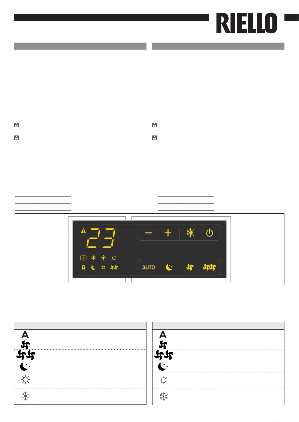
Conguração do modo de funcionamento
aquecimento/arrefecimento
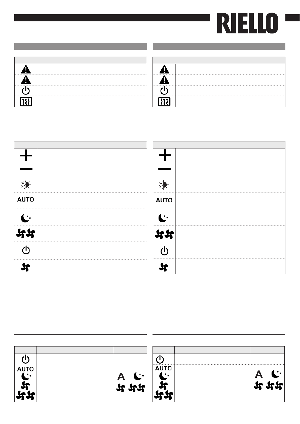
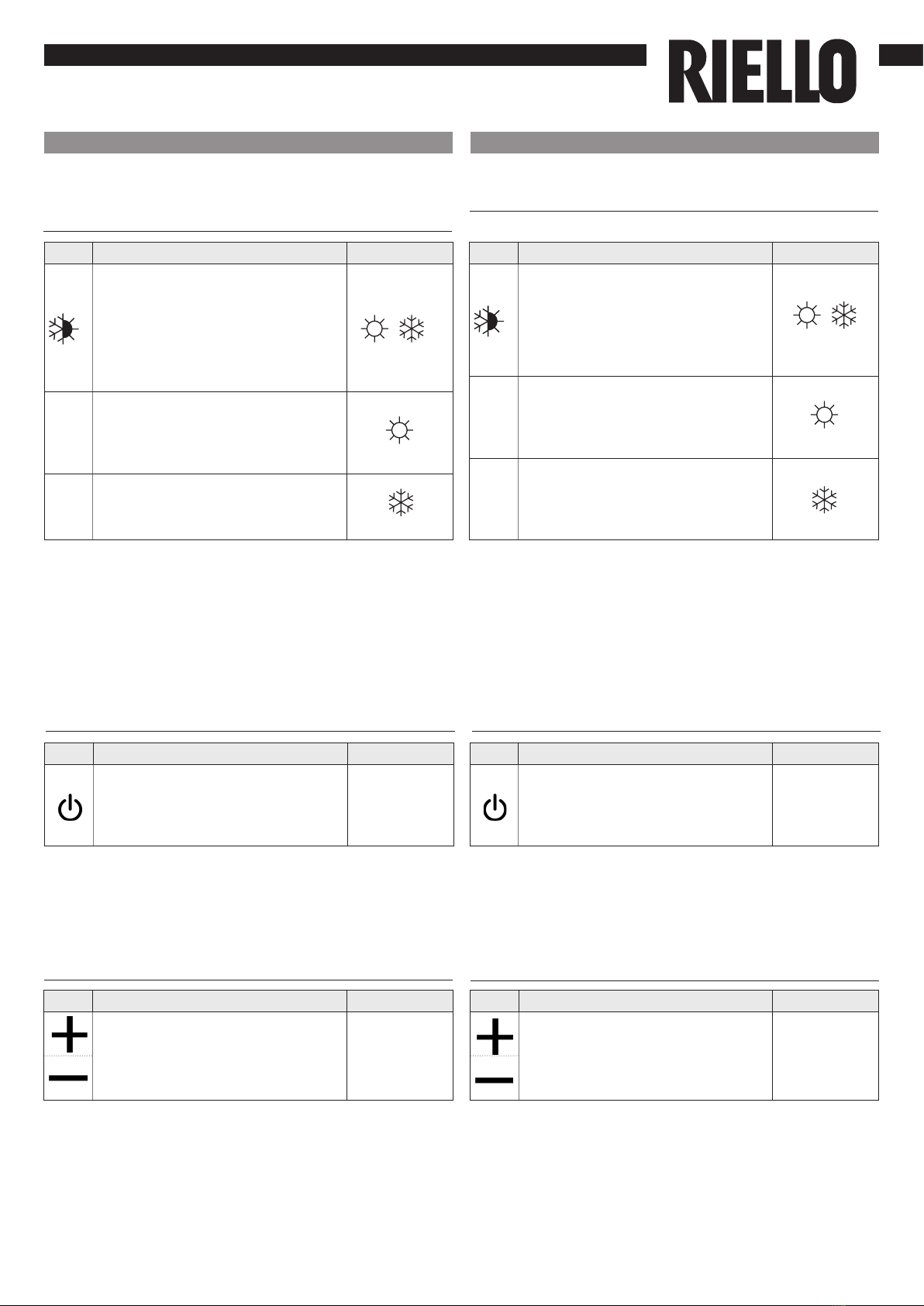
Tecla Operação Ecrã
Mantenha a tecla de Aquecimento/
Arrefecimento premida durante
cerca de 2 segundos para comutar
o modo de funcionamento entre
aquecimento e arrefecimento,
visível através do acendimento dos
2 símbolos de aquecimento ativo
ou de arrefecimento ativo.
No modo de aquecimento, o
símbolo está aceso com um
setpoint superior à temperatura
ambiente, desligados, ambos têm
um setpoint inferior .
No modo de arrefecimento, o símbolo
está aceso com um setpoint inferior
à temperatura ambiente, desligados,
ambos têm um setpoint inferior.
Stand-by
Tecla Operação Ecrã
Mantenha a tecla “mode/off” premida
durante cerca de 2 segundos. A ausência
de qualquer sinalização luminosa no
ecrã indica o modo de “stand-by“
(ausência de funcionamento).
De ligado para
desligado
O intervalo de regulação é de 16 a 28 °C, com uma resolução
de 1 °C mas os valores fora da escala de 5 °C e de 40 °C
também são permitidos (exceto no modo automático).
Dena estes valores apenas por períodos curtos e, em
seguida, regule a seleção para um valor intermédio.
Seleção da temperatura
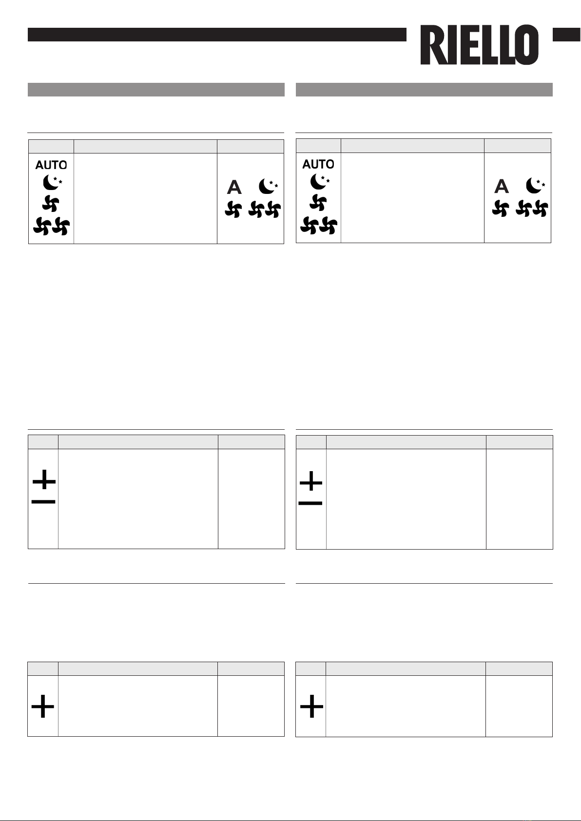
Tecla Operação Ecrã
Dena, utilizando as duas teclas
de aumentar e diminuir, o valor de
temperatura ambiente desejado,
exibido nos 2 dígitos do ecrã.
20
A intermitência de um dos 2 símbolos indica que a
temperatura da água (quente ou fria) não foi alcançada
e faz com que o ventilador pare até que a temperatura
atinja um valor adequado para satisfazer a solicitação. Se,
após a ligação, a placa detetar a sonda H2, o arranque
ocorre em condições normais com limites mínimos e
máximos da temperatura da água. A placa prevê também
o funcionamento sem sonda H2, nesse caso, os limites de
paragem do ventilador são ignorados.
If one of the 2 symbols ashes it means that the water
temperature (hot or cold) is not met and it makes the fan
stop until the water reaches the requested temperature. If
after powering the device the board detects the H2 probe,
the start-up will take place under normal conditions with
minimum and maximum thresholds. The board can also
operate without a H2 probe, case in which the fan stop
thresholds will be ignored.
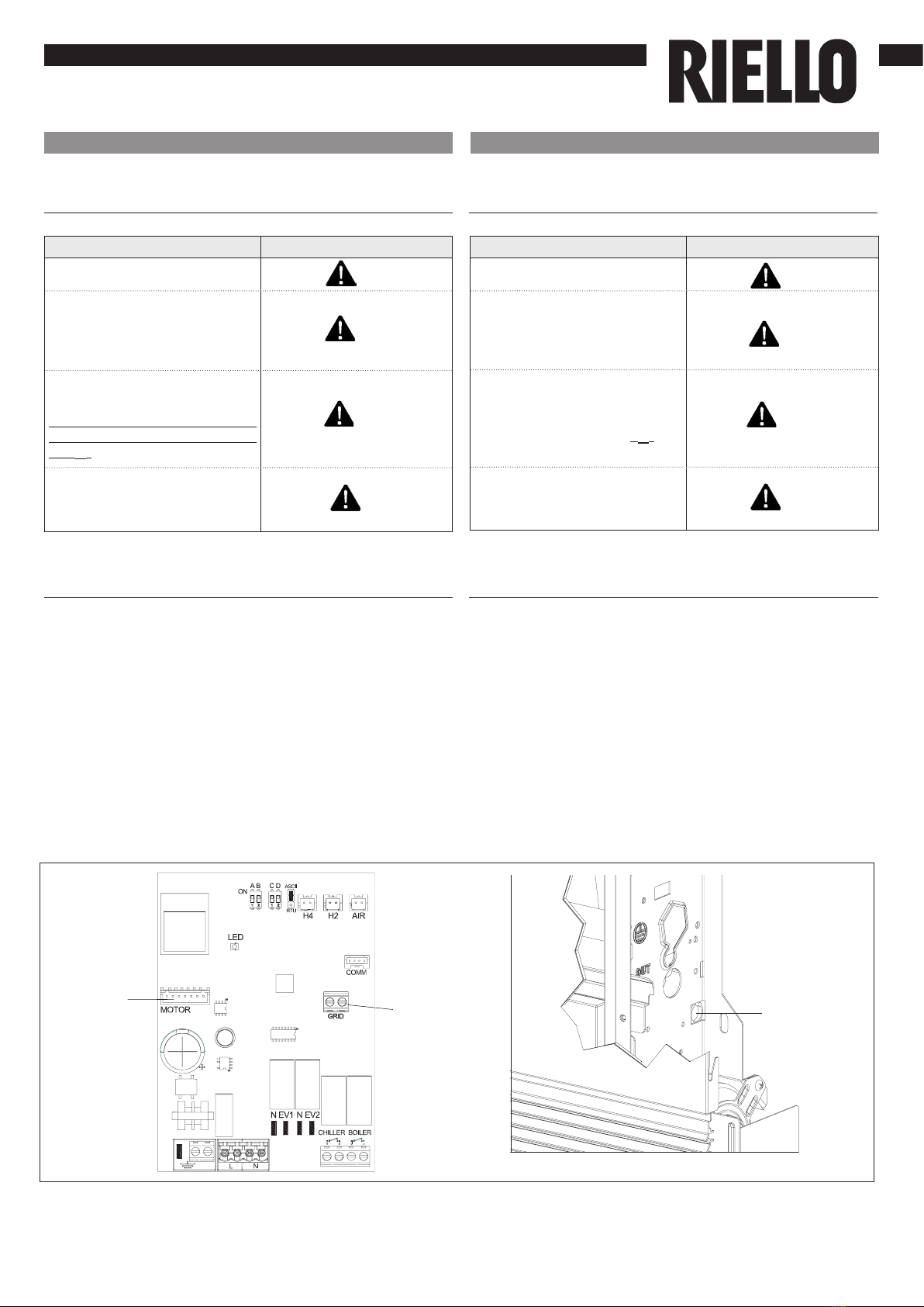
Quando o comando está neste modo de funcionamento,
garante uma proteção anticongelamento . Caso a
temperatura ambiente desça abaixo dos 5 °C, a saída da
eletroválvula de água é ativada.
When the control is in this operation mode, the anti-
freeze safety is secured. If the room temperature drops
below 5°C the solenoid valve output activates.
EN
Heating / cooling operation mode setting
Key Operation Display
Keep Heating / Cooling pressed
down for about 2 seconds to switch
the operation mode between
heating and cooling, shown
through the 2 active heating or
active cooling symbols which
appear.
In heating, the symbol is alight
when the setpoint is higher than
the room temperature, both are
switched off when the setpoint is
lower.
In cooling, the symbol is alight
when the setpoint is higher than
the room temperature, both are
switched off when the setpoint is
lower.
Stand by
Key Operation Display
Keep the mode/off key pressed for
about 2 seconds. The lack of any
light indicators from the display
indicates “standby” status (no
function).
From ON to
Off
The adjustment range goes from 15 to 30 °C, with 1°C
resolution, but over range values of 5°C and 40°C are also
consented (except when in auto mode).
Set these values only for brief periods, then adjust the
selection on an intermediate value.
Temperature selection
Key Operation Display
Set the desired temperature value,
shown on the 2 digits of the
display, with the aid of the two
increase and decrease keys.
20

HELIOTERM INVERTER
8Doc-0091334 Rev. 0
PT
Regulação da velocidade de ventilação
Tecla Operação Ecrã
Através da 4 teclas, é
possível selecionar os
modos de funcionamento
correspondentes às velocidades
do ventilador (automático,
noturno, mínimo e máximo). A
ativação da função é sinalizada
pelo acendimento do respetivo
símbolo no ecrã.
No modo automático, o ventilador efetua uma regulação
“passo a passo“ à medida que a temperatura ambiente se
aproxima do setpoint. A velocidade supersilent provoca uma
forte desumidicação no arrefecimento e apenas energia
radiante (com o ventilador desligado, eletroválvula e na
versão Plus microventiladores ativados) no aquecimento.
Congurando a velocidade máxima, obtém-se
imediatamente a potência máxima disponível no
aquecimento e no arrefecimento.
Uma vez alcançada a temperatura ambiente desejada,
é aconselhável selecionar um dos outros 3 modos de
funcionamento para obter um melhor conforto térmico e
acústico.
No “mínimo”, o número de rotações do ventilador é limitado
tanto no aquecimento, como no arrefecimento.
Key Operation Display
Attraverso i 4 tasti si
selezionano i modi di
funzionamento corrispondenti
alle velocità del ventilatore
(automatico, notturno, minimo
e massimo). L’attivazione
della funzione viene segnalata
dall’accensione del relativo
simbolo a display.
Bloqueio das teclas Key lock
20 segundos após a última ação, a luminosidade do painel
é especicamente reduzida para aumentar o conforto à
noite e no ecrã é exibida a temperatura ambiente.
No entanto, se esta luminosidade ainda o incomodar, é
possível desligar completamente o ecrã.
Redução mínima da luminosidade
Tecla Operação Ecrã
Premindo simultaneamente as
teclas + e - durante 3 segundos, é
ativado o bloqueio local de todas
as teclas, a conrmação é dada
pela exibição da indicação “bL”.
Todas as regulações cam
bloqueadas e quando uma tecla é
premida, aparece “bL”. Repetindo
a sequência, as teclas são
desbloqueadas.
bL
Tecla Operação Ecrã
Com o painel desligado, mantenha
a tecla + premida durante 5
segundos até aparecer a indicação
01. Com a tecla - coloque o valor
a 00 e aguarde 20 segundos para
vericar se cou bem congurado.
00
EN
Fan speed adjustment
In automatic mode, when the room temperature is about
to reach the setpoint the fan performs a regulation
“in steps“. The supersilent speed causes strong de-
humidication in cooling and a radiating-only function
(with fan off, and solenoid valve and for Plus versions
micro-fans on) in heating.
By setting maximum speed, the maximum distributable
power is immediately obtained both in heating as well as
cooling.
Once the desired environment temperature is reached, it
is advised to select one of the other 3 operation modes to
obtain the best thermal and acoustic comfort.
In “minimum“, the number of rotations of the fan will be
limited both in heating and in cooling.
After 20 seconds from the last action, the panel brightness
is purposely dimmed for greater comfort during night
time, and the room temperature is shown on the display.
If the brightness is still annoying one can switch the
display off completely.
General switch on
Key Operation Display
Press both + and - at the same
time for 3 seconds to activate
the local lock up of all keys, the
conrmation is represented by the
text bL appearing on the display.
The user will not be able to
perform any adjustment and the
text bL appears every time a key is
pressed. Repeat the sequence to
unlock the keys.
bL
Key Operation Display
With the panel off press the +
key for 5 seconds until the text 01
appears on the display. Use the -
key to bring the value to 00 and
wait 20 seconds to check for the
correct setting.
00

HELIOTERM INVERTER
9Doc-0091334 Rev. 0
PT
Desativação
Tecla Operação Ecrã
Mantenha a tecla “ON stand-
by” premida durante cerca de 2
segundos. A ausência de qualquer
sinalização luminosa no ecrã indica
o modo de “stand-by“ (ausência de
funcionamento).
De ligado para
desligado
Em caso de desligamentos sazonais ou para férias, proceda
da seguinte forma:
Desative o aparelho.
Posicione o interruptor geral da instalação em “Desligado”
Desligar por longos períodos
O comando garante uma proteção anticongelamento,
mesmo quando está em stand-by.
The control ensures anti-freeze safety even when set to
stand-by.
Regulação offset da sonda de temperatura
ambiente Room temperature probe offset
adjustment
Com a sonda de temperatura posicionada na parte inferior
do aparelho, pode acontecer que, em alguns casos, a
medição divirja da temperatura real. Através desta função,
é possível regular o valor medido visualizado no ecrã num
intervalo de +/- 10 °C em passos de 0,1 °C.
Utilize esta regulação com cuidado e só depois de ter
detetado efetivamente diferenças em relação à temperatura
ambiente real com um instrumento conável!!
In some cases the detected values might not represent
the real temperature due to the fact that the temperature
probe is located in the lower section of the device. Use
this function to adjust the measured value shown on the
display whitin a range +/- 10°C in 1°C steps.
Use this adjustment carefully and only after having found
deviations from the actual room temperature using a
reliable tool!
Tecla Operação Ecrã
Com o painel desligado, mantendo a
tecla - premida durante 5 segundos,
acede-se ao menu que permite
variar (através das teclas + e -) o
offset da sonda AIR visualizada no
ecrã de -10 para +10 °C em passos
de 1 °C. 20 segundos após a última
ação efetuada, o painel desliga-se e
a conguração é memorizada.
00
Tasto Operazione Display
With the panel off hold the - key
for 5 seconds to access the menu
from which you can adjust (using
the + and - keys) from -10 to +10
in 0.1K steps the offset of the AIR
probe displayed on the screen.
After 20 seconds from the last
action performed the panel turns
off and the setting is saved.
00
A função anticongelamento não está ativa The anti-freeze function is not on.
EN
Deactivation
Key Operation Display
Press the ON stand-by for about
2 seconds. When the device is in
“stand-by“ satus (no function)
there are no lights signals on the
display.
From On to
Off
In case of seasonal switch-offs or for holidays, proceed as
follows:
Deactivate the device.
Switch Off the main switch.
Shutting down for long periods

HELIOTERM INVERTER
10
C
DE
Doc-0091334 Rev. 0
PT
Sinalizações de erro
Erro
Ecrã
Avaria na sonda de
temperatura ambiente (AIR).
Problemas no motor do
ventilador (por exemplo,
bloqueio devido a corpos
estranhos, avaria no sensor
de rotação).
Avaria na sonda de deteção
da temperatura da água (H2).
Neste caso, certique-se de
que a sonda instalada é de
10 kΩ.
Acionamento do
microinterruptor da grelha S1
devido à operação de limpeza
do ltro.
E1
E2
E3
Gr
Se for necessário inverter a posição das ligações hidráulicas
da bateria do lado esquerdo para o lado direito do
aparelho, a caixa das ligações elétricas também é invertida,
mas como o motor do ventilador e o microinterruptor de
segurança da grelha estão vinculados na posição original,
é necessário utilizar o kit especíco 20069415 disponível
como acessório.
O cabo, equipado com conectores macho/fêmea, deve ser
ligado do lado direito do motor e do lado esquerdo do
engate rápido do motor presente na placa (ref.D).
Além disso, os dois terminais provenientes do
microinterruptor de segurança da grelha devem ser
estendidos e ligados do lado esquerdo do contacto GRID
presente na placa (ref.E).
Os cabos devem ser introduzidos, na parte traseira do
aparelho, no furo especíco (ref. C).
Ligação do motor nas versões com ligações
hidráulicas à direita
E1
E2
E3
Gr
EN
Error
Display
Room temperature probe
fault (AIR).
Fan motor fault (for example
jamming due to foreign
bodies or fault in the rotation
sensor).
Water temperature probe
failure (H2). In this case make
sure the probe has 10 kΩ.
Operation of the S1 grill
microswitch due to lter
clearing.
Error indications
In the event one needs to invert the position of the hydraulic
battery connections from the left side to the right side of
the device, the electric connections box is also inverted,
but since the fan motor and the grid safety microswitch
are constrained in the original position, one must use the
special kit 20069415, available as an accessory.
The cable, equipped with male/female connectors, must
be connected on the right side to the motor and on the
left side to the quick connector of the motor present on
the board (ref.D).
Also, the two terminals from the grid safety microswitch
must be extended and connected on the left side to
contact GRID present on the board (ref.E).
The cables are fed through the back of the device through
the specic hole (ref.C).
Water connection on the right side versions
motor connection

11 Doc-0091334 Rev. 0

HELIOTERM INVERTER
12
RIELLO S.p.A. - 37045 Legnago (VR)
tel. +39 0442 630111 - fax +39 0442 22378
www.riello.it
Doc-0091334 Rev. 0
PT
Sendo a nossa empresa orientada por uma política de melhoria contínua de toda a produção, as características
estéticas e dimensionais, dados técnicos, equipamentos e acessórios são suscetíveis de variação.
EN
As the manufacturer is constantly improving its products, the aesthetic or dimensional features, the technical data,
the equipment and accessories indicated could be subject to variations.
Table of contents
Other Riello Control Panel manuals

Riello
Riello Touchscreen N User manual

Riello
Riello CPD 30 User manual

Riello
Riello 4030011 User manual

Riello
Riello Wired Touch panel User manual

Riello
Riello 20147241 User manual

Riello
Riello 20081467 User manual

Riello
Riello CBD 20 PLUS User manual

Riello
Riello RIELLOtech CLIMA TOP User manual

Riello
Riello RIELLOtech PRIME User manual

Riello
Riello RIELLOtech CLIMA TOP 4031065 User manual