Riello CPD 30 User manual

HELIOTERM INVERTER
Cod. 20073378 Rev. 0
IT
1. Avvertenze preliminari
Questa istruzione è parte integrante del libretto
dell’apparecchio sul quale viene installato il KIT. A tale
libretto si rimanda per le AVVERTENZE GENERALI e per le
REGOLE FONDAMENTALI DI SICUREZZA.
CPD 30 - PANNELLO DI COMANDO A
PARETE
2. Versioni
Codici
20069382
CPD 30 - Pannello di comando a parete
In alcune parti del libretto sono utilizzati i simboli:
ATTENZIONE= per azioni che richiedono particolare
cautela ed adeguata preparazione.
VIETATO= per azioni che non devono essere
assolutamente eseguite.
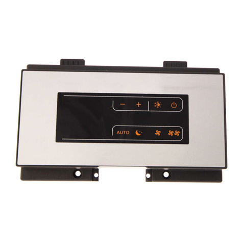
Il controllo remoto a muro è un termostato elettronico
(dotato di sonda di temperatura) con possibilità di
controllo su uno o più apparecchi (fino ad un massimo di
30) dotati di comando elettronico per remotizzazione CSD
30.
Installare il controllo remoto a muro CPD 30 lontano
da porte e/o finestre e da fonti di calore (caloriferi,
ventilconvettori, fornelli, raggi diretti del sole), su pareti
interne e ad un’altezza di circa 1,5 m dal pavimento.
Il controllo remoto a muro è presente all’interno della
confezione già assemblato, pertanto seguire le seguenti
istruzioni per il fissaggio:
aprire i coperchi facendo leva sui due dentini sporgenti
con un cacciavite (E e F);
svitare le due viti di fissaggio della scheda elettronica
alla base del controllo (rif. D);
utilizzare la base del controllo (rif. A) per tracciare a
muro i punti di fissaggio (utilizzare i due fori opposti);
forare la parete;
passare i cavi elettrici attraverso le finestre presenti sulla
base;
fissare la base del controllo alla parete utilizzando viti e
tasselli adeguati (rif. B).
A corredo viene fornita una scheda alimentatore da 230/12
VDC (rif. H ) per l’alimentazione elettrica del controllo
che va installata nella scatola dei collegamenti (rif.
G) presente a bordo di uno degli apparecchi dotati di
comando elettronico per remotizzazione CSD 30.
3. Montaggio e connessioni pannello di
controllo remoto a muro
EN
1. Preliminary instructions
This instruction booklet is an integral part of the manual
of the device on which you install the kit. In that manual,
please refer to the WARNINGS and the BASIC SAFETY RULES.
CPD 30 - CONTROL PANEL WALL MOUNTED
2. Versions
Codes
20069382
CPD 30 - Control panel wall mounted
The following symbols are used in this publication:
WARNING = actions requiring special care and
appropriate training.
DO NOT = actions that MUST ON NO ACCOUNT be
carried out.
The wall-mounted is an electronic thermostat (fitted with
temperature probe) with the possibility of controlling
one or more cooler-convector/cooler-radiators (up to
a maximum of 30) equipped with electronic control for
allowing remote control CSD 30.
Install the wall-mounted remote control CPD 30 away
from doors or windows and sources of heat (heaters,
convectors, stoves, direct sunlight), on internal walls at
a height of about 1.5 m from the floor.
The wall-mounted remote control is already assembled in
the package so follow the following mounting instructions:
open the cover by levering the two lower lugs with a
screwdriver (ref. E and F);
unscrew the two fixing screws on the electronic boards
at the base of the control (ref. D);
use the base of the control (ref. A) to trace the fixing
point on the wall (use the two opposite holes);
drill the holes in the wall;
route the electric wires through the windows on the
base;
fix the base of the control to the wall using suitable
plugs (ref. B).
A 230/12 VDC PCB transformer (ref. H) is supplied for the
electric power supply of the control that should be
installed in the connection box (ref. G) on board of one of
the devices equipped with electronic control for allowing
remote control CSD 30.
3. Fitting and connecting the wall-
mounted remote control panel

HELIOTERM INVERTER
Cod. 20073378 Rev. 0
A
B
C
E
D
F
H
G
IT
Collegare la linea RS485 del controllo remoto a muro ad
uno o più (fino ad un massimo di 30) apparecchi dotati di
comando elettronico per remotizzazione CSD 30 mediante
cavo bipolare adatto per connessione seriale RS485
tenendolo separato dai cavi d’alimentazione elettrica.
Eseguire un tracciato in modo da ridurre al minimo la
lunghezza delle derivazioni;
terminare la linea con la resistenza da 120 ohm in
dotazione;
non effettuare collegamenti a “stella”;
il collegamento con il cavo RS485 è polarizzato, rispettare
le indicazioni “A” e “B” su ogni periferica collegata
(per la connessione utilizzare preferibilmente un cavo
bipolare schermato con sezione minima di 0,35 mm2);
Collegare i terminali di alimentazione 230V della scheda
alimentatore 230/12VDC INN-FR-B3 ai morsetti L ed N
della scheda INN-FR-41 del comando CSD 30.
Collegare i terminali di alimentazione + e - SUPPLY
del controllo a muro CPD 30 alla scheda alimentatore
230/12VDC rispettandone la polarità.
Alimentare il controllo remoto unicamente con la
scheda alimentatore da 230/12 VDC in dotazione.
4. Connessioni
EN
Connect the RS485 line of the wall-mounted remote
control to one or more (up to a maximum of 30) units
equipped with electronic remote control CSD 30 through a
bipolar cable suitable for RS485 serial connection, keeping
it separate from power supply cables.
Chase out the wall in order to minimise the length of
the leads;
complete the line with the 120 ohm resistance supplied;
do not make “star” connections;
the connection with cable RS485 is polarised, observe
the indications “A” and “B” on each peripheral device
connected (for the connection it is preferable to use a
bipolar shielded cable with a minimum section of 0.35
mm2);
Connect the terminals of the 230V power supply of power
supply board 230/12VDC INN-FR-B3 to clamps L and N of
board INN-FR-41 of control CSD 30;
Connect the power SUPPLY terminals + and - of the wall-
mounted control CPD 30 to the 230/12VDC power supply
board, observing the polarity.
Power the remote control solely with the 230/12 VDC
power supply board provided.
4. Connections

HELIOTERM INVERTER
Cod. 20073378 Rev. 0
IT
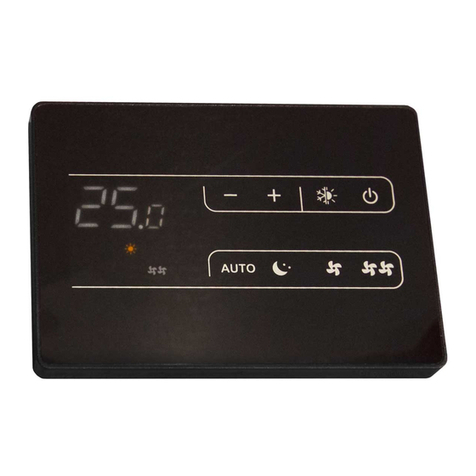
Il comando remoto a muro CPD 30 è un termostato
elettronico dotato di sonda di temperatura ambiente che
permette di controllare uno o più (fino ad un massimo
di 30) ventilradiatori/ventilconvettori in broadcast (con la
trasmissione simultanea dei comandi) dotati di comando
elettronico per remotizzazione CSD 30.
Il pannello comandi è dotato di memoria, per cui tutte
le impostazioni non andranno perse né in caso di
spegnimento né in caso di mancanza di tensione.
Eventuali anomalie dei singoli terminali connessi non
vengono segnalate dal pannello a muro.
Attraverso la sonda di temperatura garantisce una
sicurezza antigelo anche quando è posto in stand-by.
Dopo un periodo di 20 secondi dall’ultima azione la
luminosità del pannello viene ridotta e sul display
viene visualizzata la temperatura ambiente. Alla
pressione di un qualsiasi tasto viene ripristinata la
massima luminosità.
L’ingresso SW2 va connesso ad un contatto pulito (non in
tensione) e alla chiusura del contatto il pannello di controllo
CPD 30 e tutti i comandi elettronici per remotizzazione CSD
30 collegati CPD 30 vengono spenti.
5. Descrizione
6. Connessione ingresso contatto presenza CP
EN
The wall remote control CPD 30 is an electronic thermostat,
equipped with an environment temperature probe which
allows to control one or more (up to a maximum of 30)
cooler-radiators/fan coils through broadcasting (with
simultaneous command transmission) equipped with
electronic command for CSD 30 remote controlling.
The control panel has function memory, so all the
settings are not lost in case of switch off or in the event
of power failure.
Eventual anomalies of the single connected terminals
are not indicated by the wall panel.
Thanks to the temperature probe, it guarantees anti-
freeze safety, even when in stand-by.
After a period of 20 seconds from the last action, the
panel light dims and the display shows the environment
temperature. Maximum luminosity is restored when
pressing any key.
The SW2 input must be connected to a free contact (not
powered) and, when the contact is closed the remote
control panel CPD 30 and all the electronic control for
allowing remote control CSD 30 connected will be switched
off.
5. Description
6. CP presence contact input connection

HELIOTERM INVERTER
Cod. 20073378 Rev. 0
IT
Pannello comando a muro
Pannello a bordo macchina per remotizzazione
Sul display vengono inoltre visualizzati gli stati e gli
eventuali allarmi attraverso gli 8 specifici simboli:
7. Display
Icone
funzionamento automatico selezionato
funzionamento silenzioso selezionato
massima velocità ventilazione selezionata
funzionamento notturno selezionato
riscaldamento attivo
raffrescamento attivo
supervisione da webserver attiva
indicazione allarme
Led
Led Verde: Segnala il funzionamento
dell’apparecchio. Lampeggia in caso di
anomalie.
EN
Wall command panel
Wall command panel
Wall command panel
Panel on board machine for remote controlling
The display also shows status and eventual alarms through
the 8 specific symbols:
7. Display
Icons
automatic function selected
silent function selected
maximum ventilation speed selected
night function selected
active heating
active cooling
webserver supervision active
alarm signal
Led
Green Led: Indicated device operation. Flashes
in case of anomalies.

HELIOTERM INVERTER
Cod. 20073378 Rev. 0
IT
Pannello comando a muro
Pannello a bordo macchina per remotizzazione
Le varie funzioni vengono impostate attraverso 8 tasti
retroilluminati:
Per la gestione dell’apparecchio attraverso il pannello di
controllo questo deve essere collegata alla rete elettrica.
Nel caso sia stato previsto un interruttore generale sulla
linea elettrica di alimentazione, questo deve essere
inserito.
Accendere l’impianto inserendo l’interruttore generale
Per attivare l’apparecchio
8. Funzione dei tasti
9. Accensione generale
10. Attivazione
Icone
Temp + consente di aumentare la temperatura
impostata
Temp - consente di diminuire la temperatura
impostata
Riscaldamento / Raffrescamento : consente
di commutare il modo di funzionamento tra
riscaldamento e raffrescamento
Rende completamente automatica la
regolazione della velocità di ventilazione tra
un valore minimo ed un valore massimo
Funzionamento notturno : viene limitata la
velocità di ventilazione ad un valore molto
contenuto e la temperatura impostata viene
variata automaticamente
Max: consente di impostarela massima velocità
di ventilazione
ON/Stand-By: Consente di attivare l’apparecchio
o di metterlo in condizione di attesa.
Silent : consente di limitare la velocità
di ventilazione ad un valore massimo più
contenuto.
Tasto
ON/Stand-By:Consentedi attivare l’apparecchio
o di metterlo in condizione di attesa.
Tasto Operazione Display
Premere il tasto ON stand-by Spento
Selezionare uno dei 4modi di
funzionamento premendo il
relativo tasto.
EN
Wall command panel
Panel on board machine for remote controlling
The various functions are set with the 8 backlit keys:
To manage the device through the control panel, it must
be connected to the mains.
In case of a general switch on the mains supply line, it
must be switched on.
Switch on the system with the main switch
To activate the device
8. Key function
9. General switch on
10. General switch on
Icons
Temp + allows to increase set temperature.
Temp - allows to decrease set temperature.
Heating / Cooling : allows to switch operation
mode between heating and cooling.
Makes ventilation speed adjustment completely
automatic between a minimum and maximum
value.
Night function : ventilation speed is limited to a
very contained value, and the set temperature
is automatically changed.
Max: allows to set the maximum ventilation
speed.
ON/Stand-By: Allows to activate the device or
to put it in standby.
Silent : allows to limit the ventilation speed to
a more contained maximum value.
Key
ON/Stand-By: Allows to activate the device or
to put it in standby.
Key Operation Display
Press ON standby. Off
Select one of the 4 operation
modes by pressing the
relative key.

HELIOTERM INVERTER
Cod. 20073378 Rev. 0
IT
Il lampeggio di uno dei 2 simboli indica che la temperatura
dell’acqua (calda o fredda) non è soddisfatta e comporta
l’arresto del ventilatore finché la temperatura non
raggiunge un valore adeguato a soddisfare la richiesta.
Se la temperatura dell’acqua non raggiunge un valore
idoneo al funzionamento richiesto, dopo 10minuti il
comando va in blocco, compare il simbolo di indicazione
allarme E5. Lo sblocco avviene automaticamente dopo 45
minuti o manualmente premendo uno degli 8 tasti.
11. Impostazione modo di funzionamento
riscaldamento / raffrescamento
Tasto Operazione Display
Tenere premuto il tasto
Riscaldamento / Raffrescamento
per circa 2 secondi per commutare
il modo di funzionamento tra
riscaldamento e raffrescamento
visibile attraverso l’ accensione dei
2 simboli riscaldamento attivo o
raffrescamento attivo.
In riscaldamento il simbolo è
acceso con setpoint superiore alla
temperatura ambiente, spenti
entrambi con setpoint inferiore.
In raffrescamento il simbolo è
acceso con setpoint inferiore alla
temperatura ambiente, spenti
entrambi con setpoint superiore.
Nelle versioni a 4 tubi, con il sistema
di regolazione raffrescamento/
riscaldamento automatico attivato
I'accensione contemporanea dei 2
simboli indica il raggiungimento del
setpoint (banda neutra).
Quando il comando si trova in questo modo di
funzionamento garantisce una sicurezza antigelo.Nel caso
in cui la temperatura ambiente scenda al di sotto dei 5°C
vengono attivate le uscite elettrovalvola acqua calda e
consenso caldaia.
12. Stand By
Tasto Operazione Display
Impostare con l'ausilio dei due tasti
aumento e diminuzione il valore di
temperatura desiderato in ambiente
visualizzato sui 3 digit del display.
Off
Il range di regolazione va da 16 a 28 °C, con risoluzione di
0,5°C, ma sono consentiti anche i valori fuori scala di 5°C
e di 40°C.
Impostare tali valori solo per brevi periodi e poi regolare la
13. Selezione della temperatura
Tasto Operazione Display
Impostare con l'ausilio dei due tasti
aumento e diminuzione il valore di
temperatura desiderato in ambiente
visualizzato sui 3 digit del display.
EN
Flashing of one of the 2 symbols indicates that the water
temperature (hot or cold) is not satisfactory, and the
ventilator is stopped until the temperature does not reach
an adequate value to satisfy the request.
If the water temperature does not reach a suitable
value for the requested operation, after 10 minutes, the
command is blocked, the E5 alarm indicator symbol
appears. Unlocking occurs automatically after 45 minutes,
or manually by pressing one of the 8 keys.
11. Heating / cooling operation mode
setting
Key Operation Display
Keep Heating / Cooling pressed down
for about 2 seconds to switch the
operation mode between heating
and cooling, shown through the
2 active heating or active cooling
symbols which appear.
When heating, the symbol is switched
on when the set point is higher than
the environment temperature; they
are both switched off when the set
point is lower.
When cooling, the symbol is switched
on when the set point is lower than
the environment temperature; they
are both switched off when the set
point is higher.
In the 4 pipe version, with
activated automatic cooling/heating
adjustment system, the simultaneous
switch on of the 2 symbols indicates
reaching of a set-point (neutral
band).
When the command is in this operation mode, it guarantees
anti-freeze safety. In case the environment temperature
should drop below 5 °C, the hot water solenoid valve and
boiler consent outputs are activated.
12. Stand By
Key Operation Display
Keep the ON standby key pressed for
about 2 seconds. The lack of any light
indicators from the display indicates
“standby” status (no function).
Off
The adjustment range goes from 16 to 28°C, with 0.5°C
resolution, but over range values of 5°C and 40°C are also
consented.
Set these values only for brief periods, then adjust the
13. Temperature selection
Key Operation Display
Set the desired temperature value, shown
on the 3 digits of the display, with the aid
of the two increase and decrease keys.
HELIOTERM INVERTER
Cod. 20073378 Rev. 0
IT
selezione su un valore intermedio.
Il comando è molto preciso, portarlo sul valore desiderato
ed attendere che il comando esegua la regolazione in base
alla effettiva temperatura ambiente rilevata.
La regolazione della velocità di ventilazione avverrà
automaticamente tra un valore minimo ed un valore
massimo, secondo la effettiva distanza della temperatura
ambiente dal setpoint impostato in base ad un algoritmo
di tipo PI.
14. Funzionamento automatico
Tasto Operazione Display
Tener premuto il tasto AUTO.
L’attivazione della funzione viene
segnalata dall'accensione del relativo
simbolo a display
La velocità di ventilazione viene limitata ad un valore
massimo più contenuto.
15. Funzionamento silenzioso
Tasto Operazione Display
Tener premuto il tasto Silent.
L’attivazione della funzione viene
segnalata dall'accensione del relativo
simbolo a display
Selezionando questo modo di funzionamento, viene
limitata la velocità di ventilazione ad un valore molto
contenuto e la temperatura impostata viene variata
automaticamente come segue:
diminuita di 1° C dopo un ora ed un ulteriore grado dopo
2 ore nella funzione riscaldamento;
aumentata di 1°C dopo un ora e un ulteriore grado dopo
2 ore nella funzione raffreddamento.
16. Funzionamento notturno
Tasto Operazione Display
Tener premuto il tasto Funzionamento
notturno. L’attivazione della funzione
viene segnalata dall'accensione del
relativo simbolo a display
Con questa modalità di funzionamento, si ottiene
immediatamente il massimo della potenza erogabile sia in
riscaldamento che in raffreddamento.
Una volta raggiunta latemperatura ambiente desiderata è
consigliabile selezionare uno degli altri 3 modi di funzionamento
per ottenere un miglior confort termico ed acustico.
17. Funzionamento alla massima velocità
di ventilazione
Tasto Operazione Display
Tener premuto il tasto Funzionamento
Max. L’attivazione della funzione
viene segnalata dall'accensione del
relativo simbolo a display
EN
selection on an intermediate value.
The command is very precise; reach the desired value and
wait for the command to carry out the adjustment based
on the effective environment temperature detected.
Ventilation speed adjustment will occur automatically
between a minimum and a maximum value, according
to the effective distance of the environment temperature
from the set point, based on a PI type algorithm.
14. Automatic function
Key Operation Display
Keep the AUTO key pressed. Activation
of the function is indicated by the
relative symbol appearing on the
display.
The ventilation speed is restricted to a more contained
maximum value.
15. Silent function
Key Operation Display
Keep the Silent key pressed. Activation
of the function is indicated by the
relative symbol appearing on the
display.
By selection this operation mode, the ventilation speed is
limited to a very contained value, and the set temperature
is automatically changed as follows:
decreased by 1 °C after one hour and an additional
degree after 2 hours in heating function;
increased by 1 °C after one hour and an additional degree
after 2 hours in cooling function.
16. Night function
Key Operation Display
Keep the Night operation key pressed.
Activation of the function is indicated
by the relative symbol appearing on
the display.
With this mode of operation, the maximum distributable
power is immediately obtained both in heating as well as
cooling.
Once the desired environment temperature is reached, it
is advised to select one of the other 3 operation modes to
obtain the best thermal and acoustic comfort.
17. Operation at maximum ventilation
speed
Key Operation Display
Keep the Max operation key pressed.
Activation of the function is indicated
by the relative symbol appearing on
the display.

HELIOTERM INVERTER
Cod. 20073378 Rev. 0
RIELLO S.p.A. - 37045 Legnago (VR)
tel. +39 0442 630111 - fax +39 0442 22378
www.riello.it
IT
18. Blocco tasti
Tasto Operazione Display
Premendo contemporaneamente
i tasti ON stand-by e Temp per 1
secondo si attiva il blocco locale di
tutti i tasti, la conferma è data dalla
visualizzazione di Loc.
Tutte le regolazioni vengono inibite
all’utente e alla pressione di qualsiasi
tasto compare Loc. Ripetendo la
sequenza si ottiene lo sblocco dei
tasti.
Il comando garantisce una sicurezza antigelo anche
quando è posto in stand-by.
In caso di spegnimenti stagionali o per vacanze procedere
come segue:
Disattivare l’apparecchio.
Posizionare l’interruttore generale impianto su Spento.
La funzione antigelo non è attiva.
19. Disattivazione
20.Spegnimento per lunghi periodi
Tasto Operazione Display
Tenere premuto il tasto ON stand-by
per circa 2 secondi. La mancanza di
qualsiasi segnalazione luminosa dal
display identifica lo stato di "stand-
by" (assenza di funzione).
Spento
Poiché l’Azienda è costantemente impegnata nel continuo perfezionamento di tutta la sua produzione, le
caratteristiche estetiche e dimensionali, i dati tecnici, gli equipaggiamenti e gli accessori, possono essere soggetti
a variazione.
EN
18. Key lock
Key Operation Display
By pressing ON standby and Temp
simultaneously for 1 second, the
local block of all keys is activated,
confirmed by the display of Loc.
All adjustments are prevented to the
user, and Loc. appears when pressing
any key. To unlock the keys, repeat
the sequence.
The command guarantees anti-freeze safety even when in
standby.
In caso di spegnimenti stagionali o per vacanze procedere
come segue:
Disattivare l’apparecchio.
Posizionare l’interruttore generale impianto su Spento.
La funzione antigelo non è attiva.
19. Deactivation
20.Switch off for long periods
Key Operation Display
Keep the ON standby key pressed for
about 2 seconds. The lack of any light
indicators from the display indicates
“standby” status (no function).
Off
As the manufacturer is constantly improving its products, the aesthetic or dimensional features, the technical data,
the equipment and accessories indicated could be subject to variations.
This manual suits for next models
1
Table of contents
Other Riello Control Panel manuals

Riello
Riello CPD 35 User manual

Riello
Riello Wired Touch panel User manual

Riello
Riello CPD 35 User manual

Riello
Riello RIELLOtech CLIMA TOP 4031065 User manual

Riello
Riello Touchscreen N User manual

Riello
Riello 20147241 User manual

Riello
Riello NexSirius User manual

Riello
Riello CBD 20 PLUS User manual

Riello
Riello Thermital TBOX BASIC ACS Technical manual

Riello
Riello 4030011 User manual