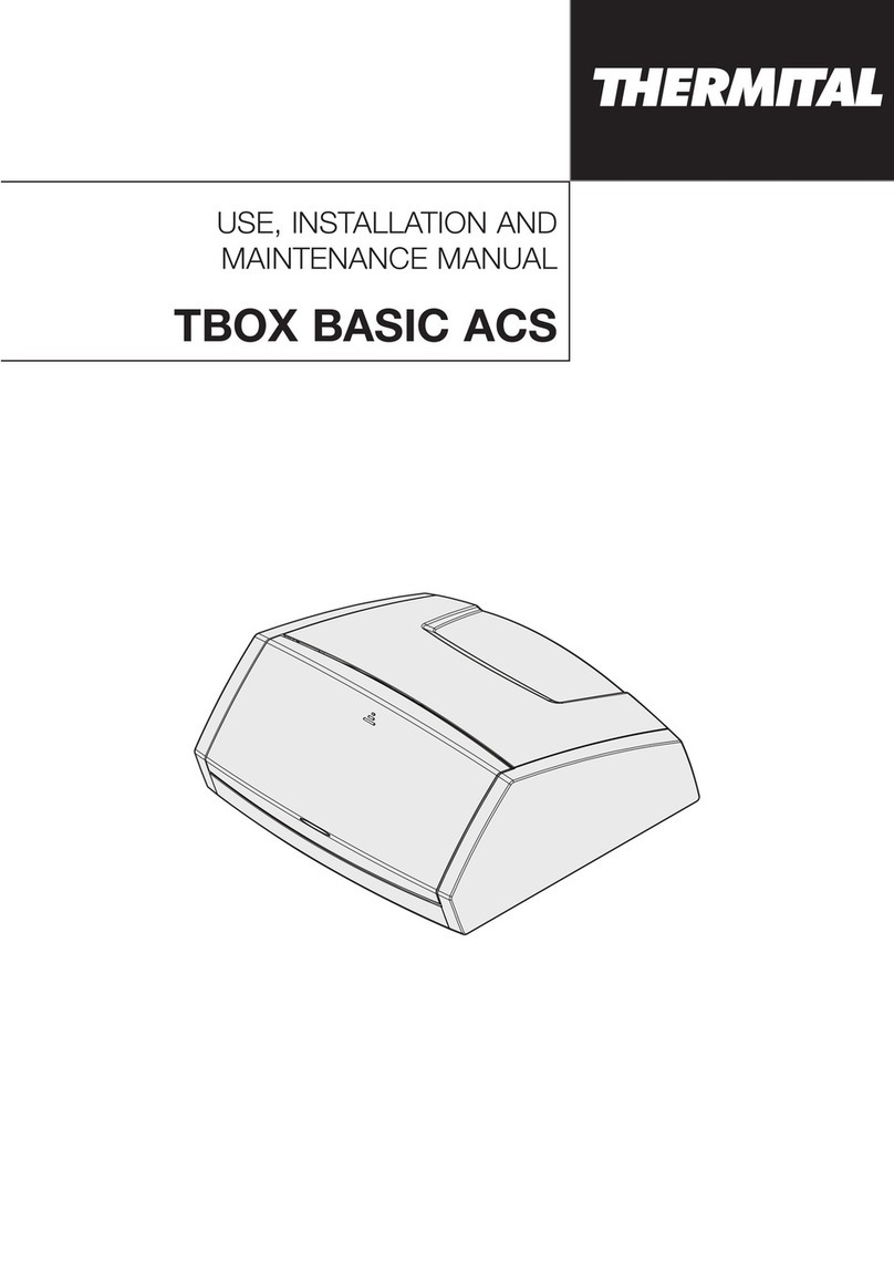
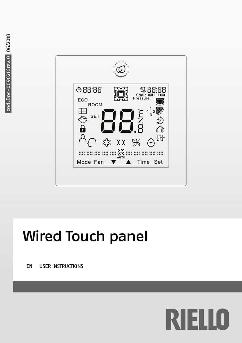
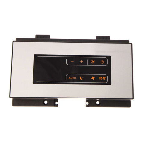
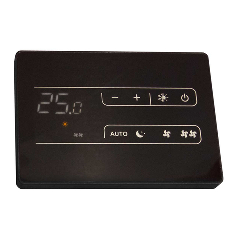
Riello 20147241 User manual

HELIOTERM INVERTER
Doc-0089524 Rev. 4
1
1 2 3 4
IT
1. Avvertenze preliminari
Questa istruzione è parte integrante del libretto
dell’apparecchio sul quale viene installato il KIT. A tale
libretto si rimanda per le AVVERTENZE GENERALI e per le
REGOLE FONDAMENTALI DI SICUREZZA.
Il pannello di comando cod. 20147241 è un termostato
elettronico a microprocessore per installazione ad incasso
secondo lo standard 503E, che collegato alla scheda
controllo per connessione remota cod. 20116412, permette
di gestire l’apparecchio attraverso:
Pulsante Start-Stop
Pulsante selezione velocità
Selezione estate/inverno
Uscita a tre velocità 230V~
Uscita per due elettrovalvole a 230V~
Il dispositivo possiede una memoria non volatile che
consente così di eseguire diverse configurazioni per ogni
funzione di base. Campo di regolazione da 6°C a 30°C.
PANNELLO DI COMANDO AD INCASSO
In alcune parti del libretto sono utilizzati i simboli:
ATTENZIONE= per azioni che richiedono particolare
cautela ed adeguata preparazione.
VIETATO= per azioni che non devono essere
assolutamente eseguite.
2. Versioni
Codici
20147241
Pannello di controllo remoto ad incasso
3. Contenuto del kit
1 Pannello di comando ad incasso 1
2 Viti di fissaggio 2
3 Istruzioni per il montaggio 1
4 Mascherina di ricambio 2
Il termostato è adatto esclusivamente all’installazione
nelle placche BTicino serie LIVING, AVE Sistema 45, Vimar
serie IDEA.
Il dispositivo deve essere installato da personale
qualificato, nel rispetto delle norme di sicurezza e
delle disposizioni di legge vigenti. Togliere la tensione
all’impianto prima di effettuare o intervenire su
qualsiasi collegamento elettrico.
EN
1. Preliminary instructions
This instruction booklet is an integral part of the manual
of the device on which you install the kit. In that manual,
please refer to the WARNINGS and the BASIC SAFETY RULES.
The following symbols are used in this publication:
WARNING = actions requiring special care and
appropriate training.
DO NOT = actions that MUST ON NO ACCOUNT be
carried out.
2. Versions
3. Kit composition
RECESSED CONTROL PANEL
Codes
20147241
Remote control panel for recessed installation
1 Recessed control panel 1
2 Fixing screws 2
3 Installation instructions 1
4 Replacement mask 2
The control panel code 20147241 is an electronic
microprocessor thermostat for recessed installation
according to the 503E standard, which is connected to the
control card for remote connection code 20116412, allows
managing the appliance through:
Start-Stop button
Speed selection button
Summer / winter selection
230V ~ three-speed output
Output for two 230V ~ electrovalves
The device has a non-volatile memory that allows it to
perform different configurations for each
basic function.
Adjustment range from 6 ° C to 30 ° C.
The thermostat is only suitable for installation with
BTicino LIVING Series,AVE Sistema 45, and Vimar IDEA
Series cover plates.
Only qualified staff can install the device, according
to the Legislation. Disconnect the main circuit breaker
before making any electrical connections.

HELIOTERM INVERTER
Doc-0089524 Rev. 4
2
1
23
4
5
IT
4. Posizionamento
Installare il regolatore lontano da fonti di calore
(caloriferi, raggi del sole, cucine) e da porte/finestre
ecc.
Installare il regolatore a 1,5 m dal pavimento, su
pareti interne, sigillando il tubo di uscita dei cavi di
collegamento.
Installare il regolatore in corrispondenza della
lunghezza massima del cavo di collegamento
L’installazione deve essere effettuata da personale
qualificato
Il regolatore si trova all’interno della confezione già
montato ed agganciato all’apposita armatura fornita di
serie.
All’interno della confezione è riportata una mascherina
di colore bianco. Per la sostituzione del frontale seguire le
istruzioni della immagine sottostante.
EN
4. Positioning
Install the regulator far away from heat sources
(radiators, sunlight, kitchens) and from doors/windows
etc.
Install the regulator 1.5 m from the floor, on internal
walls, sealing the connection cable exit tube.
Install the regulator with the connection cable at its
maximum length.
Installation must be carried out by qualified personnel.
The regulator in the package is already fitted and hooked
to the dedicated housing supplied as standard.
Inside the box there is a white frontal mask. To replace the
front panel follow the instructions in image below.

HELIOTERM INVERTER
Doc-0089524 Rev. 4
3
1,5 m
SI
NO
NO
A
B
1
2
P
Ai fini del fissaggio, basterà semplicemente eseguire le
seguenti operazioni:
Effettuare i collegamenti come descritto al capitolo
“Collegamenti” e nel manuale di installazione
dell’apparecchio.
Alloggiare il regolatore e relativa armatura nella scatola
a tre moduli precedentemente incassata nel muro e
fissare (in posizione A) mediante le viti fornite a corredo
Montare a pressione la PLACCA desiderata (P).
L’armatura è stata studiata per montare sul prodotto una
serie di PLACCHE ben specifiche:
BTicino serie LIVING
AVE serie sistema 45
Vimar serie IDEA
In base alla placca selezionata è necessario, in alcuni casi,
intervenire sulle quattro linguette laterali.
Per montare la placca della BTicino serie Living Classic 4713-
-, occorre asportare le linguette evidenziate nel disegno
con la lettera B all’altezza del punto 1.
Se si utilizza una placca della Vimar serie Idea è necessario
tagliare le linguette B all’altezza del punto 2 posto a circa
1 mm dall’accenno di taglio situato sulle linguette stesse.
Infine se si utilizza una placca Ave non è necessaria alcuna
operazione di adattamento.
In order to fix it, therefore, only the following operations
are necessary:
Connect as described in the “Connections” section and
in the installation manual for the device.
Position the regulator and its housing in the three-
module casing previously recessed in the wall and fix
the assembly (in A position) using the screws provided.
Press to fit the desired COVER PLATE (P).
The housing has been designed for fitting a very specific
series of COVER PLATES on the product:
BTicino LIVING series
AVE sistema 45 series
Vimar IDEA series
According to the selected frame it is necessary, in some
cases, to operate on the four side wings.
For installation with the BTicino Living, Classic 4713--,
series frame, side wings B must be cut along line 1.
If using a Vimar frame (Idea series) it is necessary to cut
the side wings B along line 2 in.
With an Ave Sistema 45 frame no adapting operation is
required.
IT EN

HELIOTERM INVERTER
Doc-0089524 Rev. 4
4
H2
LED
DATA I/O
H4 H2
KE
KE
KE
IT
5. Collegamenti
Effettuare i collegamenti alla scheda di controllo per
connessione remota montata sull’apparecchio seguendo
quanto indicato in figura.
L-N Alimentazione elettrica 230V-50Hz
EV Ingresso consenso
V1 Velocità massima ventilatore (1500 rpm)
V2 Velocità media ventilatore (1100 rpm)
V3 Velocità minima ventilatore (680 rpm)
V4 Velocità supersilent (400 rpm)
Y1 Elettrovalvola acqua (uscita in tensione a 230V/
50Hz 1A)
Y2 Comando pannello aspirazione mobile (uscita in
tensione a 230V/ 50Hz 1A)
RS Cablaggio versione Plus (da connettere a cura
dell’installatore)
HRS Sonda acqua (10 kΩ)
M1 Motore ventilatore DC inverter
KE Relè AUSILIARIO estate (non fornito a corredo, a
cura installatore)
L-N 230V-50Hz electrical supply
EV Enable input
V1 Max fan speed (1500 rpm)
V2 Med fan speed (1100 rpm)
V3 Min fan speed (680 rpm)
V4 Supersilent speed (400rpm)
Y1 Water electrovalve (outlet with a voltage of
230V/50Hz 1A)
Y2 Mobile aspiration panel control (outlet with a
voltage of 230V/50Hz 1A)
RS Plus version connection (to be connected by the
installer)
HRS Water temperature probe (10 kΩ)
M1 DC inverter fan motor
KE Summer AUX relay (not supplied, to be provided
by the installer)
EN
5. Connections
Connect to the control card for remote connection
autotransformer board fitted on the unit in accordance
with the indications in the diagram.

HELIOTERM INVERTER
Doc-0089524 Rev. 4
5
A
B
C
D
E
IT
6. Pannello di comando
A. Pulsante Start-Stop
B. Pulsante selezione velocità della ventola
C. Selettore Caldo-Freddo
D. Manopola per regolazione della temperatura
E. Led indicatore velocità della ventola
Pulsante velocità:
Questo pulsante, in modalità di funzionamento normale,
ha una doppia funzione:
Modo velocità manuale:
Se il termostato è stato programmato in modalità manuale,
(parametro n°1 valore=0), il pulsante permette di variare
manualmente la velocità del ventilconvettore.
Modo velocità automatico:
Se il termostato è stato programmato in modalità
automatica, (parametro 1, valore=1), premendo il pulsante
per almeno 3 secondi il dispositivo si pone in modalità
‘riduzione’: in questo stato il set-point viene spostato
di 3°C. In particolare se il termostato funziona in modo
riscaldamento il valore del set-point risulta impostato 3°C
sotto il valore indicato sulla scala (per esempio 20°C g 17°C),
mentre se il termostato funziona in modo raffreddamento
il valore del set-point risulta impostato 3°C sopra il valore
indicato (20°C g 23°C).
Quando è selezionato il modo ‘riduzione’, un lampeggio
veloce è sovrapposto al LED correntemente acceso, allo
scopo di evidenziare questo stato.
Quando ci si trova nel modo ‘riduzione’, premendo
nuovamente il pulsante ‘ventola’ per almeno 3 secondi il
termostato ritorna al normale funzionamento.
In modalità programmazione questo pulsante ha la
funzione di configurare i parametri del termostato, (vedi
configurazione dei parametri).
7. Caratteristiche funzionali
EN
6. Control panel
A. Start-Stop button.
B. Fan speed selection button
C. Heat-Cool selector
D. Temperature regulation knob
E. Fan speed indicator LED
7. Functional features
Fan speed button
This button, in normal working mode, has a double
function:
Manual speed mode:
If the thermostat has been programmed in manual mode,
(parameter n°1, value =0), the button works for manual
motor fan speed change.
Automatic speed mode:
If the thermostat has been programmed in automatic
mode, (parameter n°1, value = 1), pressing the button for
at least 3 seconds results in a temperature ‘set-back’ of
3°C (fixed).
This value is actually a ‘reduction’ in the set-point value
when the thermostat is working in heating mode (for
example 20°C g 17°C), meanwhile is an ‘increase’ in the
set-point value when the thermostat is in cooling mode
(20°C g 23°C).
When the set-back is selected a quick flashing is
superimposed on the currently lit LED in order to show the
state.
Being in the ‘set-back’ state and depressing once more
the fan button results in returning into the ’normal’ state.
In programming mode this button has the function of
configurable the parameter of the thermostat, (you see
configuration of the parameters).

HELIOTERM INVERTER
Doc-0089524 Rev. 4
6
IT
8. Configurazione dei parametri 8. Configuration of the parameters
Per entrare in modalità configurazione dei parametri
bisogna eseguire la seguente procedura:
Alimentare il dispositivo.
Tenere premuto il pulsante “Start/Stop” per almeno 10
secondi.
I3led“Lo”,“Me”e“Hi”siaccendonocontemporaneamente
in verde.
Dopo aver rilasciato il pulsante “Start/Stop”, il led “Lo”
inizia a lampeggiare per un numero di volte uguale al
parametro che è attualmente selezionato (per esempio:
parametro n. 3 = tre lampeggi).
L’utente può cambiare il parametro da configurare
premendo una volta il pulsante “ventola”, tenendo
conto che per ogni pressione di quest’ultimo cambia il
numero del parametro avanzando ciclicamente fino a
tornare al parametro n. 1 dopo che è stato raggiunto il
parametro n. 4.
A questo punto il parametro può essere configurato.
Quando un determinato parametro è in fase di modifica,
il led “Hi” si accende (valore=1) o si spegne (valore=0) in
base alla seguente tabella:
PAR. N. VALORE=0 (LED SPENTO) VALORE=1 (LED ACCESO)
1Selez. velocità manuale Selez. velocità automatica
2Start-Stop (senza
memoria On-Off (memoria su black
out)
3Elettrovalvola
termostatata Elettrovalvola non
termostatata
4 Motore termostatato Motore non termostatato
Tabella n°1
Per configurare il valore di ogni singolo parametro,
premere il pulsante Start/Stop.
Ogni volta che si cambia un valore, la modifica viene
automaticamente memorizzata nella memoria non
volatile.
Il termostato esce dalla modalità di “configurazione dei
parametri” se non viene registrata alcuna attività sui
pulsanti per almeno 10 secondi.
Executing the following procedure is necessary to enter
mode of configuration of the parameters:
Apply power to the device.
Press and hold the “Start/Stop” button for at least 10
second.
The 3 leds “Lo”, “Me” e “Hi” together light up in green,
you are enter in the mode configuration.
When the left button fan is released the led “Lo”
on the left starts flashing with a number of flashes
indicating the parameter which is currently under check
/ configuration (example parameter n. 3 = three quick
flashes).
The user can advance through parameters by pressing
the fan button, for any successive time the button is
depressed the parameter number advances by one unit,
cycling back to the first parameter when the maximum
number is reached.
At this point the following parameters can be set:
PAR. N. VALUE=0 (LED OFF) VALUE=1 (LED ON)
1 Manual speed set Automatic speed set
2 Start-Stop (no memory) On-Off (memoria su black
out)
3Electro valve thermost. Electro valve non
thermost.
4 Motor thermostated Motor non thermostated
Table n°1
When a certain parameter is under modification, led
“Hi” turns on (value=1) or off (value=0) according to the
current parameter value.
To set the value of each single parameter, press the Start/
Stop button.
Each time the value is changed, this variation is
automatically stored into the non-volatile memory.
The thermostat quits the parameters configuration mode
in case no key is pressed for at least 10 seconds.
Pulsante Start-Stop (On-Off)
Questo pulsante ha anch’esso una doppia funzione:
In funzionamento normale accende o spegne il
termostato
In modalità di programmazione permette di configurare
il parametro n.2, (tabella 1).
Indicatori velocità fan-coil
Questi tre led bicolori mostrano a quale velocità lavora il
fan-coil e se il termostato è in modo riscaldamento (rosso)
o modo raffreddamento (verde).
Quando la temperatura ambiente raggiunge il valore
impostato, se il dispositivo funziona in modo manuale,
lampeggia il led relativo alla velocità impostata; se invece
è selezionato il modo automatico lampeggia il primo led.
Selettore Riscaldamento-Raffreddamento
Questo selettore permette di selezionare la funzione
riscaldamento o raffreddamento.
EN
Start-Stop (On-Off) button
This button has a double function:
In normal working mode turn on or turn off the
thermostat.
In programming mode, according to the state of the
configurable parameter n. 2, (table n° 1).
Fan speed indicators
These three bicolor indicators display at which speed the
fan is working and if the thermostat is in Heating mode
(red) or Cooling mode (green).
When the temperature reaches the set point value, if the
device is in manual mode the relevant indicator flashes,
instead if it is in automatic mode the first indicator flashes.
Heating-Cooling selector
This slide switch allows to select the heating or cooling
function.

HELIOTERM INVERTER
Doc-0089524 Rev. 4
7
IT
9. Funzionamento in modalità normale 9. Working in normal mode
Parametro n. 1 valore = 0 (tab. 1)
Selez. velocità manuale: Cambia la velocità del
ventilconvettore premendo ripetutamente il pulsante
‘ventola’, (vedi Fig. 4 e 6), secondo la seguente sequenza:
… prima velocità … seconda velocità … terza velocità …
prima velocità …
Parametro n°1 valore = 1 (tab. 1)
Selez. velocità automatica: La velocità del ventilconvettore
cambia automaticamente in base al confronto fra la
temperatura ambiente con quella del set-point. In
funzione della differenza fra questi due valori viene quindi
selezionata automaticamente la prima, seconda o terza
velocità con una distanza fra gli stadi regolabile mediante
il trimmer sul lato del fondo plastico (regolabile fra 0.5°C e
2.0°C), (vedi Fig. 5 e 7).
Parametro n. 2 valore = 0 (tab. 1)
Start-Stop: quando è selezionata questa modalità il
termostato parte sempre dalla condizione di ‘off’ ogni
volta che viene tolta l’alimentazione.
L’utente può quindi accendere il termostato premendo il
pulsante ‘Start/Stop’.
Se viene tolta l’alimentazione per almeno 2 secondi il
termostato si spegne e rimane spento finché non viene
rilasciato il pulsante ‘Start/Stop’.
Parametro n°2 valore = 1 (tab. 1)
On-Off: Quando è selezionata questa modalità il
termostato mantiene, nella sua memoria non-volatile lo
stato (on o off) in modo tale che uno sbalzo di tensione
non modifichi tale stato.
Il pulsante “Start/Stop” mantiene la sua funzione di
inversione tra gli stati.
Parametro n. 3 valore = 0 (tab. 1)
Elettrovalvola termostatata: In questa modalità le
elettrovalvole sono accese o spente in base al confronto
fra la temperatura ambiente con quella del set-point.
Parametro n°3 valore = 1 (tab. 1)
Elettrovalvola non termostatata: In questa modalità
le elettrovalvole sono sempre accese, in base al modo
riscaldamento-raffreddamento selezionato.
Parametro n. 4 valore = 0 (tab. 1)
Motore termostatato: in questa modalità il motore si m
accende o spegne in base al confronto fra la temperatura
ambiente con quella del set-point.
Parametro n°4 valore = 1 (tab. 1)
Motore non termostatato: in questa modalità il motore
è sempre acceso, in base al modo riscaldamento-
raffreddamento selezionato.
Parameter n.1, Value = 0 (tab. 1)
Manual speed set: The motor fan speed change is
made manually by repeatedly pressing the button ‘fan’
(leftmost), (see Fig.. 4 and 6).
Repeatedly pressing the button ‘fan’ results in cycling
between the three speeds according to the following
sequence: … first speed … second speed … third speed
first speed …
Parameter n.1, Value = 1 (tab. 1)
Automatic speed set: The motor fan speed change is made
automatically by the thermostat comparing the current
room temperature with the current set-point.
According to the difference between these two values the
first, second or third speed is then automatically set with a
distance between stages as adjusted on the side trimmer
(adjustable between 0.5°C and 2.0°C), (see Fig. 5 and 7).
Parameter n.2, Value = 0 (tab. 1)
Start-Stop: when this mode is selected the thermostat
always starts from ‘off’ when power is applied.
The user can then turn the thermostat on by pressing the
‘on-off’ button.
When power is removed for at least 2 seconds the
thermostat turns off and remains in this state until the
‘on-off’ button is depressed.
Parameter n. 2, Value = 1 (tab. 1)
On-Off (1): when this mode is selected the thermostat
keeps memory in its non-volatile memory of the state (on
or off) so that a lack in power supply does not affect this
state.
The ‘on-off’ button keeps its function of toggling between
the states.
Parameter n.3, Value = 0 (tab. 1)
Electrovalve thermostated: in this mode the electrovalves
are turned on and off according to the comparation
between the set-point temperature and the room
temperature.
Parameter n.3, Value = 1 (tab. 1)
Electrovalve non thermostated: in this mode the
electrovalves are always turned on, according to the
Heating - Cooling mode selected.
Parameter n.4, Value = 0 (tab. 1)
Motor thermostated: in this mode the motor is turned on
and off according to the comparation between the set-
point temperature and the room temperature.
Parameter n.4, Value = 1 (tab. 1)
Motor non thermostated: in this mode the motor is
always turned on, according to the Heating-Cooling mode
selected.
EN
HELIOTERM INVERTER
RIELLO S.p.A. - 37045 Legnago (VR)
tel. +39 0442 630111 - fax +39 0442 22378
www.riello.it
LEGENDA/LEGEND
S.P. =SetPoint/ SetPoint
Ta =Temperatura ambiente / Room temperature
COME SELEZIONATO
MANUALMENTE
LIKE SELECTED MANUALLY
Fig. 4: Grafico di attivazione dei carichi in funzione della
temperatura (velocità manuale - modo riscaldamento).
Loads activation diagram as a function of the
room temperature (Manual speed - Heating Mode).
Fig. 5: Grafico di attivazione dei carichi in funzione della
temperatura (velocità aut. - modo risc.).
Loads activation diagram as a function of the room
temperature (Aut. speed - Heat. Mode).
Fig. 6: Grafico di attivazione dei carichi in funzione della
temperatura (velocità manuale - modo raffreddamento).
Loads activation diagram as a function of the
room temperature (Manual speed - Cooling Mode).
Fig. 7: Grafico di attivazione dei carichi in funzione
della temperatura (velocità aut. - modo raff.).
Loads activation diagram as a function of the
room temperature (Aut. speed - Cool. Mode).
COME SELEZIONATO
MANUALMENTE
LIKE SELECTED MANUALLY
IT
10. Attivazione
Dopo aver collegato l’apparecchio e ripristinata
l’energia elettrica, il comando è pronto per l’uso. Per la
configurazione e il funzionamento fare riferimento ai
relativi paragrafi.
11. Disattivazione
12. Spegnimento per lunghi periodi
Premendo il tasto Start/Stop è possibile spegnere
l’impianto. I dati preimpostati non verranno persi. Per
riaccenderlo, premere un tasto qualsiasi
In caso di spegnimenti stagionali o per vacanze procedere
come segue:
Premere il tasto Start/Stop
Posizionare l’interruttore generale dell’impianto su
Spento
Poiché l’Azienda è costantemente impegnata nel continuo perfezionamento di tutta la sua produzione, le
caratteristiche estetiche e dimensionali, i dati tecnici, gli equipaggiamenti e gli accessori, possono essere soggetti
a variazione.
EN
10. Activation
After connecting the device and restoring the electrical
supply, the control is ready for use. For the configuration
and operation, refer to the relative paragraphs.
As the manufacturer is constantly improving its products, the aesthetic or dimensional features, the technical data,
the equipment and accessories indicated could be subject to variations.
11. Deactivation
12. Switching off for extended periods
The Start/Stop button can be used to switch the system
off. The previous settings will not be lost. The switch it
back on, press any button.
To switch off for changes of season or holidays, proceed
as follows:
Press the Start/Stop button.
Position the system master switch at Off.
Table of contents
Other Riello Control Panel manuals

Riello
Riello CBD 20 PLUS User manual

Riello
Riello CPD 30 User manual

Riello
Riello RIELLOtech CLIMA TOP 4031065 User manual

Riello
Riello NexSirius User manual

Riello
Riello Wired Touch panel User manual

Riello
Riello CPD 35 User manual

Riello
Riello 4030011 User manual

Riello
Riello CBD 35 User manual

Riello
Riello RIELLOtech CLIMA TOP User manual

Riello
Riello Thermital TBOX BASIC ACS Technical manual
Popular Control Panel manuals by other brands

Fire-Lite Alarms
Fire-Lite Alarms MS-4012 instruction manual

M2 Antenna Systems
M2 Antenna Systems RC2800PRKX2SU manual

SILENT KNIGHT
SILENT KNIGHT IFP-1000 Basic operating instructions

Siemens
Siemens OP7 Equipment manual

Bosch
Bosch FPD-7024 operating instructions

DoorHan
DoorHan PCB-SW Programming instructions