Riello RIELLOtech PRIME User manual

CONTROL PANEL
RIELLOtech
PRIME
INSTALLATION, OPERATION AND
MAINTENANCE MANUAL

2
RIELLOtech control panels conform to:
• Low Voltage Directive 2006/95/EC (ex-Directive 73/23/EEC)
• Electromagnetic Compatibility Directive 2004/108/EEC (ex-Directive 89/336/EEC)
• EN 61000-6 : 2007 parts 1-2-3-4
• EN 60730-1: 2002
• EN 60730-2-9: 2003
CONFORMITY
RANGE
MODEL CODE
RIELLOtech PRIME 20010820

3
Dear heating engineer,
Congratulations on having chosen a RIELLOtech control panel. You have selected a quality pro-
duct that is designed to give dependable, efficient and safe service and to provide comfort in the
home for many years to come. This manual provides information that is essential to the installation
of the appliance. Used in conjunction with your own knowledge and expertise it will enable you to
install the appliance quickly, easily, and correctly.
Once again, please accept our thanks and our congratulations on your choice of product.
Riello S.p.A.

4
This manual, Code 20020611 Rev. 0 (12/09) is made up
of 20 pages.
The following symbols are used in this manual:
b = Identifies actions that require caution and ade-
quate preparation
a = Identifies actions that you MUST NOT do
CONTENTS
General Safety Information 5
Precautions 5
Product description 6
Identification 6
Technical specifications 7
Accessories 7
Unpacking the product 8
Dimensions and weight 8
Installation 9
Accessing internal components 11
Electrical connections 12
Positioning the sensors 13
Wiring diagrams 14
Layout 15
Description of functions 16
Useful information 17

5
The operation of any appliance that uses electrical power demands that a number of fundamental safety precautions
be respected. In particular:
b
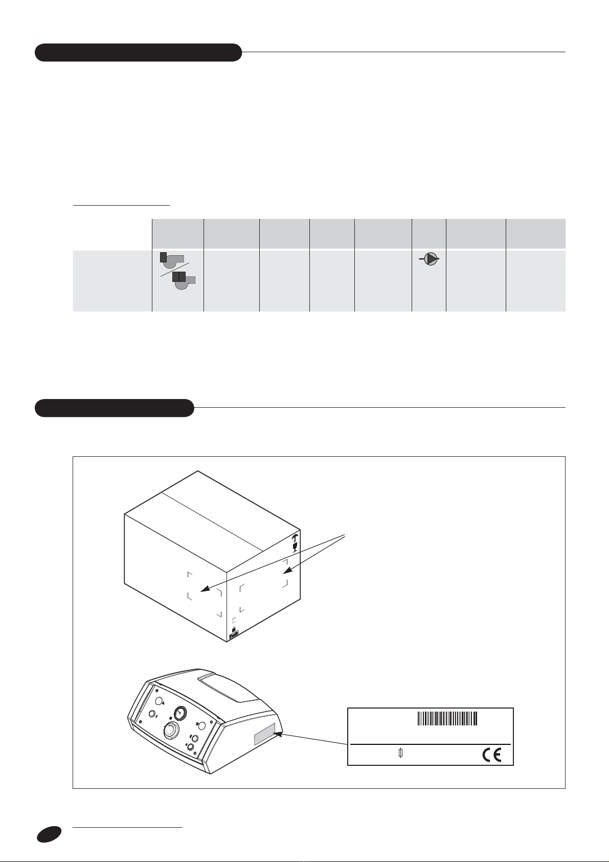
Check that the product is complete and undamaged as
soon as you remove it from its packaging. Contact the
reseller from whom you purchased the product if you noti-
ce any problems.
b
This product must be installed by a legally qualified hea-
ting engineer. (In Italy heating engineers are regulated by
law 37 of the 22/01/2008.) On completion of the installa-
tion, the installer must issue the owner with a declaration
of conformity confirming that the installation has been
completed to the highest standards in compliance with the
instructions provided by RIELLO in this instruction manual,
and that it conforms to all applicable laws and standards.
b
This control panel is designed and made for use with boi-
lers generating hot water up to 110°C, and must be used
exclusively for this purpose and within its specified perfor-
mance limits.
b
The manufacturer declines all responsibility, contractual
or other, for damage to property or injury to persons or
animals caused by improper installation, adjustment,
maintenance or use.
b
This instruction manual is an integral part of the product.
It must be kept safe and must ALWAYS accompany the
product, even if it is sold to another owner or transferred
to another user or to another installation.
If you damage or lose this manual, order a replacement
immediately from your local Technical Assistance Centre.
GENERAL SAFETY INFORMATION
PRECAUTIONS
a
Always turn the electrical power supply OFF at the main
switch before commencing any cleaning or maintenance.
a
Do not tamper with or adjust the safety or control devices
without prior authorisation and instructions from the boi-
ler’s manufacturer.
a
Never pull, disconnect, or twist the electrical cables
coming from the appliance even if it is disconnected from
the mains electricity supply.
a
Dispose of packaging materials in compliance with appli-
cable standards and legislation governing the disposal of
urban, domestic and industrial waste.
a
Never switch the control panel on even for a short period
if the safety devices are not functioning correctly or have
been tampered with.
a
All maintenance and repairs must be carried out by a
legally qualified heating engineer.
a
Do not use water to extinguish fire in the control panel.
Switch power OFF at the mains power switch to isolate
the control panel electrically first. Then use a class E fire
extinguisher (marked “SUITABLE FOR LIVE ELECTRICAL
ITEMS”) to extinguish the flames.

6
RIELLOtech PRIME control panels are thermostatic con-
trol panels for use with dedicated central heating boilers
equipped with single stage jet burners.
All thermostatic control devices comply with applicable
technical and safety standards, and are housed in an
ABS box.
All the electrical control and safety devices in RIELLOtech
PRIME control panels are factory tested in compliance
with applicable technical standards. Control panels may
be installed on top of the boiler or on one of its side
panels, using the optional side panel mounting kit.
PRODUCT DESCRIPTION
RIELLOtech PRIME control panels are identified by:
TABLEAU DE CONTROLE
CONTROL PANEL
PAN NELLO DI CONTROLLO SCHALTTA FEL CUADRO DE MANDO
20Kgmax
–
–
l'Etichetta Caratteristiche Tecniche
il N° di codice riportato sull'imballo
Cod. : 20010820
Made in Italy
Mod. : RIELLO TECH PRIME
20011290_E1
230 V AC - 50 Hz - 6.3 (A) T
20
40
60
80
100
0120
IDENTIFICATION
b To make the electrical connections to the various system components and to the burner, refer to the instructions on
page 12 and to the specific instructions supplied with each item and with the burner.
APPLICATION CHART
Burner Cascaded
boilers
Cascaded
boilers
Solar water
heating
systems
DHW storage
cylinders
Direct
zone
1st mixed
zone
2nd mixed
zone
RIELLOtech
PRIME
1
2 1
2-stage
with kit
- the code number on the box
- the technical data label

7
TECHNICAL SPECIFICATIONS
ACCESSORIES
Description
RIELLOtech PRIME
Power supply 230 (+/-10%) ~ 50 V ~ Hz
Maximum current draw 6,3 A
Main power switch (two pole) 250 ~ 10(4) V ~ A
Fuse 250 ~ 6,3 T V ~ A
Power consumption -W
Function indicators 230 V
Manual reset safety thermostat (TS) (*) 110 (+0/-6) °C
Control thermostat (TR) field of adjustment 30 ÷ 82 (+/-3)
°C
Minimum temperature thermostat (Tm)
control range 30 ÷ 90 (+/-3)
°C
working setting 40
°C
Boiler temperature gauge (TeC) 0 ÷ 120
°C
Index of protection X4D IP
Cable length 3m
(*) Homologated
The following accessories are available, to be ordered separately:
ACCESSORY CODE
Two-stage burner control kit 4031067
Wall mounting kit 20010056

8
UNPACKING THE PRODUCT
DIMENSIONS AND WEIGHT
RIELLOtech PRIME control panels come in a cardboard
box that also contains the instruction manual.
TABLEAU DE CONTROLE
CONTROL PANEL
PAN NELLO DI CONTROLLO SCHALTTA FEL CUADRO DE MANDO
20Kgmax
BA
D
C
G
E
F
H
20
40
60
80
100
0120
Description
A348 mm
B353 mm
C160 mm
D170 mm
E
236
mm
F
75
mm
G
208
mm
H
218
mm
Weight
2,7
kg

9
311
170
41
218
208
75
Lato SUPERIORE della CALDAIA
Lato ANTERIORE della CALDAIA
Lato SUPERIORE della CALDAIA
Lato FRONTALE della CALDAIA Lato FRONTALE della CALDAIA
Pannellatura LATERALE
Pannellatura SUPERIORE
Lato ANTERIORE della CALDAIALATERALE della CALDAIA
LATERALE della CALDAIA
RIELLOtech PRIME control panels can be installed either on the top of the boiler or on one of its side panels. Before
commencing installation, check the arrangement of the holes on the top panel or side panel of the boiler.
Once you have identified the right holes for the type of installation required, proceed as follows:
- Push out the pre-formed slots on the boiler casing corresponding to the oval cable grommets in the control panel
- Perforate the membranes of the control panel cable grommets. Pull out the thermostat cable and route it through the
slot in the top panel
- Secure the control panel to the boiler casing.
ASSEMBLY
TOP of boiler
FRONT of boilerSIDE of boiler
SIDE panels
TOP panels
FRONT of boiler FRONT of boiler
TOP of boiler

10
to sensor socket
in boiler
to sensor socket
in boiler
FRONT OF BOILER
FRONT OF BOILER
HORIZONTAL installation
20
40
60
80
100
0120
20
40
60
80
100
0120
Before you can install the control panel on a boiler side panel, proceed as follows:
- Remove the 4 screws (A).
- Remove the front trim (B), turn it through 180°, and fit it back on the body of the control panel (C).
- Install the control panel as instructed above.
VERTICAL installation
to sensor socket
in boiler
C
B
A
A
20
40
60
80
100
0120
20
40
60
80
100
0120
20
40
60
80
100
0120
A dedicated wall mounting kit is available. Refer to the instructions provided with the kit for details on installation.

11
b
Carefully unwind the thermostat cables and route them
through the relevant grommets. Insert the thermostat
sensors in the corresponding sockets in the boiler. Fix the
sensors securely in place. Use the cable straps provided
to secure the sensor cables.
Spring clip
Cable
Sensor
r
Radius ≥20 mm
Sensor socket
Only personnel from Riello’s Technical Assistance Service
or professionally qualified heating engineers are allowed
to access components inside the control panel.
Proceed as follows if you need to access components
inside the control panel:
- Turn the system OFF at the mains power switch
- Remove the top panel (1) by pulling it outwards.
1
ACCESSING INTERNAL COMPONENTS

12
b The following instructions are mandatory:
1 - Use a single pole magnetic thermal trip switch
and disconnector conforming to IEC-EN stan-
dards (with a contact gap of at least 3 mm);
2 - Respect the L (Phase) - N (Neutral) polarity.
Keep the ground wire about 2 cm longer than the
power wires.
3 - Use cables with a cross section of 1.5 mm2or
more, complete with end terminals;
4 -
Always refer to the electrical wiring diagrams in
this manual when performing any electrical work.
5 -Make sure the appliance is connected to an
effective ground.
- Proceed as instructed in the “ACCESSING INTERNAL
COMPONENTS” section above to access the terminals
inside the control panel.
- Route the connection cables through the cable grom-
mets in the casing of the boiler or secured by the side
mounting bracket. Alternatively, use the holes provided
for cable glands or spiral sleeving. To use these holes,
push out the pre-formed hole covers in the correspon-
ding positions on the control panel.
- See the “WIRING DIAGRAMS” section for information
on how to connect up the individual devices.
- Tighten the screws on the cable clamps and screw up
the cable glands to secure the cables against pulling.
Secure the cables to the casing of the boiler as neces-
sary.
b
Use the terminals provided to connect all 230 V
power users to ground.
a
It is strictly forbidden to use gas and/or water pipes
to ground the appliance.
a
Do not route the power cable or room thermostat
cables near hot surfaces (like heating circuit flow
pipes). Use a suitable class of cable if there is any
possibility of contact with parts at temperatures
above 50°C.
The manufacturer declines all responsibility for dama-
ge caused by failing to ground the appliance adequa-
tely or by failure to respect the wiring diagrams pro-
vided in this manual.
All electrical connections must be made by a legally qualified heating engineer according to the following instructions.
(In Italy heating engineers are regulated by law 37 of the 22/01/2008.)
ELECTRICAL CONNECTIONS
L1 N PE
BURNER CH PUMP
T1 T2 S3 L1 N PE1
Power supply
PENL
TA
Cable glands
“A”
Boiler
temperature
gauge sensor
Minimum
temperature
thermostat
sensor
Tm
Control
thermostat
sensor Safety
thermostat
sensor
Cable glands
“B”
TR
TS
TeC

13
POSITIONING THE SENSORS
TeC TR TS
Tm
TA
AE
RI MI
PI
RIELLOtech PRIME
Caldaia
20
40
60
80
100
0120
Tm - Minimum temperature thermostat
sensor
TS - Safety thermostat sensor
TR - Control thermostat sensor
TeC - Boiler temperature gauge sensor
TA - Room thermostat
AE - 230V~50Hz electrical power supply
MI - CH flow
RI - CH return
PI - CH pump
b Refer to the manual supplied with the boiler to identify the sensor sockets correctly.
b Insert the thermostat sensors in the corresponding sockets and fix them securely in place. Use the
cable straps provided to secure the sensor cables.
Boiler

14
MO1-1
MO1-2
MO1-4
MO2-8
MO1-5
MO2-7
MO1-3
TR 30-82°C
Tm
30-90/R40°C
TS 110°C
H2 H1
L1
N
PE
PI
MO2-9
KA1
IP
IP
BA1
L1
T2
N
PE
S3
T1
B4
BR
MO2-1
MO2-4
MO2-5
MO2-6
MO2-2 MO2-3
TA
FU
WIRING DIAGRAMS
L1-N-PE 230V~50Hz power supply
FU Fuse 6.3 A-T
IP Main switch
TS Manual reset safety thermostat (110°C)
TR Control thermostat (30-82°C)
Tm Minimum temperature thermostat (30-90/R40°C)
KA1 Relay contacts
BA1 Relay coil
BR Burner
H1 Burner lockout indicator
H2 Overtemperature indicator
Connections to be made by the installer:
TA Room thermostat
PI CH pump

15
11 10 8
231 6 754
9
20
40
60
80
100
0120
1 - Overtemperature indicator
2 - Manual reset safety thermostat (110°C)
3 - Control thermostat (30-82°C)
4 - Boiler temperature gauge
5 - Fuse
6 - Burner lockout indicator
7 - Two pole ON/OFF switch
8 - Minimum temperature thermostat sensor (Tm) (accessible from inside)
9 - Safety thermostat sensor (TS)
10 - Control thermostat sensor (TR)
11- Boiler temperature gauge sensor (TeC)
LAYOUT
b
The cables for the TS, TR, TeC and Tm sensors must be routed out of the electric control panel
and through the cable grommets in the boiler during installation.

16
DESCRIPTION OF FUNCTIONS
Main control panel ON/OFF switch (b)
This switch connects power to all controlled devices and
appliances.
b
A delayed action 6.3 A fuse is installed inside the control
panel upstream from this switch (see wiring diagram).
Control thermostat (
r
)
The control thermostat lets you adjust boiler temperatu-
re between 60 and 82°C The recommended setting is
around 70°C.
Safety thermostat (TS)
The safety thermostat shuts down the burner if boiler
temperature exceeds 110°C.
To restore normal functioning, remove the protective
cover and press the button . Use a suitable tool if
necessary.
b
If the safety thermostat (TS) shuts down the burner,
the red warning light comes on and any burner
error signals on the burner controller are lost.
Minimum temperature thermostat (Tm)
This thermostat prevents cold water from circulating and
causing condensation inside the boiler. It is located insi-
de the control panel, and is preset to 40°C. Adjustment
requires a suitable tool and is reserved for personnel from
r’s Technical Assistance Service.
RIELLOtech PRIME control panels are equipped with 3 homologated electromechanical thermostats, a temperature
gauge, a main power ON/OFF switch, function indicators and a protective fuse.
20
40
60
80
100
0120
20 100
0120
20
40
60
80
100
0120

17
SELLER:
Mr. ......................................................................................................................................................
Address...........................................................................................................................................
tel. ......................................................................................................................................................
TECHNICAL ASSISTANCE SERVICE:
Mr. ......................................................................................................................................................
Address...........................................................................................................................................
tel. ......................................................................................................................................................
BOILER DETAILS
(From Data label):
Make ..................................................................................................................................................
Type ...................................................................................................................................................
Serial number ........................................................................................................................
Date of initial start-up ...............................................................................................
INSTALLER:
Mr. ......................................................................................................................................................
Address...........................................................................................................................................
tel. ......................................................................................................................................................
CONTROL PANEL DETAILS
(From product label):
Serial number ........................................................................................................................
Lot ......................................................................................................................................................
.........................................................................................................................................................................................................................................................................................................................................................
.........................................................................................................................................................................................................................................................................................................................................................
.........................................................................................................................................................................................................................................................................................................................................................
.........................................................................................................................................................................................................................................................................................................................................................
.........................................................................................................................................................................................................................................................................................................................................................
.........................................................................................................................................................................................................................................................................................................................................................
.........................................................................................................................................................................................................................................................................................................................................................
.........................................................................................................................................................................................................................................................................................................................................................
.........................................................................................................................................................................................................................................................................................................................................................
USEFUL INFORMATION

18


RIELLO S.p.A. - 37045 Legnago (VR)
Tel. 0442630111 - Fax 044222378 - www.riello.it
The manufacturer strives to continuously improve all products. Appearance, dimensions, technical specifications,
standard equipment and accessories are therefore liable to modification without notice.
Cod. 20020611
Instructions for the correct disposal of the product
pursuant to European Directive 2002/96/EC
At the end of its working life, the product cannot be disposed of as municipal
waste. It can be delivered to separate waste collection centres operated by
local councils, if such exist, or to the resellers that provide this service.
Separate disposal of appliances avoids possible negative consequences for
the environment and the health due to unsuitable disposal and
allows the recovery of the components, with significant savings in
terms of energy and resources. The symbol (crossed-out wheeled
bin) shown on the product indicates that the appliance must be
disposed of separately.
This manual suits for next models
1
Table of contents
Other Riello Control Panel manuals

Riello
Riello Thermital TBOX BASIC ACS Technical manual

Riello
Riello RIELLOtech CLIMA TOP 4031065 User manual

Riello
Riello CPD 35 User manual

Riello
Riello Wired Touch panel User manual

Riello
Riello CBD 35 User manual

Riello
Riello 4030011 User manual

Riello
Riello CBD 25 User manual

Riello
Riello 20081467 User manual

Riello
Riello CBD 20 PLUS User manual

Riello
Riello CPD 30 User manual