manuals.online logo
Brands
  1. Home
  2. •
  3. Brands
  4. •
  5. Rielta
  6. •
  7. Security Sensor
  8. •
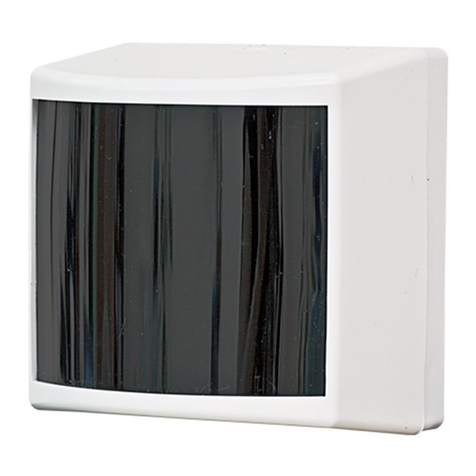
  9. Rielta FOTON-SH2 User manual

Rielta FOTON-SH2 User manual

Figure 4
Figure 3
PASSIVE INFRARED
DETECTOR
«FOTON-SH2»
Installation Guide Figure1
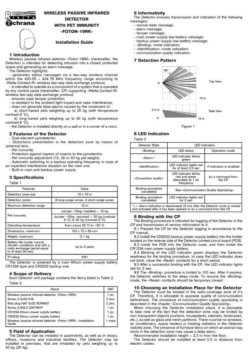
7 Detection Zone Pattern
1 General Information
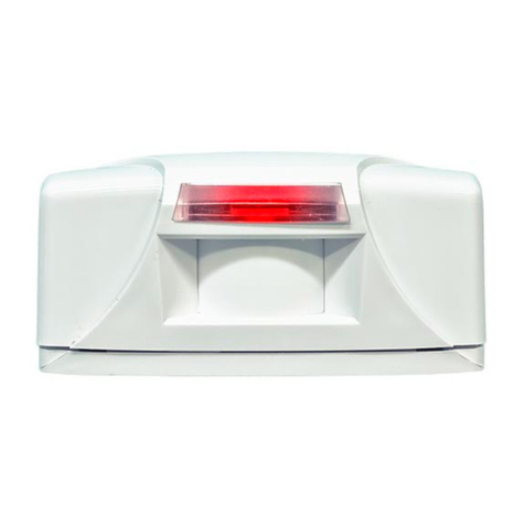
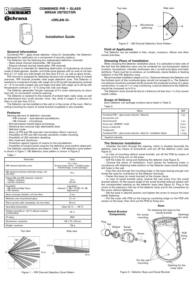
Passive infrared detector «Foton-SH2» (hereinafter, the Detector)
is intended for detecting intrusion into a protected premises through
door or window openings and generating an alarm message by output
relay contacts opening. The Detector generates «Sabotage» message
by microswitch contacts opening.
The Detector has immunity to interference caused by small animals
and ambient light.
2 Features of the Detector
- Dual-element pyrodetector.
- «Vertical curtain» detection zone.
- Microprocessor-based signal processing.
- Temperature compensation of the detection sensitivity.
- The maximum Detector installation height is up to 5 m.
- Possibility of LED indication disabling.
- Two-way installation using four fastening surfaces of the Detector
base: either above the protected opening, or in the corners of window
openings, door cases, etc.
- High resistance to ambient light – 12000 lx.
- Immunity to electromagnetic interference.
- Case tamper protection.
- High immunity to the ambient light (up to 12 000 lx).
- High immunity to electromagnetic interferences.
- Tamper protection.
3 Specifications
Table1
Parameter Value
Voltage supply 9 … 15 V DC
Alarm message duration 3 sec
Consumption current, мах 10 mA
Detection zone type Vertical curtain
Operating temperature minus 30 оС ... +55 оС
Relative humidity at +25 оС without moisture
condensation up to 98 %
Dimensions, maximum 80 х 47 х 40 mm
Weight, not more than 60 g
IP rating IP41
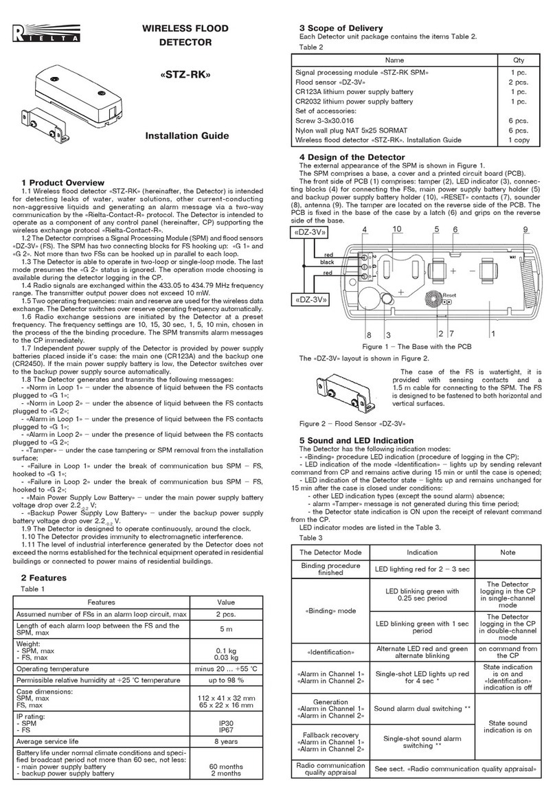
4 Scope of Delivery
Each Detector unit package contains the items listed in Table 2.
Table 2
Name QNT
Passive infrared detector «Foton-SH2»
Screw nail 3-3х30.016
Passive infrared detector «Foton-SH2». Installation Guide
1 pc.
2 pcs.
1 copy
5 LED Indication
LED indicator is used for the Detector status displaying. For LED
indication disabling remove jumper IND. Set the jumper on one of the
male pins for the further usage during testing.
Table 3
Message LED indicator Duration
«Warm-up time» ON Maximum 60 sec
«Norm» OFF -
«Alarm» ON 3 sec
«Failure» Blinking at 1 Hz
frequency
10 sec after failure
cause elimination
6 Choosing Place of Installation
When choosing locations for the Detector installation, it is advisable
to take note of the fact that the detection zone may be limited by
non-transparent objects (curtains, curtain holders, door trims, etc),
as well as glass partitions. There must be no air conditioners, space
heaters or heating radiators in the Detectors’ detection zone.
Maximum installation height of the Detector is 5 m. Alarm loops should
be wired far enough from power supply cables. Variants of installation
are shown in Figure 1.
8 m
6 m
Till 5 m
5 m
a)
60
110
b)
10 m
900
Figure 2
8 Installation
- Remove the Detector cover by pressing on the back wall of the
Detector base (Figure 3) and pressing the edges of the cover by the
fingers of the other hands at the points shown in Figure 4, put off the
cover.
- Insert a screwdriver with a flat drive blade between the printed
circuit board (PCB) and the back wall of the base, depress the base
wall and remove the PCB (Figure 5).
- Depending on the chosen location of the Detector, determine the
Detector base sides for fastening to the installation place and drill
fastening holes or press them out with a screwdriver (Figure 6).
Figure 5 Figure 6
- Insert wires through the openings for wiring. Leave several
centimeters of the wire for plugging to the terminal boards.
- Fasten the base on the chosen place.
- Install the PCB in the base and latch it on both sides.
- Fulfill connections in accordance with Figure 7.
+12V-
To the CP
loops
Power
supply
AL
To the CP
loops
TAMPER
Figure 7
- Reinstall the Detector cover by engaging it over the latch on the
front wall of the base (Figure 8) and latch the cover onto the base.
Figure 8
9 Functional Testing
Detection zone alignment (see Figure 2) should be checked as
follows:
- set jumper IND (LED is ON);
- energize the Detector and wait for 1 minute;
- start walking through the detection zone at a speed rate
0.5 –1 m/sec. When two zone lines are crossed, the Detector transmits
an alarm message (LED indicator switches ON and the relay contacts
open);
- cross the detection zone on the other side and define it’s other
border. When there is no motion in the detection zone, alarm messages
should not be generated.
In case the detection zone is screened by some objects (curtain
holders, curtains, door trims), then position of the Detector should
be changed.
If additional alignment of the detection zone is needed, you may
use a universal swivel bracket (available optionally).
After retesting install the IND jumper to the required mode position
depending on protection tactics.
10 Self-Test Mode
The Detector provides self-testing automatically. During this mode
input voltage and ambient temperature values are checked.
In temperature range near to 36 °С (human body temperature), the
sensitivity threshold shift takes place, resulting in detectability level
increase.
In case of voltage drop lower than 9-1 V, «Failure» message is
generated by opening the relay output contacts repeated by periodical
LED indicator blinking during failure and 10 sec after it’s elimination.
ATTENTION! The Detector must be checked at least annually in
order to test their performance.
11 Storage and Transportation
The Detectors in their original packing may be shipped by any
transport means in covered vehicles (in railway, cars, trucks, sealed
heated compartments of aircraft, ship cargo holds, etc). The storage
room should be free from current-conducting dust, acid vapors, alkali
and gases that cause corrosion and destroy insulation.
The Detectors in their original packing may be stored not more than
3 months. During this period the Detector package should not have
bloodshot spots and impurities.
Upon the expiry of 3 months, the Detector should be released from
the package.
12 Manufacturer’s Guarantees
The Manufacturer guarantees conformity of the Detector to it’s
Technical Specifications if conditions of transportation, storage,
assembling and operation are observed. The guaranteed storage
period is 63 months since the date of manufacturing the Detector.
The guaranteed period of operation is 60 months since the date of
commissioning within the storage period guaranteed.
The Detectors that are found to non-conforming to it’s Technical
Requirements shall be repaired by the Manufacturer, provided the
installation and operation rules have been complied with.
13 Packing Certificate
Passive infrared detector «Foton-SH2» has been manufactured in
compliance with the active technical documentation and classified as
fit for operation and packed by «RIELTA» JSC.
Packing date _______________________________
month, year
«RIELTA» JSC, www.rielta.com,
Chapaeva Str. 17, Saint Petersburg, Russia, 197101, [email protected],
Tel./fax. +7 (812) 233-0302, 703-1360,
Technical support, tel. +7 (812) 233-29-53, 703-13-57, [email protected].
Made in Russia
Rev. 4, 10 of 13.09.19
v.2

Other Rielta Security Sensor manuals

Rielta Ladoga MK-RK User manual

Rielta

Rielta Ladoga MK-RK User manual

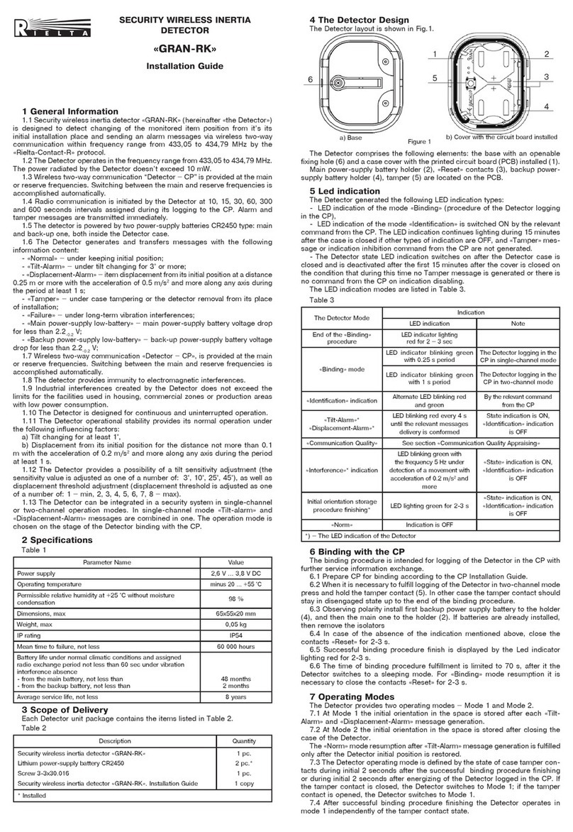
Rielta FOTON-SH2-RK User manual

Rielta

Rielta FOTON-SH2-RK User manual

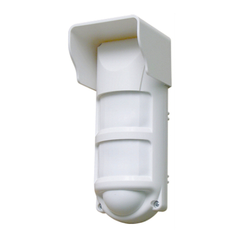
Rielta PYRONE-8-RK User manual

Rielta

Rielta PYRONE-8-RK User manual

Rielta STZ-RK User manual

Rielta

Rielta STZ-RK User manual

Rielta chrana ORLAN-SH User manual

Rielta

Rielta chrana ORLAN-SH User manual

Rielta FOTON-SH1 User manual

Rielta

Rielta FOTON-SH1 User manual

Rielta STZ-RK User manual

Rielta

Rielta STZ-RK User manual

Rielta FOTON-21 User manual

Rielta

Rielta FOTON-21 User manual

Rielta GRAN-RK User manual

Rielta

Rielta GRAN-RK User manual

Rielta Ladoga MK-RK User manual

Rielta

Rielta Ladoga MK-RK User manual

Rielta CELSIUS-RK User manual

Rielta

Rielta CELSIUS-RK User manual

Rielta C.Nord CN-PIR User manual

Rielta

Rielta C.Nord CN-PIR User manual

Rielta ZVON-1 User manual

Rielta

Rielta ZVON-1 User manual

Rielta ZVON-1 User manual

Rielta

Rielta ZVON-1 User manual

Rielta GRAN-RK User manual

Rielta

Rielta GRAN-RK User manual

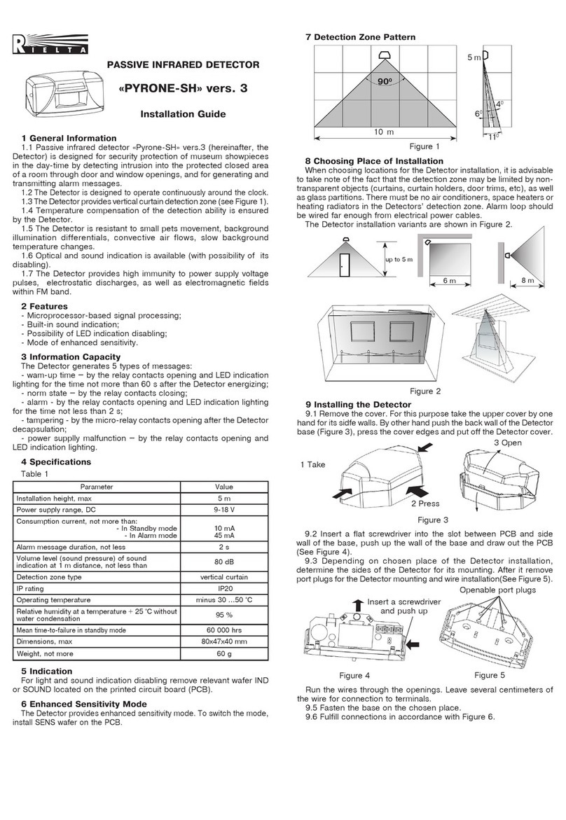
Rielta PYRONE-SH2-RK User manual

Rielta

Rielta PYRONE-SH2-RK User manual

Rielta PYRONE-SH2-RK User manual

Rielta

Rielta PYRONE-SH2-RK User manual

Rielta Pyrone-4D User manual

Rielta

Rielta Pyrone-4D User manual

Rielta UDAR User manual

Rielta

Rielta UDAR User manual

Rielta STEKLO-3RK User manual

Rielta

Rielta STEKLO-3RK User manual

Rielta STZ-RK User manual

Rielta

Rielta STZ-RK User manual

Rielta Ladoga MK-RK version 2 User manual

Rielta

Rielta Ladoga MK-RK version 2 User manual

Rielta FOTON-15B User manual

Rielta

Rielta FOTON-15B User manual

Rielta ORLAN-D User manual

Rielta

Rielta ORLAN-D User manual

Popular Security Sensor manuals by other brands

Feig Electronic VEK MNH1-R24-A quick start guide

Feig Electronic

Feig Electronic VEK MNH1-R24-A quick start guide

Crow GENIUS Installation instructions and instructions for use

Crow

Crow GENIUS Installation instructions and instructions for use

hager TRC301B quick start guide

hager

hager TRC301B quick start guide

Optex SL-100 TNR installation instructions

Optex

Optex SL-100 TNR installation instructions

Dormakaba M A01 quick start guide

Dormakaba

Dormakaba M A01 quick start guide

aquilar AquiTron AT-G-ALERT-C Installation and operation instructions

aquilar

aquilar AquiTron AT-G-ALERT-C Installation and operation instructions

Velleman PIR1200C user manual

Velleman

Velleman PIR1200C user manual

Honeywell EC-P2 instruction manual

Honeywell

Honeywell EC-P2 instruction manual

Pepperl+Fuchs WILSEN.sonic.level WS-UCC4000 manual

Pepperl+Fuchs

Pepperl+Fuchs WILSEN.sonic.level WS-UCC4000 manual

Hilti PS 200 S manual

Hilti

Hilti PS 200 S manual

Riels UAL358 manual

Riels

Riels UAL358 manual

Kistler 8852A Series instruction manual

Kistler

Kistler 8852A Series instruction manual

PCB Piezotronics 108B01 Installation and operating manual

PCB Piezotronics

PCB Piezotronics 108B01 Installation and operating manual

ABB Busch-Wachter Presents 6131-74-101-500 user manual

ABB

ABB Busch-Wachter Presents 6131-74-101-500 user manual

Challenger AD04N quick start guide

Challenger

Challenger AD04N quick start guide

Design Light WYL-CR-M3-BI-01 Assembly instruction

Design Light

Design Light WYL-CR-M3-BI-01 Assembly instruction

Elmes Electronic CTX3H quick start guide

Elmes Electronic

Elmes Electronic CTX3H quick start guide

Clas Ohlson SH98RF quick start guide

Clas Ohlson

Clas Ohlson SH98RF quick start guide

manuals.online logo
manuals.online logoBrands
  • About & Mission
  • Contact us
  • Privacy Policy
  • Terms and Conditions

Copyright 2025 Manuals.Online. All Rights Reserved.