manuals.online logo
Brands
  1. Home
  2. •
  3. Brands
  4. •
  5. Rielta
  6. •
  7. Security Sensor
  8. •
  9. Rielta FOTON-21 User manual

Rielta FOTON-21 User manual

1 General Information
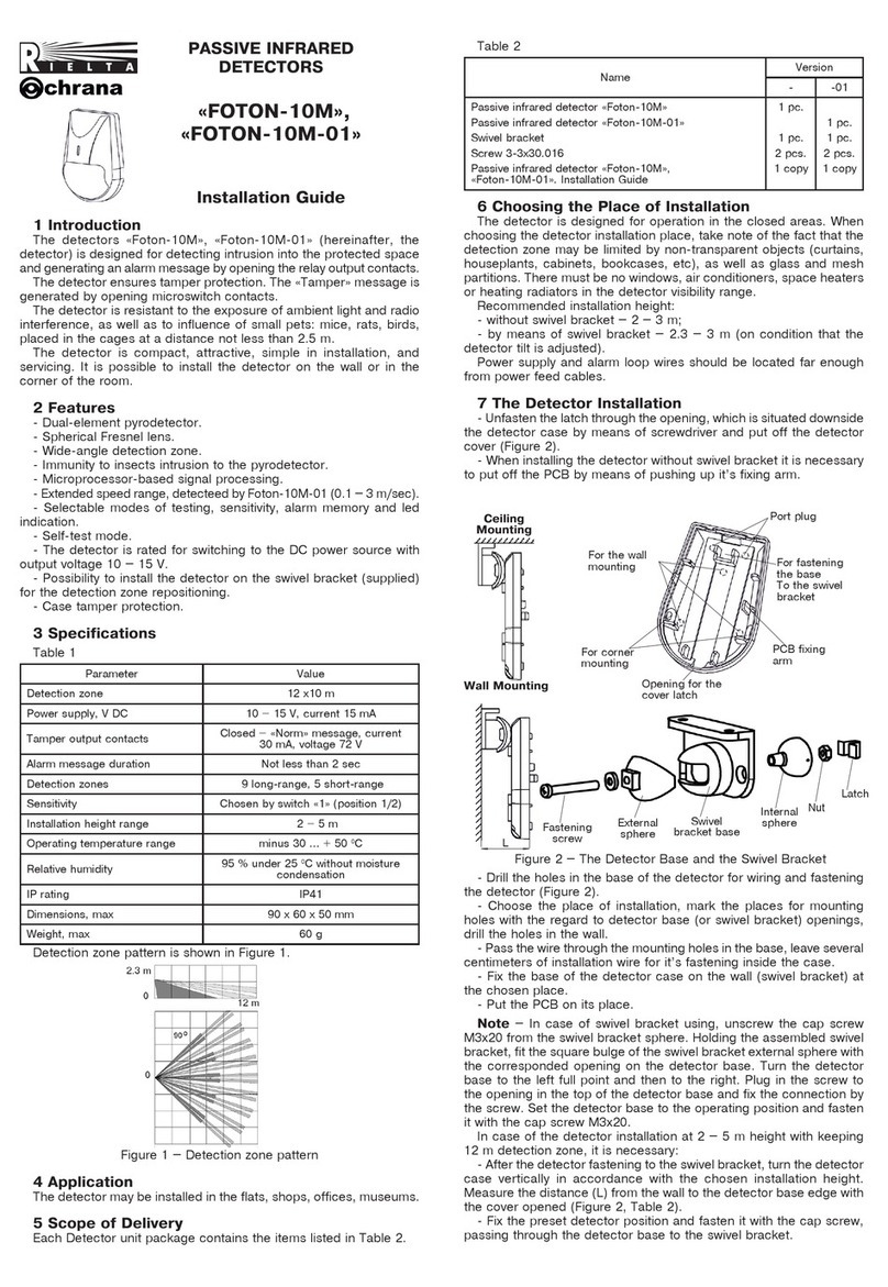
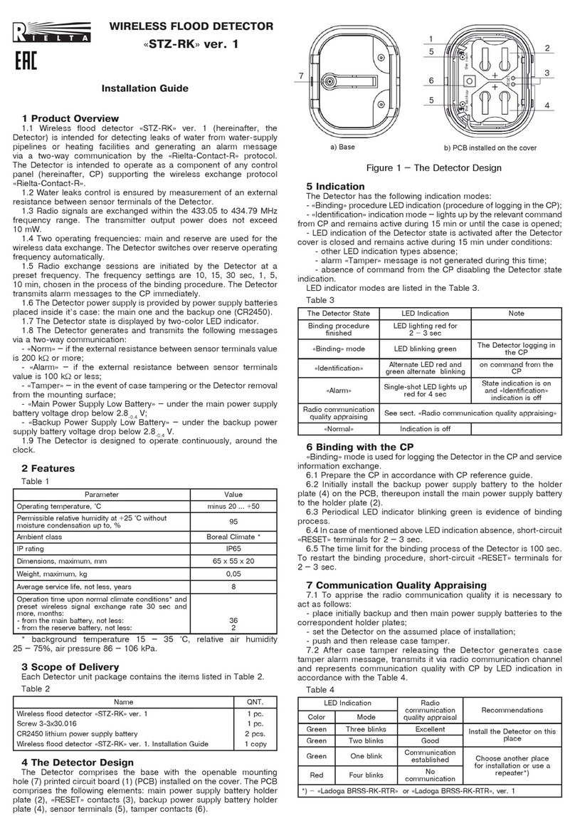
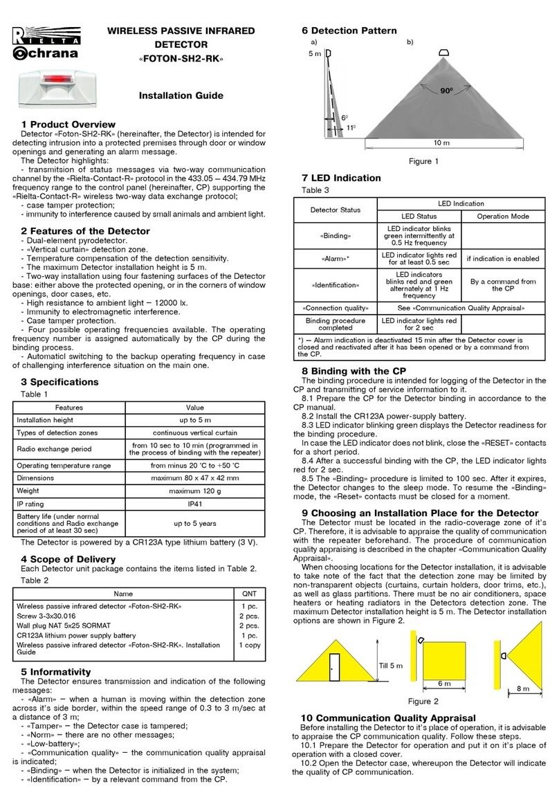
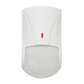
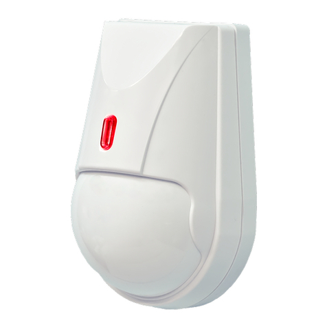
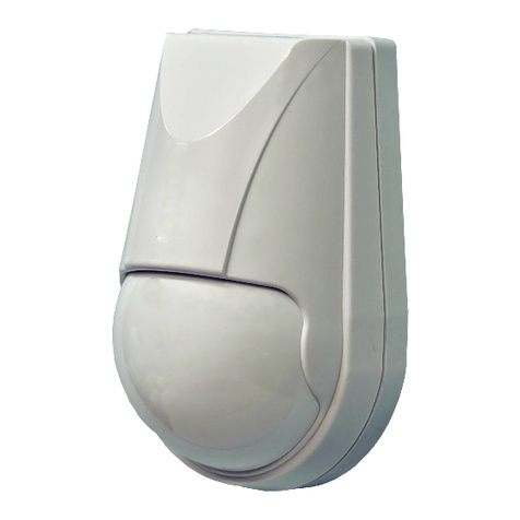
Passive infrared detector «Foton-21» (hereinafter, the Detector) is intended
for detecting intrusion into a closed protected space and generating an alarm
message by relay output contacts opening.
The Detector ensures tamper protection by means of «Tamper» microswitch
relay contacts opening.
The Detector is resistant to the ambient light impact and radio interference.
The Detector ensures absence of false alarms cased by movement of small
animals: mice, rats, birds in cages at a distance to them not less than 2.5 m.
The Detector is distinct in: attractive design, ease of installation and
maintenance.
2 Features
- The Detector is designed for ceiling mounting.
- Sensing elements – two dual-element pyrodetectors.
- Digital temperature compensation.
- Unique lens provides wide-range detection zone with high filled density,
ensuring reliable detection of the intrusion in any direction.
- Protection against intrusion of insects to a pyrodetector.
- Microprocessor-based signal processing.
- Choosing of installation height as well as the following modes: testing, alarm
memory, and LED indication.
- Self-test mode ensuranse.
- The Detector is supplied from DС current supply unit with output voltage
(9 … 15) V.
3 Specifications
Table 1
Parameter Value
Detection zone diameter at mounting height:
5 m, not less than
2.5 m, not less than
9 m
4.5 m
Power supply 9...15 V DC, current 17 mА
Output relay contacts Energized Form A (NC) relay, max.
current 30 mА, voltage 72 V
Alarm message duration, not less than 2 sec
Detection zone
Wide-angle, cone-shaped.
Zones: 10 long-range, 1 middle-range,
1 short-range
Detection range at the installation height
5 m and 2.5 m
Is chosen by «1» DIP-switch
Operating temperature minus 40 ... +50 °С
Relative humidity at 25 °С without moisture
condensation 95 %
IP Rating IP41
Dimensions (diameter х height), not more than 105 х 45 mm
Weight, not more than 100 g
Detection zone pattern is shown in Figure 1.
PASSIVE INFRARED
DETECTOR
«FOTON-21»
Installation Guide
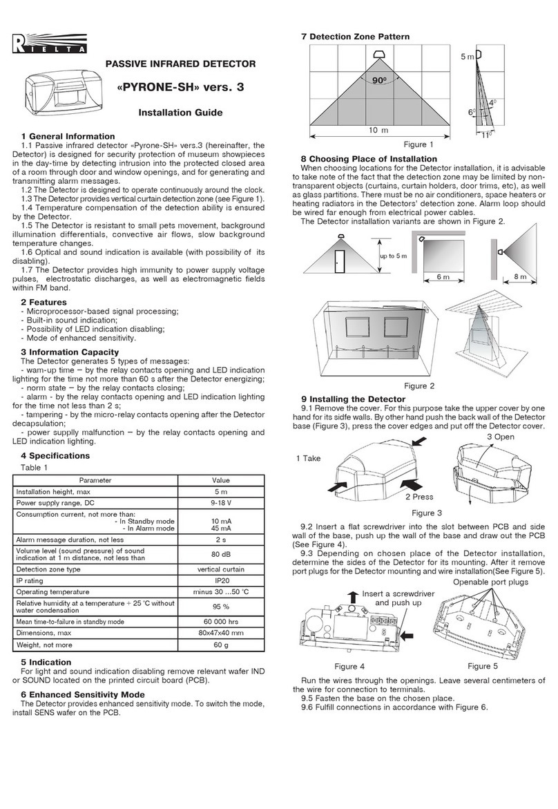
When choosing the Detector installation place, it is advisable to take note
of the fact that the detection zone may be limited by non-transparent objects
(curtains, houseplants, cabinets, bookcases, etc.), as well as by glass and mesh
partitions. There must be no windows, air conditioners, space heaters or heating
radiators in the PIR-detection zone.
The Detector wires should be laid far enough from power supply cables.
7 Installation of the Detector
- Put off the Detector cover by it’s turning counter-clockwise until tight to the
recess on the external ring of the Detector base and then rise the cover (Figure 2).
Figure 2 – Base and cover of the Detector
- Put off the printed circuit board (PCB) by unfastening the latch, located
on the base.
- Drill the holes in the base (See Figure 3) for the Detector wiring and
fastening the base.
- Choose the place of installation, mark the places for mounting holes with
regard to the openings on the Detector base, drill holes in the place of installation.
- Insert wires into the hole in the base leaving several centimeters for fixation
inside the case and connection to the leading-in sockets.
- Fix the base of the detector on the chosen place.
- Set down PCB on their places.
8 Connection
- Leading-in sockets for the Detector connection are located on the PCB.
- Fulfill connections in accordance with Figure 3а (for hooking up to single
AL) or Figure 3b (to single tamper control AL).
- Set up the DIP-switches «1», «2», «3», «4» in accordance with particular
application conditions and Cl.9 of herein Installation Guide.
- Install the Detector cover on it’s place. For this purpose insert the bulge
to the recess on the base external ring, push the cover and turn it in clockwise
Bulge
Base Cover
Recess
Openable holes for the
base fastening Port plugs for wiring
Latch
Figure 1 – Detection zone pattern
Ambient class: Boreal Climate (background temperature 15 – 35 оС, relative
humidity 25 – 75 %, air-pressure 86 – 106 kPa), permissible relative humidity
at +25 °С without moisture condensation.
4 Scope of Delivery
Each Detector unit package contains the items listed in Table 2.
Table 2
Name QNT.
Passive infrared detector «Foton-21»
Passive infrared detector «Foton-21». Installation Guide
1 pc.
1 copy
5 Field of Application
The Detector can be applied in flats, shops, offices, museums, industrial
facilities.
6 Choosing the Installation Place
The Detector is designed for operation in heated closed premises.
Figure 3
9 DIP-switches Positions
Table 2
Mode DIP-switch DIP-switch position
ON OFF
Installation height «1» «5 m» «2.5 m»
Detection zone
testing (sizing) «2» «ZONE»
Testing
«ALARM»
Normal operation
Alarm indication «3» «IND»
is ON
«OFF»
is OFF
Alarm memory «4» «MEM»
is ON
«OFF»
is disabled
10 LED Indication
Two-color LEDs on the front cover are used for the Detector state displaying.
Table 3
Message LED Color LED State
«Warm-up time» red Blinking at a frequency 1 Hz during 55 sec after
energizing
«Norm» - Indication is OFF
«Alarm» red
Indication is ON during 3 sec
«Failure»
green Single three-shot switching with a period of
3 sec in accordance with Cl. 15
«Alarm Memory» green LED indication is ON in 5 min.after «Alarm»
message for 15 min
Detection zone
positioning red
Switching for 0.25 sec under crossing of each
ray of the DZ. Mode duration is 5 min after
warm-up time
CircuitCont.
1
2
3
4
5
6
+12V
-12V
AL
AL
Taper
Taper
To power
source
Rterm1
To CP
а)
Taper-
control
AL
Security
AL
Rterm1
Circuit
Cont.
To power
supply unit
Rterm1
Detector
1
2
3
4
5
6
+12V
-12V
AL
AL
Taper
Taper
b)
Detector
10 m
5 m
9 m
11 The Detector Switching on and Checking
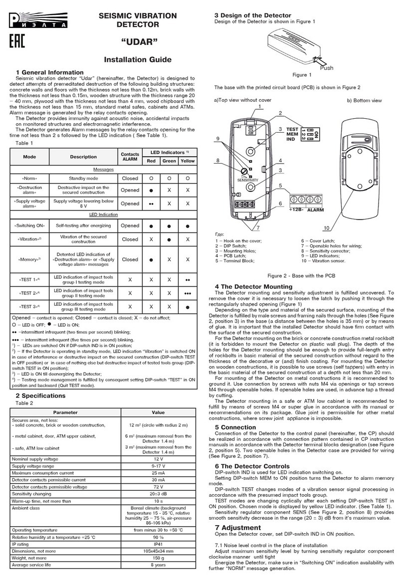
For mounting height 5 m set up DIP-switch «1» to ON position (5 m). If
the ceiling hight of the room is less than 3 m, it is recommended to set up
DIP-switch «1» to OFF position (2.5 m). Thus, the higher sensitivity level is
provided. It is recommended to use the Detector in this mode in small rooms
with severe interference conditions.
After enegizing the Detector executes self-testing (checking of power supply,
environment temperature as well as amplification path testing), the LED blinks
red (independently from DIP-switch «3» position), output contacts are opened.
During self-testing procedure it is necessary to exclude any movement in the
detection zone, asi can result in failure message generation.
12 Functional Check
Upon expity «Warm-up Time», the Detector changes to standby mode and is
able to generate an alarm message.
High filled density of the Detection zone provides to detect intruder moving
in any direction. Testing and sensitivity adjustment is fulfilled so as to determine
the detection zone borders.
Testing mode
DIP-switches position: «3» – ON, «2» – ON.
This mode ensures determination of each detection zone beam position. After
each beam crossing, the indicator switches for 0.25 sec. Optimal movement
speed at maximal distance is 0.5 m/sec.
Note – In this mode there is no LED indication of аlarm message.
Under absence of movement inside the detection zone, the indicator should
not light. The testing mode is performed during 5 min, whereafter the Detector
changes over to «Norm» mode.
Sensitivity Check
DIP switches position: «3» – ON, «2» – OFF. This mode is intended for the
Detector sensitivity appraisal (the distance inside the detection zone, which is
covered before alarm message generation). Alarm message is generated after
2 – 5 steps inside the detection zone (depending on mounting height and
direction of movement) during 3 sec.
After each alarm message generation, stop and make a pause till the LED is off,
after it wait for 8 – 10 sec before proceeding movement inside the detection zone.
Note – In the temperature range near 36 °С, temperature compensation is
switched on, providing maintainance of detection ability of the Detector.
13 LED Indicator Disabling
For the Detector operation masking, LED indicator disabling mode is provided.
DIP-switch «3» is in OFF position. In this mode LED is functioning only in first
minute of operation after the Detector energizing, as well as in modes «Alarm
memory» and «Failure».
14 Alarm memory
DIP-switch «4» is ON. The LED is lighting green in 5 min after alarm
message generation. LED indication duration is 15 min. Change-over of
DIP-switch «4» from ON to OFF position results in the «Alarm memory»indication
reset.
15 Self-testing and Failure Indication
The Detector fulfills self-testing automatically, thereby the following parameters
are checked:
- availability of the receiver and signal amplifier;
- power supply voltage;
- environment temperature.
The Detector generates «Failure» message with 15 min period under the
following conditions:
- power supply voltage drop lower than 9.0-1 V – by the relay contacts opening,
duplicated by perionical single LED indicator blinking green;
- maximal permissible temperature value exceedance – by the relay contacts
opening, duplicated by perionical twofold LED indicator blinking green;
- negative result of the receiver with signal amplifier testing – by the relay
contacts opening, duplicated by perionical threefold LED indicator blinking green.
After removal of the failure cause, the Detector turnes over to the «Standby»
mode automatically in 15 min. Premature reset of «Failure» LED indication can
be fulfilled by changing DIP-switch «2» position from ON to OFF (or vice versa).
ATTENTION! The Detector must be checked at least annually in order to
test it’s performance.
16 Storage and Transportation
16.1 The Detectors in their original packing may be shipped by any transport
means in covered vehicles (in railway, cars, trucks, sealed heated compartments
of aircraft, ship cargo holds, etc). The storage room should be free from
current-conducting dust, acid vapors, alkali and gases that cause corrosion
and destroy insulation.
16.2 The Detectors in their original packing may be stored not more than 3
months. During this period the Detector package should not have bloodshot
spots and impurities.
16.3 Upon the expiry of 3 months, the Detector should be released from
the package.
17 Manufacturer’s Guarantees
The Manufacturer guarantees conformity of the Detector to it’s Technical
Specifications if conditions of transportation, storage, assembling and operation
are observed. The guaranteed storage period is 63 months since the date of
manufacturing the Detector.
The guaranteed period of operation is 60 months since the date of
commissioning within the storage period guaranteed.
The Detectors that are found to non-conforming to it’s Technical Requirements
shall be repaired by the Manufacturer, provided the installation and operation
rules have been complied with.
18 Acceptance and Packing Certificate
Passive infrared detector «Foton-21»,
serial number ____________,
has been manufactured in compliance with the active technical documentation
and classified as fit for operation and packed by «RIELTA» JSC.
Person in charge of acceptance and packing
QC representative_________________ __________________.
day, year, month
Rev. 1 of 25.02.2015
№00117
Made in Russia
«RIELTA» JSC, www.rielta.com,
Chapaeva Str. 17, Saint Petersburg, Russia, 197101, [email protected],
Tel./fax. +7 (812) 233-0302, 703-1360,
Technical support, tel. +7 (812) 233-29-53, 703-13-57, [email protected].

Other Rielta Security Sensor manuals

Rielta PYRONE-SH2-RK User manual

Rielta

Rielta PYRONE-SH2-RK User manual

Rielta FOTON-16A User manual

Rielta

Rielta FOTON-16A User manual

Rielta FOTON-10B User manual

Rielta

Rielta FOTON-10B User manual

Rielta chrana ORLAN-SH User manual

Rielta

Rielta chrana ORLAN-SH User manual

Rielta STEKLO-3M User manual

Rielta

Rielta STEKLO-3M User manual

Rielta ORLAN-D User manual

Rielta

Rielta ORLAN-D User manual

Rielta ZVON-1 User manual

Rielta

Rielta ZVON-1 User manual

Rielta Ladoga MK-RK User manual

Rielta

Rielta Ladoga MK-RK User manual

Rielta PYRONE-SH User manual

Rielta

Rielta PYRONE-SH User manual

Rielta PYRONE-SH User manual

Rielta

Rielta PYRONE-SH User manual

Rielta IPDL-Ex User manual

Rielta

Rielta IPDL-Ex User manual

Rielta FOTON-17 User manual

Rielta

Rielta FOTON-17 User manual

Rielta STEKLO-3 User manual

Rielta

Rielta STEKLO-3 User manual

Rielta Pyrone-4D User manual

Rielta

Rielta Pyrone-4D User manual

Rielta FOTON-SH2-RK User manual

Rielta

Rielta FOTON-SH2-RK User manual

Rielta Pyrone-7i User manual

Rielta

Rielta Pyrone-7i User manual

Rielta C.Nord CN-PIR User manual

Rielta

Rielta C.Nord CN-PIR User manual

Rielta ORLAN-2 User manual

Rielta

Rielta ORLAN-2 User manual

Rielta Pyrone-4RK User manual

Rielta

Rielta Pyrone-4RK User manual

Rielta GRAN-RK User manual

Rielta

Rielta GRAN-RK User manual

Rielta FOTON-SH2 User manual

Rielta

Rielta FOTON-SH2 User manual

Rielta FOTON-10MD User manual

Rielta

Rielta FOTON-10MD User manual

Rielta STEKLO-3RK User manual

Rielta

Rielta STEKLO-3RK User manual

Rielta PYRONE-8-RK User manual

Rielta

Rielta PYRONE-8-RK User manual

Popular Security Sensor manuals by other brands

Ecolink PIR-ZWAVE2 installation instructions

Ecolink

Ecolink PIR-ZWAVE2 installation instructions

Alarmtech GD 370 Installer manual

Alarmtech

Alarmtech GD 370 Installer manual

Nice LP21 User, installation and safety instructions

Nice

Nice LP21 User, installation and safety instructions

Elkay Ceilingmountpir Fitting and operating instructions

Elkay

Elkay Ceilingmountpir Fitting and operating instructions

Honeywell SPM Flex user manual

Honeywell

Honeywell SPM Flex user manual

LEGRAND Mosaic 0 489 22 manual

LEGRAND

LEGRAND Mosaic 0 489 22 manual

BFT RIP installation manual

BFT

BFT RIP installation manual

MICRO-EPSILON capaNCDT 6228 operating instructions

MICRO-EPSILON

MICRO-EPSILON capaNCDT 6228 operating instructions

Emos G1160 quick start guide

Emos

Emos G1160 quick start guide

IMMOOS SS1 oGB operating instructions

IMMOOS

IMMOOS SS1 oGB operating instructions

Pilz PSEN 2.1p-20 operating manual

Pilz

Pilz PSEN 2.1p-20 operating manual

Satel COBALT quick start guide

Satel

Satel COBALT quick start guide

Radiodetection 1205CXB Operation manual

Radiodetection

Radiodetection 1205CXB Operation manual

Elkron EIR600FC Installation, programming and functions manual

Elkron

Elkron EIR600FC Installation, programming and functions manual

Besantek BST-HVD9 instruction manual

Besantek

Besantek BST-HVD9 instruction manual

LUDLUM 70 System manual

LUDLUM

LUDLUM 70 System manual

Bosean Electronic Technology BH-4S user manual

Bosean Electronic Technology

Bosean Electronic Technology BH-4S user manual

hager TX510 Setup instructions

hager

hager TX510 Setup instructions

manuals.online logo
manuals.online logoBrands
  • About & Mission
  • Contact us
  • Privacy Policy
  • Terms and Conditions

Copyright 2025 Manuals.Online. All Rights Reserved.