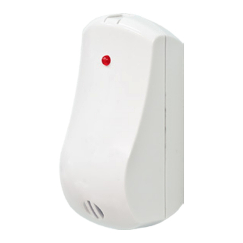
WIRELESS MAGNETIC CONTACT
SECURITY DETECTORS
«Ladoga MK-RK»
«Ladoga MK-RK» version 1
1 General Information
1.1 Wireless magnetic contact security Detectors «Ladoga MK-RK»
and «Ladoga MK-RK» version 1 (hereinafter, the Detectors) are
intended for opening or shifting control of doors, windows or
other structural elements with transmission of messages to the
control panel (hereinafter, CP) via two-way wireless channel by
the «Rielta-Contaсt-R» protocol.
1.2 Opening or shifting control is fulfilled by built-in magnetic
contact monitoring. The Detectors comprise the plugs for external
inertia detectors (hereinafter, the EID) hooking up.
1.3 Two versions of Detectors are manufactured:
- «Ladoga MK-RK» – single-zone, provides a possibility for one EID
hooking up to «G 1» loop;
- «Ladoga MK-RK» version 1 – two-zone, provides a possibility for
two EID hooking up to «G 1» and «G 2».
The built-in Gerkon and «G 1» loop are integrated in a single control
zone, operation tactics of which is set by the «ХР2» jumper (see Cl. 8).
1.4 Detectors operate within 433.05 – 434.79 MHz frequency range.
Their transmission power does not exceed 10 mW.
1.5 The Detectors ensure operation at the main and backup
operating frequencies. The changeover to backup operating frequency
is fulfilled automatically.
1.6 Radio communication is initiated by the Detectors at 10, 15, 30 sec
,
1, 5, 10 min intervals assigned in the process of their binding with the
CP. Alarm and tamper messages are transmitted immediately.
1.7 The Detectors are powered from main (СR123А) and backup
(СR2450) power supply batteries.
1.8 Operation modes of the Detectors are displayed by a two-color
LED indicator. The detector «Ladoga MK-RK» version 1 provides
complementary sound indication of the Detector state.
1.9 The Detectors generate and transmit the following messages:
- «Norm» – under closed built-in magnetic contacts and «G 1» loop
resistance value in the range 3.6 … 6.5 kΩ;
- «Intrusion to Zone 1» – under opened built-in magnetic contacts
and «G 1» loop resistance value less than 3.4 or more than 6.9 kΩ;
- «Tamper» – in the event of case tampering or removal from the
installation surface;
- «Main Power Supply Low Battery» – under the main power supply
battery voltage drop over 2.2-0.2 V;
- «Backup Power Supply Low Battery» – under the backup power
supply battery voltage drop over 2.2-0.2 V.
1.10 The Detectors are designed to operate continuously, around
the clock.
1.11 The Detectors have immunity to electromagnetic interference.
2 Specifications
Table 1
Parameter Value
Distance between the Detector and the magnet, mm:
- for magnetic contact opening
- for magnetic contact restoration
more than 15
less than 5
Monitored loop resistance range, kΩ
- in the «Norm» state
- in the «Alarm» state
3.6 to 6.5
less than 3.4 or more
than 6.9
Operating temperatures range, °C minus 20 to +55
Permissible relative humidity at 25 °C temperature, % up to 98
Dimensions, mm, max 112 x 41 x 32
Weight, kg, max 0.1
Average service life, years 8
The operation duration under normal climate conditions and
specified broadcast period than 30 sec, not less:
- main power supply battery, months
- backup power supply battery, months
60
2
IP rating IP30
3 Scope of Delivery
The scope of delivery is listed in the Table 2.
Table 2
Name
Version
- -01
Wireless magnetic contact security Detector «Ladoga MK-RK»
Wireless magnetic contact security Detector «Ladoga MK-RK»
version1
СR123А power supply battery
СR2450 power supply battery
Magnetic contact inertia security Detector
Resistor 5.1 kΩ0.125 W
Screw 3-3х30.016
Wireless magnetic contact security Detectors «Ladoga MK-RK».
Installation Guide
1 pc.
1 pc.
1 pc.
1 pc.
1 pc.
6 pcs.
1 copy
1 pc.
1 pc.
1 pc.
2 pc.
2 pcs.
10 pcs.
1 copy
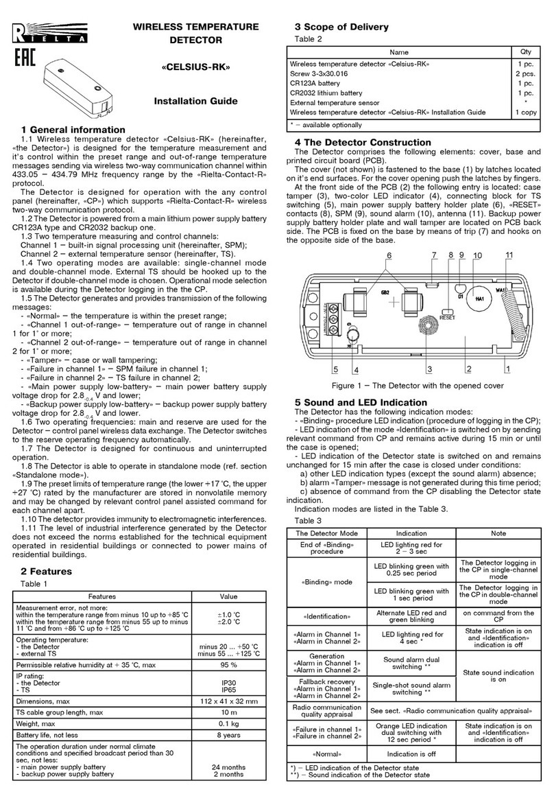
4 Design of the Detector
The Detector consists of a case and a printed circuit board
(PCB). On the front side of the PCB (1) there are located: antenna
(2), builtin hermetic contact (3), jumper «ХР2» (5), tamper (4), two-
color LED indicator (7), terminal blocks for EID hooking up (8), main
battery holder (9), backup battery holder (12), «RESET» contacts
(11). There is a sound indicator situated on the face side of the
«Ladoga MK-RK» version 1. Tamper is located on the back side of PCB.
PCB is fixed on the base by a latch (10).
Magnet (6) of the inertial detector (supplied) is used for the built-in
hermetic contact control. The magnet should be installed opposite to
the recess in the sidewall of the base.
Figure 1
5 Indication
The following types of indication are generated by the Detectors:
a) «Binding» – procedure of logging of the Detector in the CP;
b) «Identification»indication is activated by relevant commands
received from the CP, remains active during 15 min or until the Detector
cover is opened;
c) LED indication of the Detector state is activated after the Detector
cover is closed and remains active during 15 min under conditions:
- other LED indication types absence;
- alarm «Tamper» message is not generated during this time;
- absence of command from the CP disabling the Detector state
indication.
Sound indication (only for «Ladoga MK-RK» version 1) is activated
by the relevant command from the CP.
The types of LED indication are listed in the Table 3.
Table 3
The Detector State Indication Note
End of the «Binding» procedure LED indicator lighting
red for 2 – 3 sec
«Binding» procedure LED indicator lighting
green
The Detector logging in
the CP
«Identification» indication LED indicator alternate
blinking red and green
By the relevant command
from the CP
«Intrusion to Zone 1»
«Intrusion to Zone 2»
Single-shot LED
indicator lighting red for
4 sec*
State indication is ON,
«Identification» indication
is OFF
Installation Guide
а) «Ladoga MK-RK» b) «Ladoga MK-RK» version 1
11
1
2
4
3
5
6
7
8
9
10
СБРОС
ГЕРКОН ВНУТР.
ВНЕШ.
12
11
1
2
4
3
5
6
7
8
9
10
12
13
2 G 1
2 G 1
Roк
Roк
Roк
●
Inside
Outside
Inside
Outside
External detector
Magnet
Magnet
External detector
