Rielta Ochrana FOTON-19RK User manual

6 Informativity
The Detector ensures transmission and indication of the following
messages:
- normal state message;
- alarm message;
- tamper message;
- main power-supply low-battery message;
- backup power-supply low-battery message;
- «Binding» mode indication;
- «Identification» mode indication;
- communication quality indication.
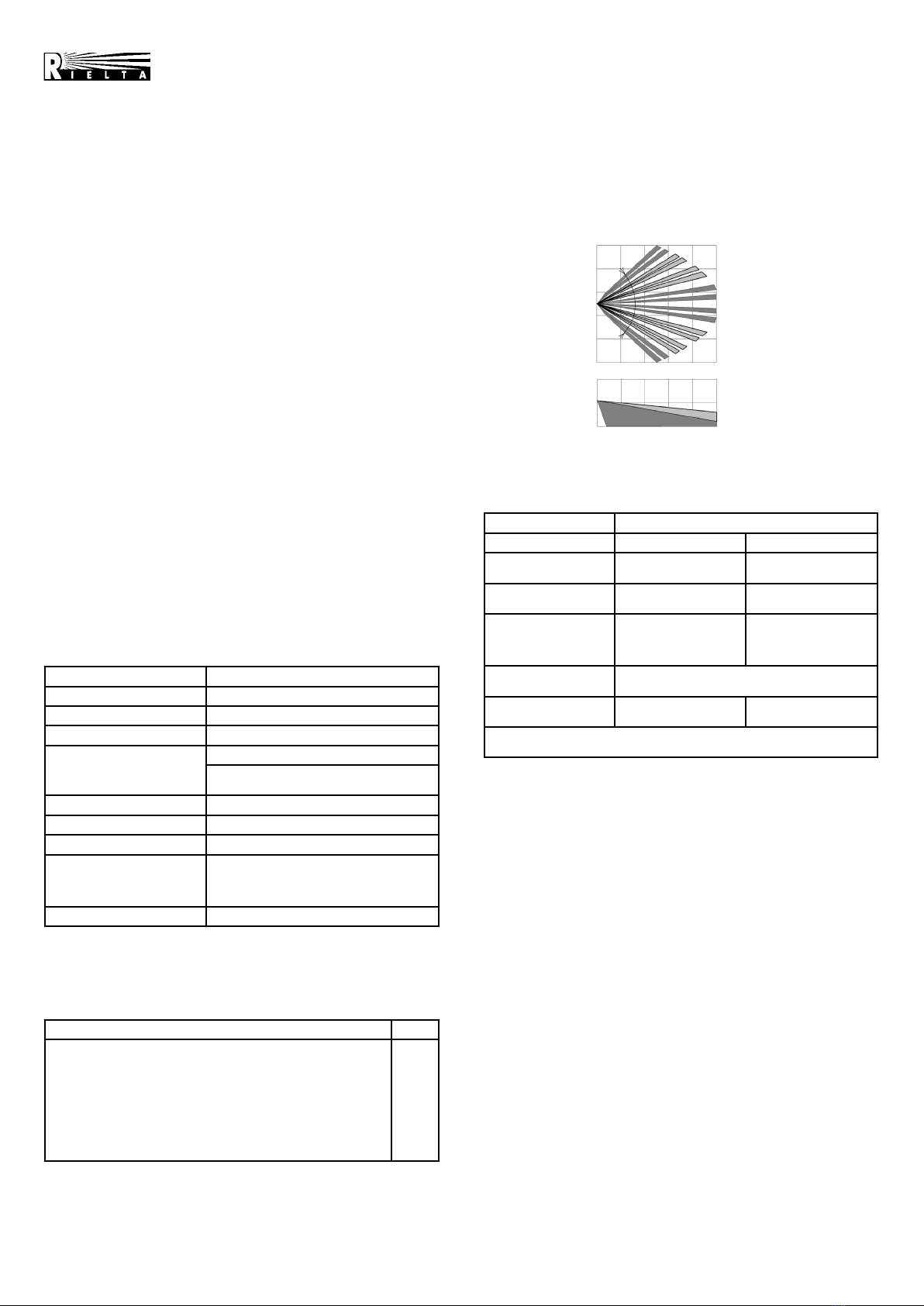
7 Detection Pattern
1 Introduction
Wireless passive infrared detector «Foton-19RK» (hereinafter, the
Detector) is intended for detecting intrusion into a closed protected
space and generating an alarm message.
The Detector highlights:
- generates status messages via a two-way wireless channel
within the 433.05 — 434.79 MHz frequency range according to
«Rielta-Contact-R» wireless two-way data exchange protocol;
- is intended to operate as a component of a system that is operated
by any control panel (hereinafter, CP) supporting «Rielta-Contact-R»
wireless two-way data exchange protocol;
- ensures case tamper protection;
- is resistant to the ambient light impact and radio interference;
- does not generate false alarms caused by the movement of:
a) short-haired pets weighting up to 20 kg (with temperature
contrast 8 °С);
b) long-haired pets weighing up to 40 kg (with temperature
contrast 6 °С);
- the Detector is installed directly on a wall or in a corner of a room.
2 Features of the Detector
- Dual-element pyrodetector.
- Distortions preventation in the detection zone by means of
spherical lens.
- Pet immunity.
- Protection against ingress of insects to the pyroelectric.
- Pet immunity adjustment (10, 20 or 40 kg pet weight).
- Automatic switching to a backup operating frequency in case of
an imperfect interference situation on the main one.
- Built-in main and backup power supply.
3 Specifications
Table 1
Features Value
Detection zone size 10 x 10 m
Detection zones 8 long-range zones, 4 short-range zones
Maximum detection range 10 m
Pet immunity
Jumper «10kg» installed — 10 kg
Jumper «10kg» removed — 20 kg (contrast
8 °С) or 40 kg (contrast 6 °С)
Operating temperature from minus 20 °С to +50 °С
Dimensions, maximum 105 х 75 х 56 mm
Weight, maximum 0.1 kg
Battery life (under normal
climatic conditions and with a
radio exchange period equal
to at least 30 sec)
up to 5 years
IP rating IP41
The Detector is powered by a main lithium power-supply battery
СR123A type and СR2032 backup one.
4 Scope of Delivery
Each Detector unit package contains the items listed in Table 2.
Table 2
Name QNT
Wireless passive infrared detector «Foton-19RK»
Screw 3-3х30.016
Wall plug NAT 5х25 SORMAT
Screw 2,9х6,5 DIN7981F
СR123A lithium power supply battery
СR2032 lithium power supply battery
Wireless passive infrared detector «Foton-19RK». Installation
Guide
1 pc.
2 pcs.
2 pcs.
1 pc.
1 pc.
1 pc.
1 copy
5 Field of Application
The Detector can be installed in apartments, as well as in shops,
offices, museums and industrial facilities. The Detector may be
installed in premises, that are inhabited by pets weighing up to
40 kg (20 kg).
WIRELESS PASSIVE INFRARED
DETECTOR
WITH PET IMMUNITY
«FOTON-19RK»
Installation Guide
Top View
Side View
Figure 1
8 LED Indication
Table 3
Detector State LED Indication
«Binding» LED status Operation mode
«Alarm»* LED indicator blinks
green
«Identification» LED indicator lights red
for at least 0.5 sec if indication is enabled
«Connection quality»
LED indicator blinks
red and green
alternately at 1 Hz
frequency
by a command from
the CP
Binding procedure
completed See «Communication Quality Appraising»
Binding procedure
completed
LED indicator lights red
for 2 sec
*) — Alarm indication is deactivated 15 min after the Detector cover is closed
and activated after it has been opened or by a command from the CP.
9 Binding with the CP
The Binding procedure is intended for logging of the Detector in the
CP and transmission of service information to it.
9.1 Prepare the CP for the Detector logging in accordance to the
CP manual.
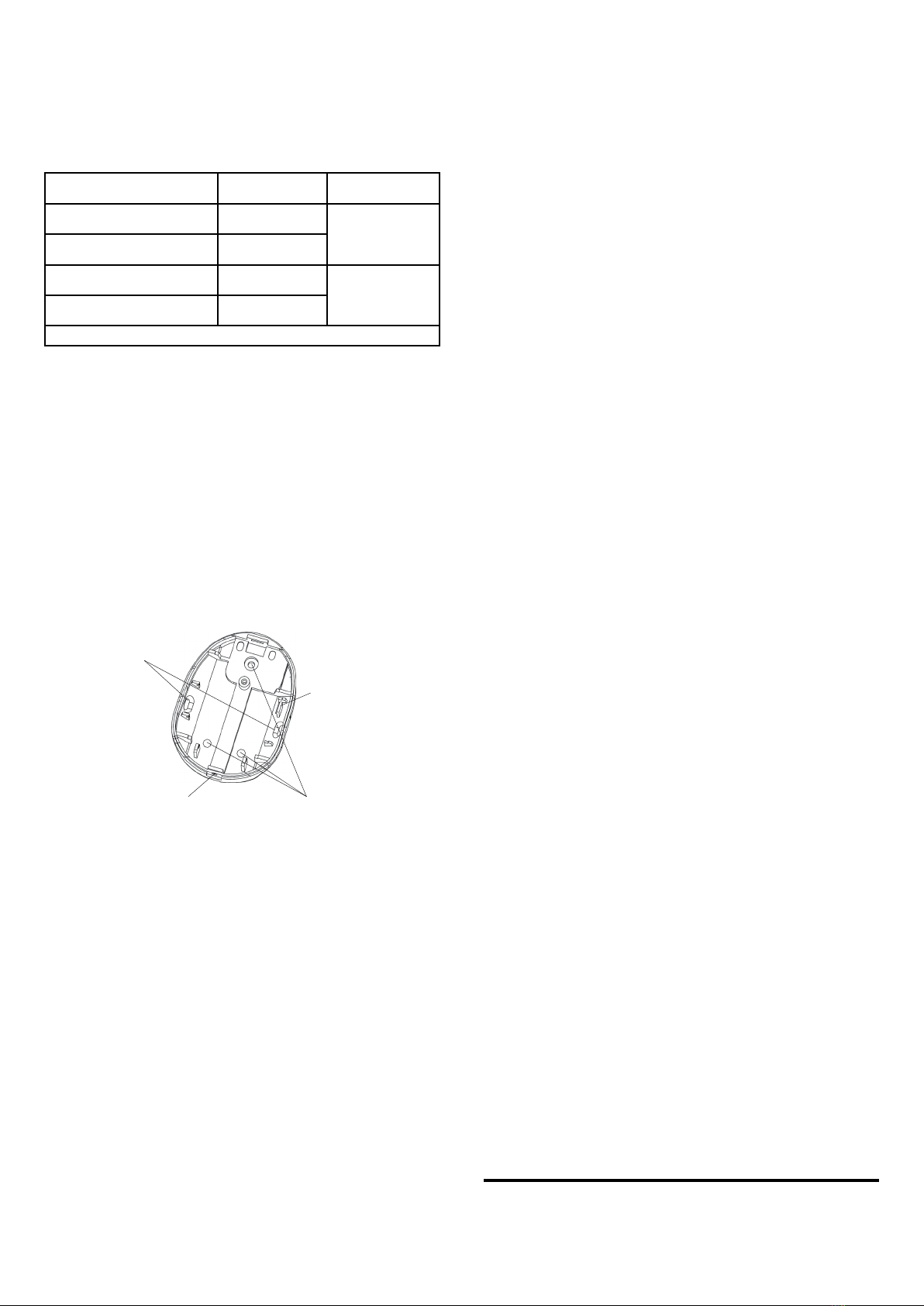
9.2 Install the СR2032 backup power-supply battery into the holder
located on the reverse side of the Detector printed circuit board (PCB).
9.3 Install the PCB into the Detector case, and then install the
СR123А main power-supply battery.
9.4 Blinking of the LED indicator green displays the Detector
readiness for the binding procedure. In case the LED indicator does
not blink, close the «Reset» contacts for a short period.
9.5 After a successful binding with the CP, the LED indicator lights
red for 2 sec.
9.6 The «Binding» procedure is limited to 100 sec. After it expires,
the Detector switches to the sleep mode. To resume the «Binding»
mode, the «Reset» contacts should be temporary closed.
10 Choosing an Installation Place for the Detector
The Detector must be located in the radio-coverage zone of it’s
CP. Therefore, it is advisable to appraise quality of communication
beforehand. The procedure of communication quality appraising is
described in the chapter «Communication Quality Appraising».
When choosing the Detector installation place, it is advisable
to take note of the fact that the detection zone may be limited by
non-transparent objects (curtains, houseplants, cabinets, bookcases,
etc.), as well as glass and mesh partitions. There must be no windows,
air conditioners, space heaters or heating radiators in the Detector
visibility zone. The presence of furniture items on which an animal may
climb in the detection zone may cause a false alarm.
Recommended installation height —2.3 m from the floor.
The Detector should be installed at least 0.5 m distance from
electric cables.
10 m
10 m
2.3 m
0
0
90о

14 Detector Behavior
14.1 The Detector is powered on and off by installation and removal
of the main power-supply battery.
14.2 After loss of communication with the CP, the Detector will
continue to search for the CP. In case the CP is disabled for a long
time, it is recommended to power off the Detector (see Cl. 14.1).
14.3 It must be taken into account, that in case of the Detector
operation within +5 °C to minus 20 °C temperature range, the battery
life may be less than 5 years.
ATTENTION! The Detector must be checked at least annually in
order to test it’s performance.
15 Storage and Transportation
15.1 The Detectors in their original packing may be shipped by any
transport means in covered vehicles (in railway, cars, trucks, sealed
heated compartments of aircraft, ship cargo holds, etc). The Detector
is resistant to:
а) transport jolting with the acceleration 30 m/sec2with impact
frequency from 10 to 120 impacts/sec or 15000 impacts with the same
acceleration;
b) the ambient temperature minus 50 … +50 °С;
c) relative air humidity (95 ± 3) % at the ambient temperature +35 °С.
15.2 After transportation under the conditions different to exploitation
conditions the Detector shall be ready to operate after a maximum
of six hours.
15.3 The storage room shall be free from current-conducting
dust, acid vapors, alkali and gases that cause corrosion and destroy
insulation.
16 Manufacturer’s Guarantees
16.1 The Manufacturer guarantees conformity of the Detector to
its Technical Specifications if conditions of transportation, storage,
assembling and operation are observed. The guaranteed storage
period is 63 months since the date of manufacturing the Detector.
16.2 The guaranteed period of operation is 60 months since the date
of commissioning within the storage period guaranteed.
16.3 The Detectors that are found to non-conforming to their
Technical Requirements shall be repaired by the Manufacturer,
provided that the installation and operation rules have been complied
with.
Note — Warranty obligations are not applied to the power-supply
batteries.
17 Acceptance and Packing Certificate
Wireless passive infrared detector «Foton-19RK»,
lot No __________________________,
manufactured in accordance with current technical documentation
is classified as fit for operation and is packed by «RIELTA» JSC.
Person responsible for acceptance and packing
Representative of QCD ________________ __________________.
Date, month, year
11 Communication Quality Appraising
Before installing the Detector to it’s place of operation, it is advisable
to appraise the CP communication quality as follows.
11.1 Prepare the Detector for operation and put it on its location
place with a closed cover.
11.2 Open the Detector case, whereupon the Detector will indicate
the quality of CP communication.
Table 4
LED indication Communication
Quality Appraisal Recommendations
LED indicator blinks green
three times Excellent Install the Detector
at this place
LED indicator blinks green two
times Good
LED indicator blinks green one
time
Communication
established Choose another
place of installation
or use a repeater*)
LED indicator blinks red four
times No communication
*) — «Ladoga BRSS-RK-RTR» or «Ladoga BRSS-RK-RTR» ver. 1
12 Installing the Detector
Before installing the Detector, remove it’s cover and the PCB. For
this purpose:
- remove the cover of the Detector;
- loosen the screw fastening the PCB, move it upwards and remove
it from the Detector base;
- drill the holes (Figure 2) in the base of the Detector case. They
will be used for fastening the Detector;
- choose the installation place, mark out and drill the installation
places in the wall with regard for the position of the holes on the
Detector base;
- fasten the Detector base in the chosen place;
- reinstall the PCB;
- put on the cover, screw in the retainer screw 2.9x6.5 DIN7981F
(supplied).
Note — To exclude false alarms in the pet immunity mode, the
Detector should be installed vertically.
«RIELTA» JSC, www.rielta.ru,
Tel./fax. +7 (812) 233-0302, 703-1360,
Made in Russia
Rev. 3 of 10.11.14
V.7.1
Figure 2
13 Functional Testing
In presence of the pets weighing up to 40 kg in the room, remove
the «10 kg» jumper, in presence of the pets weighting less than 10 kg
in the room, install the «10 kg» jumper.
It is advisable to remove the «10 kg» jumper in the premises with a
high interference level.
Start walking across the detection zone. After 3 — 4 steps across
the detection zone, the Detector should display the detection by the
LED indicator red blink. Wait for 10 sec and continue walking across
the detection zone. There must be no indication in absence of moving
objects in the room. If the Detector fails to detect moving objects in the
detection zone, it’s position on the swivel bracket should be changed.
Base
Holes for
fastening in a
corner
Hole for the PCB
fashening screw
Holes for installation
on a wall
Location of the
fastening
Other Rielta Security Sensor manuals

Rielta
Rielta CELSIUS-RK User manual

Rielta
Rielta PYRONE-4i User manual

Rielta
Rielta GRAN-RK User manual

Rielta
Rielta Ochrana ORLAN-D User manual

Rielta
Rielta Ladoga MK-RK User manual

Rielta
Rielta PYRONE-SH User manual

Rielta
Rielta FOTON-SH2-RK User manual

Rielta
Rielta FOTON-SH1 User manual

Rielta
Rielta ZVON-1 User manual

Rielta
Rielta C.Nord CN-Flood-Mini User manual

Rielta
Rielta FOTON-15B User manual

Rielta
Rielta ORLAN-2 User manual

Rielta
Rielta FOTON-10M User manual

Rielta
Rielta FOTON-16B User manual

Rielta
Rielta ZVON-1 User manual

Rielta
Rielta C.Nord CN-PIR User manual

Rielta
Rielta UDAR User manual

Rielta
Rielta ORLAN-D User manual

Rielta
Rielta STZ-RK User manual

Rielta
Rielta CELSIUS-RK User manual