manuals.online logo
Brands
  1. Home
  2. •
  3. Brands
  4. •
  5. Rielta
  6. •
  7. Security Sensor
  8. •
  9. Rielta Ladoga MK-RK User manual

Rielta Ladoga MK-RK User manual

WIRELESS MAGNETIC CONTACT
SECURITY DETECTOR
«Ladoga MK-RK» ver. 3
1 General Information
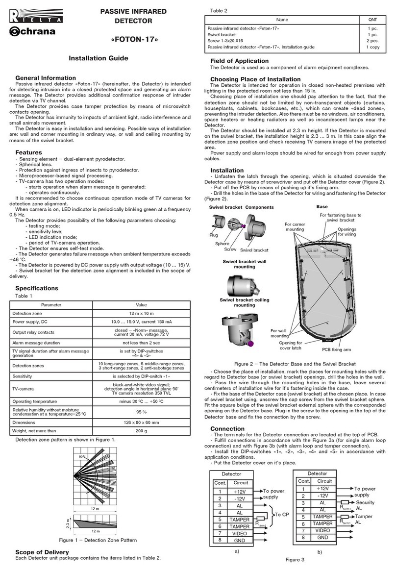
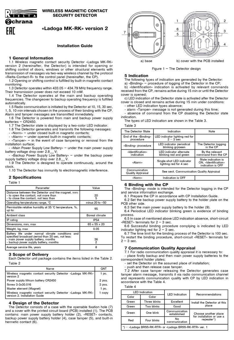
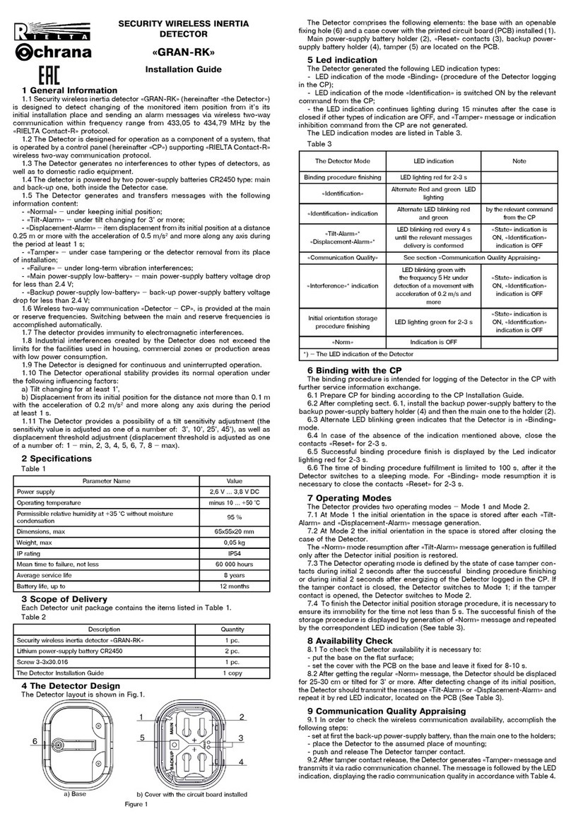
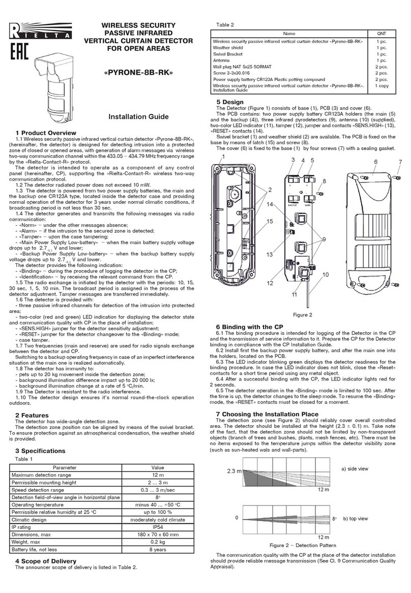
1.1 Wireless magnetic contact security Detector «Ladoga MK-RK»
ver. 3 (hereinafter, the Detector) is intended for opening or shifting
control of doors, windows or other structural elements with transmission
of messages to the control panel (hereinafter, CP) via two-way wireless
communication by the «Rielta-Contaсt-R» protocol.
1.2 Opening or shifting control is fulfilled by built-in magnetic contact
monitoring. The Detector comprises the plugs for external inertia
detectors (hereinafter, the EID) hooking up.
1.3 The Detector is – single-zone, provides a possibility for one EID
hooking up to «G 1» loop.
The built-in Gerkon and «G 1» loop are integrated in a single control
zone, operation tactics of which is set by the «ХР2» jumper (see Cl. 8).
1.4 The Detector operates within 433.05 – 434.79 MHz frequency
range. Transmission power does not exceed 10 mW.
1.5 The Detector ensures operation at the main and backup operating
frequencies. The changeover to backup operating frequency is fulfilled
automatically.
1.6 Radio communication is initiated by the Detector at 10, 15, 30 sec
,
1, 5, 10 min intervals assigned in the process of their binding with the
CP. Alarm and tamper messages are transmitted immediately.
1.7 The Detector is powered from the one lithium power supply
battery CR123A.
1.8 Operation modes of the Detector are displayed by a two-color
LED indicator.
1.9 The Detector generates and transmits the following messages:
- «Norm» – under closed built-in magnetic contacts and «G 1» loop
resistance value in the range 3.6 … 6.5 kΩ;
- «Intrusion to Zone 1» – under opened built-in magnetic contacts
and «G 1» loop resistance value less than 3.4 or more than 6.9 kΩ;
- «Tamper» – in the event of case tampering or removal from the
installation surface;
- «Power Supply Low Battery» – under the power supply battery
voltage drop over 2.2-0.2 V;
1.10 The Detector is designed to operate continuously, around the
clock.
1.11 The Detector has immunity to electromagnetic interference.
2 Specifications
Table 1
Parameter Value
Distance between the Detector and the magnet, mm:
- for magnetic contact opening
- for magnetic contact restoration
more than 15
less than 5
Monitored loop resistance range, kΩ:
- in the «Norm» state
- in the «Alarm» state
3.6 to 6.5
less than 3.4 or more
than 6.9
Operating temperatures range, °C
minus 20 to +55
Permissible relative humidity at 25 °C temperature, % up to 98
Dimensions, mm, max 112 x 41 x 32
Weight, kg, max 0.1
IP rating IP30
Ambient class Boreal climate
Battery life under normal climatic conditions, disabled
indication and assigned radio exchange period not
less than 30 sec: months, not less 60
Average service life, years 8
3 Scope of Delivery
Each Detector unit package contains the items listed in the Table 2.
Table 2
Name
QNT
Wireless magnetic contact security Detector «Ladoga MK-RK» ver. 3
Power supply lithium battery CR123A
Magnetic contact inertia security Detector
Resistor 5.1 kΩ0.125 W
Wireless magnetic contact security Detector «Ladoga MK-RK» ver. 3.
Installation Guide
1 pc.
1 pc.
1 pc.
1 pc.
1 copy
4 Design of the Detector
The Detector consists of a case and a printed circuit board (PCB).
On the front side of the PCB (1) there are located: antenna (2), builtin
hermetic contact (3), jumper «ХР2» (5), tamper (4), two-color LED
indicator (7), terminal blocks for EID hooking up (8), battery holder (9),
«RESET» contacts (11). The PCB is fixed on the base with a latch (10).
Magnet (6) of the inertial detector (supplied) is used for the built-in
hermetic contact supervision. The magnet should be installed opposite
to the recess in the sidewall of the base.
External
detector
Figure 1 – «Ladoga MK-RK» ver. 3
5 Indication
The following types of indication are generated by the Detector:
a) «Binding» – procedure of logging of the Detector in the CP;
b) «Identification»indication is activated by relevant commands
received from the CP, remains active during 15 min or until the Detector
cover is opened;
c) LED indication of the Detector state is activated after the Detector
cover is closed and remains active during 15 min under conditions:
- other LED indication types absence;
- alarm «Tamper» message is not generated during this time;
- absence of command from the CP disabling the Detector state
indication.
The modes of LED indication are listed in the Table 3.
Table 3
The Detector State Indication Note
End of the «Binding»
procedure
LED indicator lighting red
for 2 – 3 sec
«Binding» procedure LED indicator periodical
blinking green
The Detector logging
in the CP
«Identification»
indication
LED indicator alternate
blinking red and green
By the relevant
command from the
CP
«Intrusion to Zone 1» Single-shot LED indicator
lighting red for 4 sec*
State indication is
ON, «Identification»
indication is OFF
Communication
Quality Appraisal See sect. Communication Quality Appraising
«
Norm
» Indication is OFF
* – LED indication of the Detector
6 Binding with the CP
The «Binding» mode is intended for the Detector logging in the CP
and service information exchange.
6.1 Prepare the CP in accordance with CP Installation Guide.
6.2 Place the power supply battery to the holder (9) (if the battery is
installed by manufacturer, remove an isolator).
6.3 Periodical LED indicator blinking green is evidence of binding
process.
6.4 In case of mentioned above LED indication absence, short-circuit
«RESET» terminals for 2 – 3 sec.
6.5 Successful binding procedure complying is indicated by LED
indicator lighting red for 2 – 3 sec.
6.6 The time limit for the binding process of the Detector is 70 sec.
To restart the binding procedure, short-circuit «RESET» terminals for
2 – 3 sec.
7 Communication Quality Appraising
7.1 For radio communication quality appraising it is necessary to:
- install the PCB to the base;
- set the Detector on the assumed place of installation;
- push and then release case tamper.
7.2 After case tamper releasing the Detector generates case
tamper alarm message, transmits it via radio communication channel
and represents communication quality with CP by LED indication in
accordance with the Table 4.
Installation Guide
11 12
43
67
8910
5
2 G 1
Reset
Roк
Inside
Outside
Magnet
Rev. 4 of 17.05.18
v.12
«RIELA» JSC, www.rielta.ru,
17 Chapayeva St., Saint Petersburg, Russia, 197101, [email protected],
tel./fax: +7 (812) 233-0302, 703-1360,
Technical support: tel.: +7 (812) 233-29-53, 703-13-57, [email protected]
Made in Russia
Table 4
LED Indication Communication
Quality Appraisal Recommendations
Color Mode
Green Three blinks Excellent Install the Detector at
this place
Green Two blinks Good
Green One blink Communication
established Choose another place
for installation or use a
repeater*)
Red
Series of blinks
No
communication
*) – «Ladoga-RK» system repeater
9 Installation
9.1 Choose the place of installation. Mark the holes layout, for the
purpose the base of the Detector can be used (see Figure 2). Fasten
the base by screws. To ensure wall tampering control, fasten the
screw in the wall tamper holder.
9.2 Install the PCB, connect the wires of monitored loops to
terminal blocks (8) and close the cover. The length of the loops must
not exceed 5 m. Install the terminal (EOL) resistor Rterm (5.1 kΩ) at
the end of the loop as shown in Figure 1. The connections must be
soldered or screwed.
Fixation holes
for the base
fastening to
the mounting
surface
10 Storage and Transportation
10.1 The detector are transported without power supply battery. The
detector in their original packaging are resistant to:
- transport jolting with the acceleration up to 30 m/sec2at impact
frequency range from 10 to 120 per minute or 15 000 strikes;
- ambient temperature range minus 50 ... +50 °С;
- relative air humidity (95 ± 3) % at a temperature +35 °С.
10.2 The detector in original package may be transported by any
means of transportation in closed vehicles over any distances in compli-
ance with the existing shipping rules concerning the respective means
of transportation.
10.3 After transportation under the conditions different to exploita-
tion conditions the detector shall be ready to operate after a maximum
of six hours.
10.4 The storage room shall be free from current-conducting dust,
acid vapors, alkali and gases that cause corrosion and destroy insulation.
11 Manufacturer’s Guarantees
11.1 The Manufacturer guarantees conformity of the Detector to
it’s Technical Specifications if conditions of transportation, storage,
assembling and operation are observed. The guaranteed storage period
is 63 months since the date of manufacturing the Detector.
11.2 The guaranteed period of operation is 60 months since the date
of commissioning within the storage period guaranteed.
11.3 The Detectors that are found to non-conforming to it’s Technical
Requirements shall be repaired by the Manufacturer, provided the
installation and operation rules have been complied with.
Note –Warranty obligations are not applied to the power supply
battery.
12 Acceptance and Packing Certificate
Wireless magnetic contact security Detector «Ladoga MK-RK»
ver. 3
has been manufactured in compliance with the active technical
documentation and classified as fit for operation and packed by
«RIELTA» JSC.
Packing date _______________________________
month, year
Antenna
holder plate
9.3 It is not recommended to install
the Detectors on metal surfaces. The
distance between the Detector and a
magnet or magnetically conductive
material should be at least 25 mm.
9.4 Irrespectively of any permissible
positions of the monitored structure,
the Detector and the magnet should
not be subjected to mechanical impacts
(compression, blows, etc.).
Figure 2 – The Base
9.5 In case of simultaneous usage of a built-in hermetic contact and
an external detector plugged to «G 1»contacts, remove «XP2» jumper.
Attention! Antenna should be installed to the antenna holder plate
(see Figure 2). The antenna location outside of antenna holder plate
essentially reduces radio communication range.

Other Rielta Security Sensor manuals

Rielta STZ-RK User manual

Rielta

Rielta STZ-RK User manual

Rielta Ladoga MK-RK User manual

Rielta

Rielta Ladoga MK-RK User manual

Rielta FOTON-SH1 User manual

Rielta

Rielta FOTON-SH1 User manual

Rielta PYRONE-8B-RK User manual

Rielta

Rielta PYRONE-8B-RK User manual

Rielta ZVON-1 User manual

Rielta

Rielta ZVON-1 User manual

Rielta Pyrone-4RK User manual

Rielta

Rielta Pyrone-4RK User manual

Rielta FOTON-16B User manual

Rielta

Rielta FOTON-16B User manual

Rielta ZVON-1 User manual

Rielta

Rielta ZVON-1 User manual

Rielta PYRONE-8B-RK User manual

Rielta

Rielta PYRONE-8B-RK User manual

Rielta PYRONE-5 User manual

Rielta

Rielta PYRONE-5 User manual

Rielta ORLAN-2 User manual

Rielta

Rielta ORLAN-2 User manual

Rielta SH-V User manual

Rielta

Rielta SH-V User manual

Rielta STEKLO-3RK User manual

Rielta

Rielta STEKLO-3RK User manual

Rielta ZVON-1 User manual

Rielta

Rielta ZVON-1 User manual

Rielta Pyrone-7 User manual

Rielta

Rielta Pyrone-7 User manual

Rielta PYRONE-8-RK User manual

Rielta

Rielta PYRONE-8-RK User manual

Rielta STEKLO-2 User manual

Rielta

Rielta STEKLO-2 User manual

Rielta STZ-RK User manual

Rielta

Rielta STZ-RK User manual

Rielta C.Nord CN-Flood-Mini User manual

Rielta

Rielta C.Nord CN-Flood-Mini User manual

Rielta STEKLO-3RK User manual

Rielta

Rielta STEKLO-3RK User manual

Rielta STZ-RK User manual

Rielta

Rielta STZ-RK User manual

Rielta IPDL-Ex User manual

Rielta

Rielta IPDL-Ex User manual

Rielta PYRONE-SH User manual

Rielta

Rielta PYRONE-SH User manual

Rielta FOTON-12-RK User manual

Rielta

Rielta FOTON-12-RK User manual

Popular Security Sensor manuals by other brands

Ecolink PIR-ZWAVE2 installation instructions

Ecolink

Ecolink PIR-ZWAVE2 installation instructions

Alarmtech GD 370 Installer manual

Alarmtech

Alarmtech GD 370 Installer manual

Nice LP21 User, installation and safety instructions

Nice

Nice LP21 User, installation and safety instructions

Elkay Ceilingmountpir Fitting and operating instructions

Elkay

Elkay Ceilingmountpir Fitting and operating instructions

Honeywell SPM Flex user manual

Honeywell

Honeywell SPM Flex user manual

LEGRAND Mosaic 0 489 22 manual

LEGRAND

LEGRAND Mosaic 0 489 22 manual

BFT RIP installation manual

BFT

BFT RIP installation manual

MICRO-EPSILON capaNCDT 6228 operating instructions

MICRO-EPSILON

MICRO-EPSILON capaNCDT 6228 operating instructions

Emos G1160 quick start guide

Emos

Emos G1160 quick start guide

IMMOOS SS1 oGB operating instructions

IMMOOS

IMMOOS SS1 oGB operating instructions

Pilz PSEN 2.1p-20 operating manual

Pilz

Pilz PSEN 2.1p-20 operating manual

Satel COBALT quick start guide

Satel

Satel COBALT quick start guide

Radiodetection 1205CXB Operation manual

Radiodetection

Radiodetection 1205CXB Operation manual

Elkron EIR600FC Installation, programming and functions manual

Elkron

Elkron EIR600FC Installation, programming and functions manual

Besantek BST-HVD9 instruction manual

Besantek

Besantek BST-HVD9 instruction manual

LUDLUM 70 System manual

LUDLUM

LUDLUM 70 System manual

Bosean Electronic Technology BH-4S user manual

Bosean Electronic Technology

Bosean Electronic Technology BH-4S user manual

hager TX510 Setup instructions

hager

hager TX510 Setup instructions

manuals.online logo
manuals.online logoBrands
  • About & Mission
  • Contact us
  • Privacy Policy
  • Terms and Conditions

Copyright 2025 Manuals.Online. All Rights Reserved.