Riken Keiki GM-600 User manual

PT2E-2350
E.O. Gas Monitor
GM-600
Operating Manual

2
Contents
1. Outline of the Product..................................................................................................................................... 3
Preface............................................................................................................................................................ 3
Purpose of use................................................................................................................................................ 3
Definition of DANGER, WARNING, CAUTION and NOTE ............................................................................ 4
Method of confirmation for CE marking type .................................................................................................. 4
2. Important Notices on Safety........................................................................................................................... 5
2-1. Danger cases........................................................................................................................................... 5
2-2. Warning cases ......................................................................................................................................... 6
2-3. Precautions.............................................................................................................................................. 6
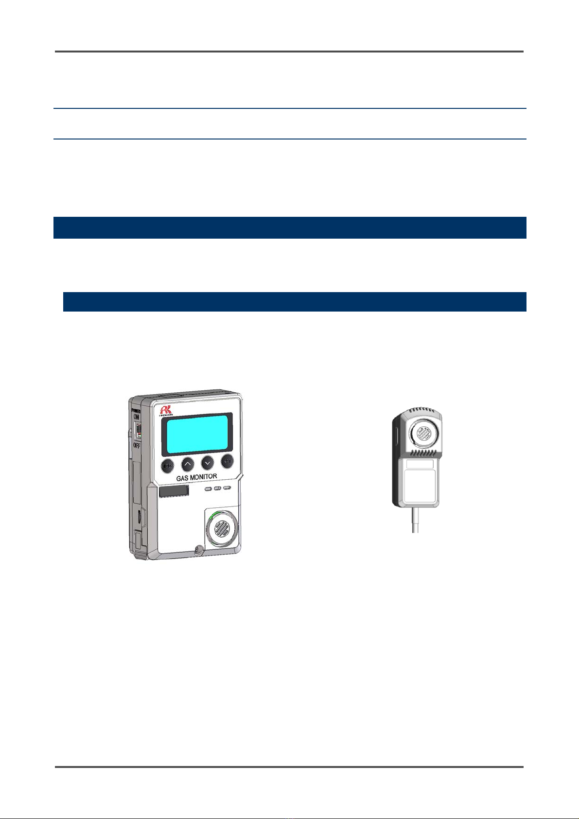
3. Product Components...................................................................................................................................... 7
3-1. Main unit and standard accessories........................................................................................................ 7
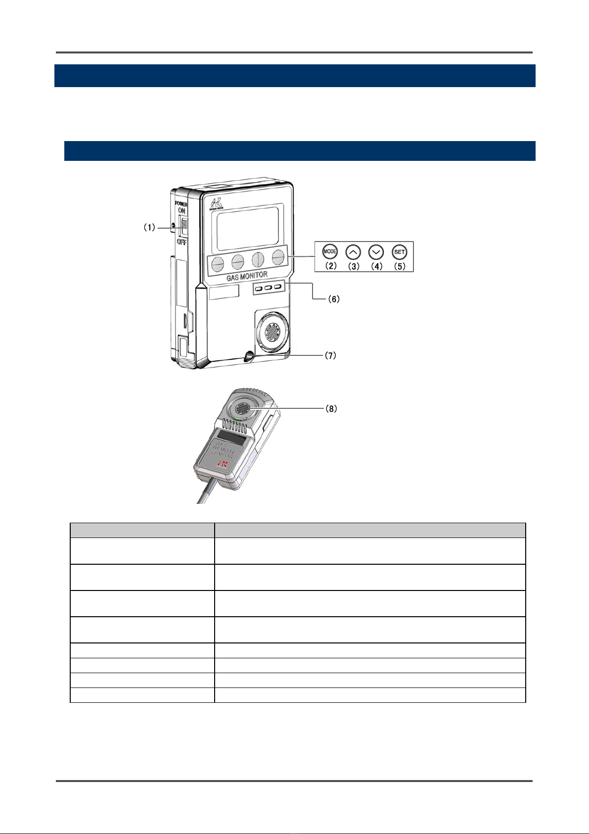
3-2. Names and functions for each part ......................................................................................................... 9
4. How to Install Gas Monitor ........................................................................................................................... 11
4-1. Precautions for installation points ......................................................................................................... 11
4-2. Precautions for system designing .........................................................................................................12
4-3. Installation of monitor ............................................................................................................................14
4-4. Precautions for wiring ............................................................................................................................17
5. How to Use ...................................................................................................................................................20
5-1. Before using the monitor .......................................................................................................................20
5-2. Preparation for start-up ......................................................................................................................... 20
5-3. Basic operating procedures................................................................................................................... 21
5-4. Power-on ...............................................................................................................................................22
5-5. Modes ....................................................................................................................................................23
5-6. User mode .............................................................................................................................................24
5-7. Power-off ...............................................................................................................................................26
6. Alarm Activation and Functions ....................................................................................................................27
6-1. Gas alarm activation.............................................................................................................................. 27
6-2. Fault alarm activation ............................................................................................................................29
7. Maintenance .................................................................................................................................................30
7-1. Maintenance intervals and items...........................................................................................................30
7-2. Maintenance (regular maintenance) mode ........................................................................................... 32
8. Storage and Disposal ...................................................................................................................................45
8-1. Procedures to store the monitor or leave it for a long time...................................................................45
8-2. Procedures to relocate the monitor or use it again ...............................................................................45
8-3. Disposal of products ..............................................................................................................................45
9. Troubleshooting ............................................................................................................................................46
10. Product Specifications................................................................................................................................48
10-1. List of specifications ............................................................................................................................48
10-2. List of accessories ...............................................................................................................................48
10-3. Optional accessories ...........................................................................................................................49
11. Appendix .....................................................................................................................................................50
11-1. Detection principle of semiconductor type ..........................................................................................50
11-2. Definition of terms................................................................................................................................ 51

1. Outline of the Product Preface
3
1
1. Outline of the Product
Preface
Thank you for choosing our ethylene oxide (E.O.) gas monitor GM-600 (hereinafter referred to as "the
monitor"). Please check that the model number of the product you purchased is included in the
specifications on this manual.
This manual describes how to use the monitor properly and its specifications. Not only the first-time users
but also the users who have already used the monitor must read and understand the operating manual and
use this product as described in this manual.
Note that the contents of this manual are subject to change without notice for product improvement. It is
also prohibited to copy or reproduce this manual, in whole or in part, without permission.
Regardless of warranty period, we shall not make any indemnification for accidents and damage caused by
using the monitor.
Make sure to read the warranty policy specified on the warranty.
Purpose of use
E.O. gas, which is used for sterilization, is a highly dangerous gas. Even at low gas concentration (allowable
concentration is 1 ppm for ACGIH in 2015 and Japan Society for Occupational Health in 2015), the gas may
adversely affect the human body.
- This is a gas monitor to detect a small amount of E.O. gas leaking from a sterilization device or other
device that uses E.O. gas. The gas monitor is a safety unit, not an analyzer or densitometer which
performs quantitative/qualitative analysis/measurement for E.O. gas.
Please fully understand the features of the monitor before using it, so that it can be used properly.
- This is an E.O. gas monitor to detect E.O. gas leaking from a sterilization device or other device. Do not
use the monitor with it attached to a control device, equipment, etc.
- The monitor notifies of a detected E.O. gas alarm with the buzzer and LCD backlight.
- The monitor has two-step gas alarm contact and fault alarm contact.
- The monitor outputs an alarm contact at a gas alarm state.

1. Outline of the Product Definition of DANGER, WARNING, CAUTION and NOTE
4
Definition of DANGER, WARNING, CAUTION and NOTE
Throughout this manual, the following indications are used to ensure safe and effective work.
DANGER
This message indicates that improper handling may cause serious damage
on life, health or assets.
WARNING This message indicates that improper handling may cause serious damage
on health or assets.
CAUTION This message indicates that improper handling may cause minor damage
on health or assets.
NOTE This message indicates advice on handling.
Method of confirmation for CE marking type
The CE marking is labeled on the detector in case of comply with CE marking. Please confirm the
instrument specification before using. Please refer Declaration of Conformity that is at the end of this
manual if you have CE marking type.
You can confirm instrument specification to see the CE marking as follows.
CE marking label (Bottom of instrument)
(DC specification only)
CE marking

2. Important Notices on Safety 2-1. Danger cases
5
2
2. Important Notices on
Safety
To maintain the performance of the monitor and use it safely, observe the following instructions with
WARNING and CAUTION.
2-1. Danger cases
DANGER
This is not an explosion-proof unit. Never attempt to measure a gas in an atmosphere over the
lower explosive limit.
Do not extend the remote sensor cable. If the cable is extended, the monitor will not be able to
detect gas and may cause dangerous conditions.
WARNING
If an abnormality is found in the monitor, contact RIKEN KEIKI immediately. Visit our Web site to
find your nearest RIKEN KEIKI office.
Web site: http://www.rikenkeiki.co.jp/

2. Important Notices on Safety 2-2. Warning cases
6
2-2. Warning cases
2-3. Precautions
WARNING
Before turning on the monitor, always check that the voltage is compliant with the specifications.
Operating on an unstable power supply may cause malfunctions.
When the gas adjustment is performed, never fail to perform the air (zero) calibration in fresh air.
Do not operate this monitor in a place where combustible/explosive gases or vapors are present.
Operating the monitor in such an environment will lead to extreme dangers.
Issuance of a gas alarm indicates that there are extreme dangers. Take proper actions based on
your judgment.
Perform span adjustment at fixed intervals.
When using the monitor, make sure that the main unit is installed in contact with the atmosphere.
Otherwise, correct measurement cannot be obtained and a leak accident may result.
Do not run the power cable and remote sensor cable of the monitor in parallel with cables of
high-frequency or high-voltage and other device's power cables. It may cause a malfunction.
If a cable of high-frequency or high-voltage and the power cable need to intersect with each other,
it should be orthogonally connected.
When wiring, be careful not to apply any stresses on the cables by pulling, tightening or twisting.
Do not disassemble/modify the monitor. It may invalidate the warranty of the performance.
Changing the settings without understanding them may cause alarm malfunctions. Please use the
monitor properly in accordance with the operating manual.
Do not use the monitor with it attached to a control device, equipment, etc.
CAUTION
Do not use a device, such as a transceiver, which transmits a radio wave near the monitor or its
cables. It may affect the measurement. If a transceiver or other radio wave transmitting device is
used, it must be used in a place away from the monitor where it disturbs nothing.
Restarting the monitor within five seconds after turning it off may cause errors.
This is not a control unit. It is not allowed to use the external output of the monitor to control other
units.
This is a safety unit. Never fail to perform a regular maintenance to ensure safety. Continuing to use
the monitor without performing maintenance will compromise the sensitivity of the sensor, thus
resulting in inaccurate gas detection.
Do not pick the sensor or buzzer opening with a sharp-pointed item. The unit may cause
malfunction or get damaged, possibly resulting in incorrect measurements.
Do not let the monitor draw in water. Do not also install the monitor in a place where the monitor
may get wet. Ignoring this may cause malfunction because the monitor is not water- and drip-proof.
Do not install the remote sensor in a place where the environmental condition exceeds the
operating temperature and humidity range (temperature: -10 to +40ºC, humidity: 20 to 85%Rh) or
steam accumulates.
This is a precision device. Do not give strong shock or vibration to the monitor.
When the case is opened for wiring or other operation, do not touch inner parts. When wiring, be
sure that excessive pressure is not applied to the power cable and remote sensor cable.
Do not block the vent for the sensor.

3. Product Components 3-1. Main unit and standard accessories
7
3
3.
Product Components
3-1. Main unit and standard accessories
After opening the carton box, check the monitor and accessories.
If there is anything missing, contact RIKEN KEIKI.
Main unit
For names and functions of individual parts of the monitor and LCD display, see "3-2. Names and functions
for each part" (P.9).
GM-600 main unit
Remote sensor (cable length: 3 m)

3. Product Components 3-1. Main unit and standard accessories
8
Standard accessories
- Cross-recessed pan head
machine screw (2 pcs.)
- Cross-recessed round head
wood screw (2 pcs.)
- 3.2 m AC power cable (1 pc.) *Supplied only with AC
specification
- Operating manual (1 pc.)
Optional accessories
- Installation board (1 pc.)
Outline drawing
Main unit Remote sensor
CAUTION
The main unit and remote sensor (remote type) are precision devices. Be careful not to drop the
monitor when installing or uninstalling the main unit or remote sensor. Dropping the monitor may
compromise its original performance or cause malfunctions.

3. Product Components 3-2. Names and functions for each part
9
3-2. Names and functions for each part
This section describes the names and functions of the individual parts and LCD display that make up the
monitor.
Main unit
Name Major function
(1) Power switch Turns the power ON/OFF. Slide the switch up to power on and down
to power off.
(2) MODE button Used to enter the maintenance mode.
It is also used to cancel or skip during setup.
(3) ˄button Used to change the screen and increase numerical values during
setup.
(4) ˅button Used to change the screen and decrease numerical values during
setup.
(5) SET button Used to confirm the setting.
(6) Buzzer sound opening Emits operation and judgment sounds. (Do not block it.)
(7) Screw Loosen this screw to open the case.
(8) Sensor part Detects a gas to be detected. The sensor is inside the cover.

3. Product Components 3-2. Names and functions for each part
10
Display
Name Major function
(1) Operating state display Displays the operating status. Blinks at a normal state.
(2) First alarm display Lights up in orange at a first alarm state.
(3) Second alarm display Lights up in red at a second alarm state.
(4) Fault alarm display Lights up in red at a fault alarm state.
(5) Gas name display
Maintenance display
Displays the gas name.
Maintenance items and others are displayed during setup.
(6) Unit display Does not display the gas concentration unit (ppm) in normal
measurement.
(7) Maintenance display Maintenance items and others are displayed during setup.
(8) AC/DC power display Lights up when the monitor is operating on AC or DC power.

4. How to Install Gas Monitor 4-1. Precautions for installation points
11
4
4.
How to Install Gas Monitor
4-1. Precautions for installation points
When installing the monitor, never fail to observe the following precautions.
Ignoring the precautions may damage the monitor, resulting in inaccurate gas detection.
<Do not install the monitor in a place with vibrations or shocks.>
The monitor consists of sensitive electronic parts. The monitor must be installed
in a stable place without vibrations or shocks, etc. and it cannot drop.
<Do not install the monitor in a place exposed to water, oil or
chemicals, etc.>
When selecting installation points, avoid a place where the monitor is exposed to
liquids such as water, oil, or chemicals.
<Do not install the monitor in a place where the temperature
drops below -10ºC or rises over 40ºC.>
The operating temperature of the monitor is -10 to +40ºC. Install the monitor in a
stable place not exceeding the operating temperature range.
CAUTION
This is a precision device. Because the monitor may not provide the specified performance in some
places (environments), check the environment in the installation site, and then take appropriate
actions if necessary. Because the monitor plays an important role for safety and disaster
prevention, it must be installed in appropriate points.
Do not install this product in any of the following locations.
- Place exposed to direct sunlight or outside
- Place exposed to water
- Place exposed to ventilation from an air conditioner, etc.
- Place exposed to soot, smoke or steam
- Place where the temperature drops below -10ºC or rises over 40ºC or the temperature changes
suddenly
- Place with high humidity like a bathroom
- Place with bad ventilation such as behind a curtain or under the shadow.

4. How to Install Gas Monitor 4-2. Precautions for system designing
12
<Do not install the monitor in a place exposed to direct sunlight
or sudden changes in the temperature.>
Avoid a place where the monitor is exposed to direct sunlight or radiant heat
(infrared rays emitted from a high-temperature object), and where the unit
temperature changes suddenly. Condensation may be formed inside the
monitor, or the monitor cannot adjust to sudden changes in the temperature.
<Keep the monitor (and its cables) away from noise source
devices.>
When selecting installation points, avoid a place where
high-frequency/high-voltage devices exist.
<Do not install the monitor in a place where maintenance of the monitor cannot
be performed or where handling the monitor involves dangers.>
Regular maintenance of the monitor must be performed.
Do not install the monitor in a place where the machinery must be stopped when maintenance is
performed in its inside, where parts of the machinery must be removed to perform maintenance, or
where the monitor cannot be removed because racks or other things prevent access to it. Do not
install the monitor in a place where maintenance involves dangers, for example, near a high-voltage
cable.
4-2. Precautions for system designing
Note the following precautions for system designing of the monitor.
Using a stable power supply
The external output and alarm contact of the monitor may be activated when the power is turned on, when
momentary blackout occurs, or when the system is being stabilized. In such cases, use a UPS
(uninterruptible power system), or take appropriate actions on the receiving side.
The monitor must be provided with the following power supply.
Power supply
voltage 100 VAC ±10% (50/60 Hz), 24 VDC±10%
Allowed time of
momentary
blackout
Up to 10 milliseconds
(To recover from the momentary blackout for 10 milliseconds or more, restart the
monitor.)
Example of actions
To ensure continuous operation and activation, install a UPS (uninterruptible
power system), etc. outside the monitor.
Others Do not use it with a power supply of large power load or high-frequency noise.
Example of actions
Use a line filter, etc. to avoid the noise source if necessary.
CAUTION
An unstable power supply and noise may cause malfunctions or false alarms.

4. How to Install Gas Monitor 4-2. Precautions for system designing
13
Proper use of alarm contact
The alarm contact of the monitor is used to transmit signals to activate an external buzzer, alarm lamp or
rotating lamp. Do not use it for controlling purpose (e.g., controlling the shutdown valve).
The specifications for the external output gas alarm contact of the monitor are based on the resistance load
conditions. If inductive load is used at the alarm contact, the following errors will occur easily because
counter electromotive force is generated at the contact.
- Deposition, defective insulation or defective contact at the relay contact
- Damage of any electric parts due to high-voltage generated inside the monitor
- Abnormal operations by an out-of-control CPU
If load is to be activated, appropriate measures must be taken to stabilize the operation of the monitor and
protect the alarm contact referring to the following information.
- Relay it with an external relay at a lower voltage of 100 VAC or below (contact amplification). At the same
time, the surge absorbing part SK1 suitable for the specifications must be attached to the external relay.
- In addition, the surge absorbing part SK2 must be attached to the loaded side of the external relay if
necessary.
- It may be recommended that the surge absorbing part should be attached to the contact for certain load
conditions. It must be attached to an appropriate position by checking how the load is activated.
CAUTION
The b contact (break contact) under de-energized state may be opened momentarily by a physical
shock, such as external force.
When the b contact is selected for the alarm contact, take appropriate actions to prepare for a
momentary activation, for example, add signal delay operation (approximately one second) to the
receiving side of the b contact.
GM-600
CAUTION
In principle, do not activate inductive load at the alarm contact of the monitor. In particular, never
use the inductive load to activate a fluorescent lamp or motor.
If inductive load is activated, relay it with an external relay (contact amplification). However,
because the coil of an external relay also involves inductive load, select a relay at a lower voltage
(100 VAC or below), and then protect the contact of the monitor with an appropriate surge
absorbing part, such as a CR circuit.
Alarm contact
Coil
Power
supply
Power
supply
Load
*SK1, SK2: Surge absorbing part
External relay
(Lower voltage relay)

4. How to Install Gas Monitor 4-3. Installation of monitor
14
4-3. Installation of monitor
Install the main unit on the wall 50 to 180 cm up from the floor.
If wall screws are available, remove the screw at the lower part of the main unit to open the cover and
install the unit using the mounting holes on the back of the unit.
NOTE
To install the main unit to the wall with screws, use the mounting holes on the back of the unit
according to the following procedure.
(1) Loosen the screw at the lower part of the main unit and open the surface cover of the case.
(2) Fix the main unit with two screws (M4) through the mounting holes.
(3) Put the surface cover back on the case and tighten the screw at the lower part of the main unit.
CAUTION
Install the sensor in a place not directly exposed to ventilation from an air conditioner.
Sudden changes in the temperature may cause the readings not to come back.
Cable outlet
Mounting hole (for M4
screw)
*Supporting the switch
box

4. How to Install Gas Monitor 4-3. Installation of monitor
15
When the installation board(option) is used, fix the board before installing the main unit.
<Installation of Remote Sensor>
Install the remote sensor in a place where E.O. gas may leak and about 20 to 30 cm up from the floor.
NOTE
To install the remote sensor, use the mounting holes on the back of the unit according to the following
procedure. Tighten the screws through one upper mounting hole and one of the two lower mounting
holes.
(1) Open the surface cover of the remote sensor.
(2) Fix the sensor with two screws (M4) through the mounting holes (one upper mounting hole and
one of the two lower mounting holes).
(3) Put the cover back on the remote sensor.
Reason for installing the remote sensor about 20 to 30 cm up from the floor
Since the specific gravity of E.O. gas is greater than air, it tends to stay near the floor if it leaks.
Installing the monitor near the floor is preferred, but it can be easily affected by dirt, dust, water
droplet, etc. Therefore, it is more effective to install it about 20 to 30 cm up from the floor.
Mounting hole (for M4 screw)
Sensor cover
Case
Mounting hole for 3-M3
Use one of the two for lower holes
To main unit

4. How to Install Gas Monitor 4-3. Installation of monitor
16
DANGER
Do not extend the remote sensor cable. If the cable is extended, the monitor may not be able to
detect gas and may cause dangerous conditions.
CAUTION
Do not install the remote sensor in a place where the environmental condition exceeds the
operating temperature range (temperature: -10 to +40ºC, humidity: 20 to 85%Rh) or steam
accumulates.
When cleaning the floor near the installation site, cover the remote sensor with a plastic bag to
protect it from silicon wax, etc.
Be careful not to damage the board or case when installing or uninstalling the remote sensor.
The remote sensor must be stored under normal temperature/humidity in a clean place away from
direct sunlight.

4. How to Install Gas Monitor 4-4. Precautions for wiring
17
4-4. Precautions for wiring
If the monitor operates on AC or DC power, or inductive load is used at the alarm contact, wiring work is
required.
The following cables are recommended for wiring the monitor with the power supply, signal cable and
contact.
<Recommended Cables>
For AC power Solid wire/stranded wire: 0.2 - 1.5 mm2
For DC power CVVS: 0.2 - 1.5 mm2
For contact Cable such as CVV (0.2 - 1.5 mm2) Up to 4 cores
<Cable Connection Conditions>
Connectable cable, bare wire length and connection tools are as follows:
- Cable: 0.2 - 1.5 mm2
- Bare wire length: 10 - 11 mm
- Connecting tools: Dedicated screwdrivers manufactured by WAGO and equivalent (edge width 3.0 to 4.5
mm x 0.5 mm)
<Compatible Bar Terminal>
For a bar terminal, the following items are available.
- Bar terminal (ferrule): Model 216 Series (manufactured by WAGO)
- Crimping tool: Model VarioCrimp 4 (206-204) (manufactured by WAGO)
CAUTION
Be careful not to damage the internal electronic circuit when wiring. In addition, be careful not to
apply stresses on the monitor when (overweight) cables are installed.
The power and signal cables must be wired separately from the motor power cables.
When stranded wires are used, prevent wires from contacting each other.
CAUTION
The specified bare wire length must be observed when the wire insulation is peeled off.
Improper clamping of the wire due to a shorter bare wire length may cause defective electric
conduction or heating.
Catching the wire insulation due to a shorter bare wire length may cause defective electric
conduction or heating.
Exposing the wire due to a longer bare wire length may cause defective insulation or a short circuit.
Be careful not to break up the wire. If the wire is broken up when inserted to the terminal, this may
cause defective insulation or heating.
CAUTION
A bar terminal of the specified model must be used. Using other bar terminals invalidates the
warranty of the performance.

4. How to Install Gas Monitor 4-4. Precautions for wiring
18
How to connect to terminal plate
When cables (wires) are connected to the terminal plate inside the main unit, use the dedicated
screwdriver or a compatible flathead screwdriver.
When connecting a stranded wire, be sure to press the push button and open the spring while connecting
the wire.
1 Push the push button
straight downward using
the compatible screwdriver
or equivalent to open the
spring.
2 Insert a wire with a
specified bare wire length
(10 mm) until the end of it
reaches the deepest point.
3 Release the screwdriver.
The wire is connected.
NOTE
<Compatible Screwdriver>
When opening the spring, use the compatible screwdriver manufactured by WAGO or equivalent (a
screwdriver with an edge width of 3.0 to 4.5 mm x 0.5 mm which can fully open the spring: See the table
below). In doing this work, be careful not to apply excessive force. Ignoring this may damage the
housing/push buttons or cause dropping off of the push buttons.
Compatible screwdriver manufactured by WAGO
Screwdriver (M) straight type 210-120J
Screwdriver (M) straight type (short shaft & grip) 210-350/01
210-657
Screwdriver (M) straight type (insulated shaft type) 210-720
CAUTION
Never fail to use the correct tool.
Do not insert more than one wire into one wiring hole. If the total size (mm2) of two or more wires is
within the maximum wire connection range of the terminal plate, it may cause reduced spring
clamping force, defective insulation due to clogged wire sheath, defective contact or coming off of
wires.

4. How to Install Gas Monitor 4-4. Precautions for wiring
19
Figure of terminal plate
The overview of the terminal plate inside the main unit is as follows:
<For Connecting AC Power>
<For Connecting DC Power>
A
C power (TND)
100 - 120 VAC ± 10% (50 Hz/60 Hz)
1: L
2: N
3: FG
DC power (TND)
24 VDC ± 10%
1: (+)
2: (-)
3: N.C
Terminal board for
AC power
Terminal board for
DC power
For Contact(TN3)
1-2: Not used
3-4: ALM2(2nd)

5. How to Use 5-1. Before using the monitor
20
5
5. How to Use
5-1. Before using the monitor
Not only the first-time users but also the users who have already used the monitor must follow the
operating precautions.
Ignoring the precautions may damage the monitor, resulting in inaccurate gas detection.
5-2. Preparation for start-up
Check the following points before starting ethylene oxide monitoring.
- Before turning on the power, check that the monitor is installed properly and the external wiring is done
properly.
- Check that the power supply voltage is compliant with the specifications.
- Because the external contact may be activated during the adjustment, take measures to prevent an
activated contact from having influences on external circuits.
CAUTION
After you received the monitor, start using the monitor within the specified operation start limit of its
sensor.
Table of contents
Other Riken Keiki Monitor manuals

Riken Keiki
Riken Keiki GW-3 User manual

Riken Keiki
Riken Keiki RX-8500 User manual

Riken Keiki
Riken Keiki CO2RK-Lite User manual

Riken Keiki
Riken Keiki OX-600 User manual

Riken Keiki
Riken Keiki SF6 Series User manual

Riken Keiki
Riken Keiki GX-2009 User manual

Riken Keiki
Riken Keiki EC-600 User manual

Riken Keiki
Riken Keiki FI-815A User manual

Riken Keiki
Riken Keiki OX-03 User manual

Riken Keiki
Riken Keiki SD-2500 User manual