G2.3
www.rosscontrols.com
IMPORTANT NOTE: Please read carefully and thoroughly all of the CAUTIONS, WARNINGS on the inside back cover.
Online Version
Rev. 05/16
ACCessories & options
Piping Flange Kits
Each kit includes two threaded (NPT)
flanges and the required seals and
mounting bolts.
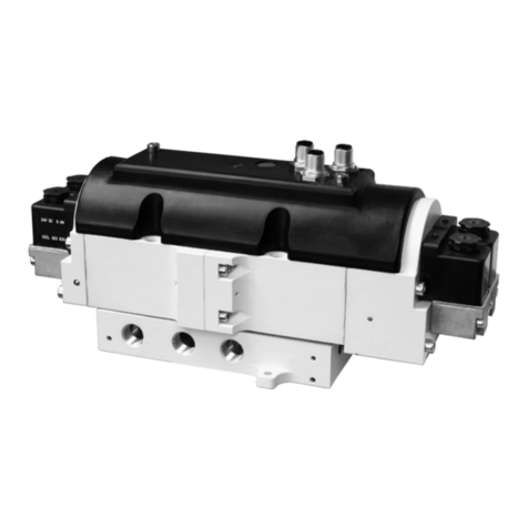
YBYA 31
YC
YD
Manual
Reset
COIL
ACOIL
B
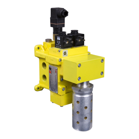
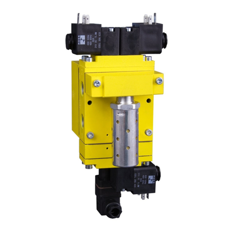
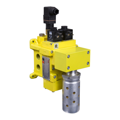
SERPAR®Double Valves
with L-G Monitor, Size 4
Port
Size
Basic
Size
Monitor
Reset
Model Number*CV
Avg. Response Constants Weight
lb (kg)
Right Inlet Left Inlet M F
1-2 2-3 1-2 2-3
3/8 4 Manual 3573D3191** 3573D3195** 3.0 6.0 15 0.70 0.40 8.3 (3.7)
3/8 4 Remote 3573D3192** 3573D3196** 3.0 6.0 15 0.70 0.40 8.3 (3.7)
1/2 4 Manual 3573D4211** 3573D4215** 3.0 8.0 15 0.65 0.35 8.3 (3.7)
1/2 4 Remote 3573D4212** 3573D4216** 3.0 8.0 15 0.65 0.35 8.3 (3.7)
3/4 4 Manual 3573D5211** 3573D5215** 3.0 9.0 15 0.65 0.35 8.3 (3.7)
3/4 4 Remote 3573D5212** 3573D5216** 3.0 9.0 15 0.65 0.35 8.3 (3.7)
* NPT port threads. For BSPP threads, add a “D” prefix to the model number, e.g., D3573D3191W.
** Insert voltage code: “W” = 24 volts DC; “Z” = 110-120 volts AC, 50/60 Hz; e.g., 3573D3191W.
For other voltages consult ROSS.
STANDARD SPECIFICATIONS (for valves on this page):
Construction: Dual poppet.
Mounting Type: Inline.
Pilot Solenoids: Two, rated for continuous duty.
Standard Voltages: 24 volts DC; 110-120 volts AC, 50/60 Hz.
Power Consumption (each solenoid):30 VA inrush, 16 VA holding
on 50 or 60 Hz; 11 watts on DC.
Electrical Connections: Cord-grip connectors at solenoids.
Ambient Temperature: 40° to 120°F (4° to 50°C).
Media Temperature: 40° to 175°F (4° to 80°C).
Flow Media: Filtered air.
Inlet Pressure: 30 to 100 psig (2 to 7 bar).
L-G Reset Pressure: Remote pneumatic reset models require a
pressure of at least 30 psig (2 bar). Manual reset models use internal
valve pressure.
Inlet Port: Models are available with the inlet port on either the right
or the left side of the valve body.
Valve Without Silencer Exhaust port has threaded flange only, consult ROSS.
35 Series
Port Size Basic Size Kit Number
3/8 4 658K77
1/2 4 659K77
3/4 4 660K77
Valve Without Piping Flanges
Port
Size
Basic
Size
Monitor
Reset
Model Number*
Right Inlet Left Inlet
3/8, 1/2,
3/4 4Manual 3573D4241** 3573D4245**
Remote 3573D4242** 3573D4246**
RESET VALVES for L-G MONITOR
On valve models with manual reset a button on the side of the monitor is
pushed to perform the reset function. Models for remote reset, however,
require a small reset valve and the installation of a 1/8 line from the reset
valve to the reset port on the monitor.ROSS offers 3/2 normally closed valves
with either manual or electric control that are suitable for this purpose, valves
size 8, 12, 30 with L-G monitor are suggested.
Reset Valves
Description Model Numbers
Flush Pushbutton: Green 1223B1FPG
Mushroom Button: Green 1223B1MBG
Direct Solenoid Control for Line Mounting 1613B1020**
Direct Solenoid Control for Base Mounting W1413A1409**
(Base: 516B91)
Valve Response Time
The constants above, designated M and
F, can be used to determine the amount
of time required to fill or exhaust a volume
of any size using the formula on the right:
Vlv. Resp.Time (msec)= M + F *V
M = avg. time for parts movement
F = msec. per cubic inch of volume
V = volume in cubic inches
Pressure Switches
(Electrical Lockout Indicator)
G
G2
3
1
2
Normally
Closed
Normally Open
Ground
Common
Pin 1
Common
Pin 3
Not Used
Pin 2
Normally
Closed
Pin 4
Normally Open
DIN Connector Pinout M12 Connector Pinout
* NPT port threads. For BSPP threads, add a “D” prefix to the model number, e.g., D3573D4241W.
** Insert voltage code: “W” = 24 volts DC; “Z” = 110-120 volts AC, 50/60 Hz; e.g., 3573D4241W. For other voltages consult ROSS
Connection Type Model Number*Port Threads
DIN 43650 Form A 586A86 1/8 NPT
M12 Micro-DC 1153A30 1/8 NPT
*
Pressure switch closes on falling pressure of 5 psig (0.34 bar).
