Rothenberger COLLINS CLASSIC 22A User manual

COLLINS CLASSIC 22A
COLLINS CLASSIC 22A
Instructions for use
Instruction d’utilisation
Instrucciones de uso

Overview
A
Automatic Die Head
B
Standard Die Head
I
10
7
11
5
1
3
2
4
6
8
9
4
2
3
1
5
1
2
3
4
5
6
Reaming
D

Intro
ENGLISH page 1
Please read and retain these directions for use. Do not throw
them away! The warranty does not cover damage caused
by incorrect use of the equipment! Subject to technical
modifications!
ESPAÑOL page 35
¡Por favor, lea y conserve el manual de instrucciones! ¡No lo tire!
¡En caso de daños por errores de manejo, la garantía queda sin
validez! Modificaciones técnicas reservadas!
FRANÇAIS page 47
Lire attentivement le mode d’emploi et le ranger à un endroit
sûr! Ne pas le jeter ! La garantie est annulée lors de dommages
dûs à une manipulation erronée ! Sous réserve de modifications
techniques!
EC-DECLARATION OF CONFORMITY
We declare on our sole accountability that this product conforms
to the standards and guidelines stated.
DECLARACION DE CONFORMIDAD CE Declaramos, bajo
nuestra responsabilidad exclusiva, que este producto cumple con
las normas y directivas mencionadas.
DECLARATION CE DE CONFORMITÉ
Nous déclarons sous notre propre responsabilité que ce produit
est conforme aux normes et directives indiquées.
ROTHENBERGER USA – CLASSIC 22A
Phone 800-545-7698 • FAX 815-633-0879 www.rothenberger-usa.com

ORDERING SPARE PARTS
To order Spare Parts, please use the part
numbers provided in this user manual.
ROTHENBERGER USA – CLASSIC 22A
ENGLISH www.rothenberger-usa.com • Phone 800-545-7698 • FAX 815-633-0879

Safety Information.........................................2
Correct use ......................................................2
General safety rules.......................................2
Technical Specifications .................................4
Standard Equipment...................................4
Accessories ..................................................4
Stands...........................................................4
Functions of the thread machine .................5
Overview......................................................5
Functional description................................5
Transporting the thread machine.................5
Operating Procedure......................................6
Electrical connection...................................7
The thread oil ..............................................7
Checking the thread oil..............................7
Setting the amount of thread oil..............7
Threading Pipe or Rod....................................8
Cutting Pipe or Rod.....................................8
Reaming Pipe...............................................8
Installing Die Heads .....................................10
Nipplemax, 1⁄8" – 2" ......................................14
Maintenance and inspection.......................15
Disposal.........................................................16
Repair service................................................18
Diagrams .......................................................18
Wiring Diagrams, STD & R&L 22A / SM2000...........18
Wiring Diagrams, STD 22A / SM2000 / SM4000......19
Standard 22A Main Assembly..................................20
Right and Left 22A Main Assembly.........................22
Standard 22A Spindle Assembly .............................24
Right and Left 22A Spindle Assembly ....................24
Pump and Oil Line Assemblies.................................25
Cutter Assembly #R04200159R...............................26
22A Adjustable Cone Reamer Assembly ................26
Standard 22A Carriage Assembly............................27
Right and Left 22A Carriage Assembly...................27
Oil Spout Assembly...................................................27
Snap-O-Matic Die Head Assemblies 1⁄8" – 2" .......28
Uniquad Die Head Assembly 1⁄8" – 2"...................28
Automatic Die Head Type R 56052..........................29
22A Motor and Gearbox Assembly.........................30
Die Heads ..................................................................31
Preparing for Operation ..........................................32
Spanish Safety ..............................................35
French Safety ................................................47
Maintenance record .....................................61
Thread Sizes and Specifications..................62
Index
Markings in this document
Danger
This sign warns against the danger of personal injuries.
Caution This sign warns against the danger of property
damage and damage to the environment.
Call for action
1
ROTHENBERGER USA – CLASSIC 22A
Phone 800-545-7698 • FAX 815-633-0879 • www.rothenberger-usa.com ENGLISH

Safety Information
Correct use
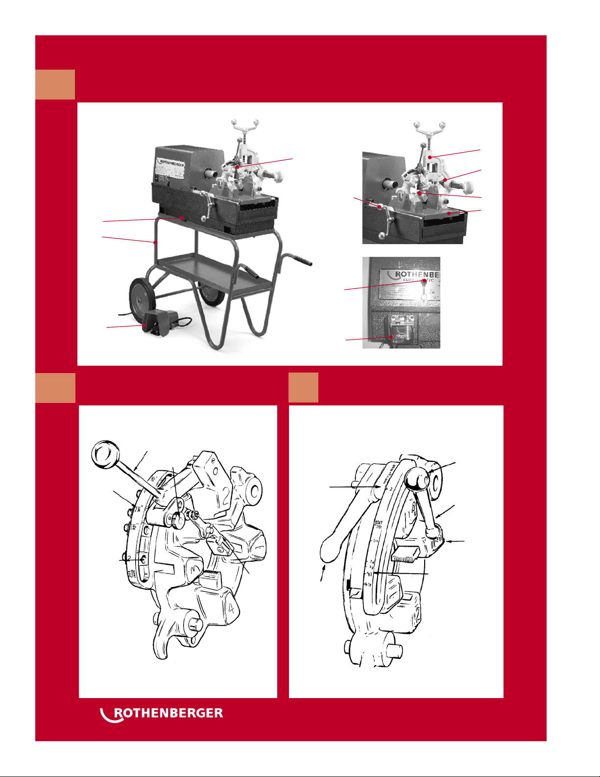
The thread machine COLLINS CLASSIC 22A may only
be used for cutting off and deburring and making
bolt threads as described in “Technical data”.
The COLLINS CLASSIC thread machines may only
be operated with suitable standard and automatic
heads that have been inspected and recommended
by ROTHENBERGER, and with thread jaws as
described in “Technical data”.
The supplied safety pedal carries the GS approval of
the professional liability insurers’ association and is
compulsory for using the machine in Germany.
Never make technical or design modifications to
the thread machine and to the accessory parts. This
would render the operating permit void and would
represent an accident and injury risk.
When using electrical tools and machines, basic
safety measures must be observed and followed in
order to provide protection against electric shock,
injury and fire risks. Read the instructions precisely
before using the machine. Always keep the safety
instructions to hand.
General safety rules
WARNING! Read all instructions. Failure to
follow all instructions listed below may
result
in electric shock, fire and/or serious injury.
SAVE THESE INSTRUCTIONS.
1)
Work area
a)
Keep work area clean and well lit. Cluttered
and dark areas invite accidents.
b)
Do not operate power tools in explosive
atmospheres, such as in the presence of
flammable liquids, gases or dust. Power tools
create sparks which may ignite the dust or
fumes.
c)
Keep children and bystanders away while
operating a power tool. Distractions can cause
you to lose control.
2)
Electrical safety
a)
Power tool plugs must match the outlet.
Never modify the plug in any way. Do not use
any adapter plugs with earthed (grounded)
power tools. Unmodified plugs and matching
outlets will reduce risk of electric shock.
b)
Avoid body contact with earthed or grounded
surfaces such as pipes, radiators, ranges
and refrigerators. There is an increased risk
of electric shock if your body is earthed or
grounded.
c)
Do not expose power tools to rain or wet
conditions. Water entering a power tool will
increase the risk of electric shock and will
damage the tool.
d)
Do not abuse the cord. Never use the cord for
carrying, pulling or unplugging the power
tool. Keep cord away from heat, oil, sharp
edges or moving parts. Damaged or entangled
cords increase the risk of electric shock.
e)
When operating a power tool outdoors, use
an extension cord suitable for outdoor use.
Use of a cord suitable for outdoor use reduces
the risk of electric shock.
3)
Personal safety
a)
Stay alert, watch what you are doing and use
common sense when operating a power tool.
Do not use a power tool while you are tired
or under the influence of drugs, alcohol or
medication. A moment of inattention while
operating power tools may result in serious
personal injury.
b)
Use safety equipment. Always wear eye
protection. Safety equipment such as dust
mask, nonskid safety shoes, hard hat, or
hearing protection used for appropriate
conditions will reduce personal injuries.
c)
Avoid accidental starting. Ensure the switch
is in the off position before plugging in.
Carrying power tools with your finger on the
switch or plugging in power tools that have
the switch on invites accidents.
d)
Remove any adjusting key or wrench before
turning the power tool on. A wrench or a key
left attached to a rotating part of the power
tool may result in personalinjury.
e)
Do not overreach. Keep proper footing and
balance at all times. Thisenables better control
of the power tool in unexpected situations.
f)
Dress properly. Do not wear loose clothing or
jewelery. Keep your hair, clothing and gloves
away from moving parts. Loose clothes,
jewelery or long hair can be caught in moving
parts.
g)
If devices are provided for the connection of
dust extraction and collection facilities, ensure
these are connected and properly used. Use of
these devices can reduce dust related hazards.
4)
Power tool use and care
a)
Do not force the power tool. Use the correct
power tool for your application. The correct
power tool will do the job better and safer at
the rate for which it wasdesigned.
b)
Do not use the power tool if the switch
does not turn it on and off. Any power tool
that cannot be controlled with the switch is
dangerous and must berepaired.
2ROTHENBERGER USA – CLASSIC 22A
ENGLISH www.rothenberger-usa.com • Phone 800-545-7698 • FAX 815-633-0879

c)
Disconnect the plug from the power source
before making any adjustments, changing
accessories, or storing power tools. Such
preventive safety measures reduce the risk of
starting the power tool accidentally.
d)
Store idle power tools out of the reach of
children and do not allow persons unfamiliar
with the power tool or these instructions
to operate the power tool. Power tools are
dangerous in the hands of untrained users.
e)
Maintain power tools. Check for misalignment
or binding of moving parts, breakage of parts
and any other condition that may affect the
power tools operation. If damaged, have
the power tool repaired before use. Many
accidents are caused by poorly maintained
power tools.
f)
Use the power tool, accessories and tool bits
etc., in accordance with these instructions
and in the manner intended for the particular
type of power tool, taking into account
the working conditions and the work to
be performed. Useof the power tool for
operations different from those intended
could result in a hazardous situation.
5)
Service
Have your power tool serviced by a qualified repair
person using only identical replacement parts.
This will ensure that the safety of the power tool is
maintained.
It is essential to read and understand the general
safety instructions!
Never put fingers, your face, hair or other parts
of the body, or loose, wide items of clothing into
the operating and intake areas of rotating parts
(workpiece, clamping chuck, centering chuck). Do
not wear jewelery (rings, chains etc.). Risk of injury
and accidents!
In the event of faults (unusual smell, vibrations,
and unusual noises) during work with the COLLINS
CLASSIC 22A, it is essential to immediately press the
safety pedal and perform an EMERGENCY STOP of
the machine!
If the machine is running, it is prohibited to hold the
workpieces manually or to perform similar work, and
to fit and remove parts such as filters, valves, pipe
sections etc!
Wear safety clothing! Wear a safety mask to provide
protection against splashes of thread oil as well as
any chlorine gas vapors (from thread oil burning on
hot tool and workpiece surfaces)! Wear a safety hat
to cover and protect long hair. Wear safety gloves
when changing the thread jaws, the pipe cutting
wheel and the pipe deburrer. Wear safety gloves
when changing the tool and workpiece. The thread
and thread cutting dies get hot during threading!
Wear safety footwear. Risk of injury from wet,
slippery and possibly off-center machine parts when
changing the tool!
Do not remove metal and plastic chips using
compressed air! There is a risk of eye injuries and loss
of eyesight!
Ensure sufficient ventilation during indoor use
(closed rooms). The permissible ambient temperature
is between 0°C and 40°C / 32º and 104º!
Before changing the cutting heads, the cutting
wheel, the pipe deburrer, always switch off the
machine and disconnect power.
After it has been switched off, the machine still
coasts for a while until it comes to a standstill.
Do not touch any parts before the machine is
completely stationary and the electrical plug has
been pulled out!
In the case of the threaded pipes, carry out a
pressure test in order to ensure that no gas or water
can escape after the pipes are fitted!
3
ROTHENBERGER USA – CLASSIC 22A
Phone 800-545-7698 • FAX 815-633-0879 • www.rothenberger-usa.com ENGLISH

Technical Specifications
Threading Capacity
Pipe ............................................................. 1⁄8" thru 2"
Bolt ............................................................ 1⁄4" thru 21⁄4"
Cutter
Wheel type with sliding roller block
Cutting capacity: Pipe ........................ 1⁄8" thru 2"
Bolt .......................... 1⁄4" thru 1"
Reamer
Adjustable 5-flute cone-type, right-hand
Reaming Capacity: Pipe ............................. 1⁄8" thru 2"
Chuck
High-speed automatic chuck with 8 replaceable and
reversible jaws, 4 in front and 4 in rear.
Oil Pump
Gerotor-type, reversible on right and left machines
Switch, Operating
Single-phase machines: heavy-duty, drum-type,
release-off-thread
Three-phase machines: heavy-duty, rotary-type,
release-off-thread 1, thread 2
Switch, Foot
Heavy-duty, oil and watertight, with safety guard, ON-OFF
Switch, Directional (right & left machine only)
rocker-type, right-off-left
Motor
Single-Phase
a115V AC/DC, 50-60 Hz, 20 amps, . 1/2 HP, 6-brush
universal type
b230V AC/DC, 50-60 Hz, 10 amps,. 1/2 HP, 6-brush
universal type
Three-Phase (optional, available at extra cost)
a230V AC, 50 or 60 Hz, 5.8/4.7 amps, 2/11/2 HP,
3400/1700 rpm, two-speed induction-type
b380/440V, AC, 50 or 60 Hz, 6.1 /3.9 amps, 2.7/2 HP,
2800/1400 rpm, two-speed induction-type
Spindle RPM (free-running)
Standard or right & left single-phase machine:
72 rpm with standard gearbox
54 rpm with optional low speed gearbox
100 rpm with optional high speed gearbox
Right & left three-phase machine:
60 rpm (thread 1), 120 rpm (thread 2)
Noise Level
Single-phase machines: 84 dB max. (“A” scale, slow
response)
Three-phase machines: 81 dB max. (“A” scale, slow
response)
Gearbox
Standard or right & left single-phase machine;
Helical gear construction with 13.1 :1 reduction
(optional low speed gearbox has 16.7:1 and high
speed gearbox has 9.6:1 reduction.)
Right & left three-phase machine:
Helical gear construction with 3.84:1 reduction
Shipping Weight (less die heads)
Single-phase machines: 235 lb.
Three-phase machines: 265 lb.
Standard Equipment
Thread Cutting Oil ....................... 1 gal. Thred-O-Matic Oil
Hex Keys ................................................. 1⁄8", 5⁄32", 3⁄16", 7⁄32",
1⁄4", 5⁄16", 3⁄8", 1⁄2"
Accessories
Grooving/Chamfering Head (No. 12200) ............ 3⁄4" – 2"
Reaming/Chamfering Head (No. 13384) ............. 3⁄4" – 2"
Pipe Support (No. 13894) ............................. for long work
Ball Bearing Pipe Support (No. 13206); and
Pipe Support Fitting.................... using 1" and 11⁄4"pipe,
a stationary pipe stand can be assembled
for extra long work
Baffle Plate (No. 00155)........................mounts in oil sump
to prevent oil spillage
Machine Cover (No. 00154) ......................... durable fitted,
vinyl/canvas cover
Oil Spout Assembly (R04200156R)..........carriage-mounted
flex hose for additional oiling
Stands
No. 00045.......................................................... wheel stand
with tray and 14" rubber tire wheels
No. E-239 ......................................................... wheel stand
with enclosed cabinet,
and 14" rubber tire wheels
4ROTHENBERGER USA – CLASSIC 22A
ENGLISH www.rothenberger-usa.com • Phone 800-545-7698 • FAX 815-633-0879

Functions of the
thread machine
Overview
1 Pipe cutter
2 Thread jaws
3 Internal deburrer
4 Tool carriage
5 Oil drainage screw
6 Feeder hand wheel
7 Foot switch
8 Central lubrication system
9 T.O.R.-switch
10 Die head
11 Stand (optional)
Functional description
Threads are cut or turned on workpieces such
as pipes or rods in the thread machine COLLINS
CLASSIC 22A.
The machine consists of:
-a drive motor that rotates both clamping
chucks
-a automatic double clamping chuck for
securing the workpiece
-a pipe cutter for cutting the workpiece to
length
-an internal deburrer
-a die head for making a thread on the
workpiece
-an oil pump that lubricates and cools with
thread oil
-a tool carriage guided on both sides with a
toothed feed
-a chip collecting and oil trough
-a safety pedal
-a coasting restrictor
Transporting the
thread machine
Bend at the knees when lifting the machine
so as to protect your back against over-
stressing.
Fix the tool carriage so that it cannot move
while the machine is being transported. Hold the
machine securely by its base to lift it. Do not hold
the machine by its centering chuck or the internal
deburrer when carrying it!
If the machine is transported with the thread oil
still inside, the oil might splash out onto clothing
due to vibrations!
Thread oil on the surface of the machine makes it
slippery. Ensure that it does not slip out of your
hands when you lift it!
5
ROTHENBERGER USA – CLASSIC 22A
Phone 800-545-7698 • FAX 815-633-0879 • www.rothenberger-usa.com ENGLISH

WARNING
Operator should be thoroughly familiar
with preceding Safety Precautions before
attempting to operate this equipment.
1. Mount machine on a stand or bench as instructed.
2. Pour one gallon of Thred-O-Matic oil into the oil
sump. Thred-O-Matic oil is a special oil designed
to stand up under the high speed operation of
this machine. Other oils will have a tendency
to break down, causing excessive die wear and
poor thread quality. If Thred-O-Matic oil is not
available, use a high quality equivalent dark,
sulphur-base thread cutting oil. Oil pump is self-
priming; therefore no priming is needed.
3.
For first 10 days of operation, lubricate the spindle
bearings every 4 hours with SAE 30 lubricating oil.
4. Your COLLINS 22A is equipped with two electrical
switches; a safety foot switch, and a
THREAD/OFF/RELEASE (T.O.R.) switch . COLLINS
right- and left-hand 22As have a third switch; a
right- and left-hand directional switch. The func-
tion of these switches are as follows: The safety
foot switch is designed to provide the operator
with a rapid method of stopping electrical power
to the machine if an emergency should occur.
Also, it insures that the machine cannot be oper-
ated unless the operator is in proper position.
The THREAD/OFF/RELEASE switch is the main
operating switch. The THREAD position closes the
jaws and rotates the spindle. The OFF position
stops the machine. The REVERSE position opens
the jaws. The REVERSE position is spring-loaded
to return to the OFF position. The right- and left
hand switch changes the direction of the motor
and therefore the direction of the spindle.
5. After making proper electrical connection, step
on foot switch and move the THREAD/OFF/
RELEASE switch to THREAD position in order to
check oil flow. When die head is in the down
position, oil will flow through the die head. If up,
oil will flow from bypass pressure relief valve.
Operating Procedure
Figure 5
COLLINS CLASSIC 22A
6ROTHENBERGER USA – CLASSIC 22A
ENGLISH www.rothenberger-usa.com • Phone 800-545-7698 • FAX 815-633-0879

Electrical connection
Do not place either the machine or workpieces
on the connecting cable, otherwise the cable
could be damaged and electrical current could be
exposed, presenting an electric shock hazard!
Never touch the plug or cable with wet hands.
Electric shock hazard!
When connecting the machine to the electricity
supply, always ensure that the switch is set
to “OFF” ”, otherwise there is a risk that the
machine will start up unnoticed and unsupervised
when the power is connected!
It is essential that the voltage on the machine’s
rating plate corresponds to the power source,
otherwise the machine could get hot, smoke
could develop, start a fire and cause damage!
The integrated overload protection automatically
stops the machine in the event of an overload
or power fluctuations! Switching back on is not
possible until one minute has elapsed!
The thread oil
For use ROTHENBERGER high-performance no.
ROCOOL® CUTTING OIL # 01922.
This oil is not suitable for drinking water pipes!
Keep thread oils out of the
reach of children!
Do not thin thread oil or mix it with other oils!
If the thread oil becomes mixed with water, it
turns milky-white, its quality is reduced and the
tapped thread displays lower quality. It is then
recommended to change the oil!
Avoid direct sunlight and store the oil in a dark
place!
Close the oil container tight after use in order to
prevent the ingress of dirt and water!
ATTENTION PERSONS WITH ALLERGIES!
Thread oil that lands on the skin can cause
skin irritation, inflammation and allergic
reactions! When handling oil, wear protective
clothing and cover exposed skin areas. If
your skin comes into contact with oil, wash
it immediately with tap water and soap. If
thread oil burns onto hot workpiece or tool
surfaces, this can produce toxic vapors or gases
(e.g. chlorine gas when red oil burns). If you
have accidentally inhaled this oil mist or oil
vapors, go out into the fresh air immediately
and consult a doctor without delay!
Checking the thread oil
A new machine or a machine that has not been
used for an extended period is covered with an
oil film to protect it. Remove this with a clean
cloth.
On the right side of the machine, fill up with the
supplied thread oil (3-4l / 1 gallon).
Ensure that the machine is still switched off and
insert the plug back into the socket.
Switch on the machine and ensure that the thread
oil runs out of the thread head to the cutting
jaws. If the right amount of oil is not supplied,
regulate it with the oil adjustment screw.
Setting the amount of supplied
thread oil
When cleaning, servicing, inspecting or
repairing the machine, it is essential to switch
it off and unplug.
Ensure that the oil tank is filled with oil.
If the amount of thread oil running to the die
head does not meet the requirements, the
supplied amount CAN be
adjusted at the oil pump (1) by
the oil adjustment screw (3).
Undo the locking nut (2) of the
oil adjustment screw.
Turning the oil adjustment
screw clockwise increases
the amount of oil delivered
and turning it anti-clockwise
reduces the amount.
Tighten the locking nut firmly after making the
adjustment.
1
2
3
7
ROTHENBERGER USA – CLASSIC 22A
Phone 800-545-7698 • FAX 815-633-0879 • www.rothenberger-usa.com ENGLISH

Threading Pipe or Rod
Standard 22A
1. Step on foot switch. While operating the machine,
the foot switch will be depressed, providing
power to the machine. If an emergency occurs,
remove foot from switch.
2. Turn T.O.R. switch to RELEASE to open jaws.
4. Release T.O.R. switch, and it will return to OFF
position.
5. Swing die head, cutter; and reamer up and back
to out-of-way position.
6. Insert material into chuck from either front or rear
position for desired length to be cut.
Note: For long pieces of pipe or rod, use No. 10640
Superjack Pipe Stand.
7. Move T.O.R. switch to THREAD position. (Pipe will
be chucked automatically and will rotate.)
Right and Left 22A
1. Turn T.O.R. switch to RELEASE to open jaws.
2. Push directional switch to desired type of thread
(right-hand or left-hand).
Note: Make sure there is no pipe in the machine
before proceeding to Step 3.
3. Again, turn T.O.R. switch to RELEASE position and
jaws will cycle to OPEN position.
4. Insert pipe or rod into chuck from either front or
rear and position for desired length to be cut.
5. Move T.O.R. switch to THREAD position.
6. To reposition for opposite threading direction,
follow Steps 1-5.
Note: Machine must be at a full stop before using
left and right Directional Switch.
Threading Pipe or Rod (Right-hand)
1. Slip the proper size die head onto the carriage
pin, and lower the head into the carriage groove.
2. On Uniquad heads, close operating handle; on
Snap-O-Matic heads, select the correct size and
engage the operating handle pin. On Automatic
die heads, pull operating lever forward to cock
spring-loaded plunger.
3. Turn carriage handle counterclockwise to bring
dies against stock.
4. With T.O.R. switch in THREAD position, and the
safety footswitch depressed, apply slight pressure
on carriage handle until a few threads have been
cut, after which the head will feed itself auto-
matically.
5. Correct thread length is normally obtained when
stock reaches the outside edge of dies. When pipe
is still rotating, open head.
CAUTION
While threading, open die head before carriage
reaches full length of travel. If carriage strikes
base, excessive strain is put on the machine and
damage may result.
6. Move T.O.R. switch to OFF position and turn
carriage handle clockwise to clear the die head
from the pipe.
Threading Pipe or Rod (Left-hand)
Note: Left-hand threading operation possible only
on 22A with right- and left-hand option.
1. Reverse chuck jaws for left-hand threading.
(Follow Steps 1-5 under "Right and Left 22A".)
2. Install left-hand dies into die head. (See "Installing
Dies.")
3. Slip the proper size die head onto the carriage pin,
and lower the head into the carriage groove.
4. Slide die head retainer pin through opening in
carriage to hold die head.
5. Follow right-hand threading instructions, Steps 1-6.
Cutting Pipe or Rod
1. With pipe properly chucked and with cutter,
reamer and die head in out-of-the-way position,
operate carriage handle until cutter is over area
of pipe to be cut.
2. Move T.O.R. switch to THREAD and depress safety
switch.
3. With roller block retracted to fit over pipe or rod,
bring cutter down and turn cutter handle (Fig. 7)
clockwise to force cutter wheel against stock to
make cut.
Note: This machine will cut 1⁄8" through 2" pipe or
¼" through 2¼" rod. NEVER cut into threads,
as this may cause damage to cutter wheel.
4. When pipe is cut, move T.O.R. switch to OFF and
raise cutter to out-of-way position.
Removing Pipe from Chuck
1. Put T.O.R. switch in RELEASE position to open jaws.
2. Release T.O.R. switch; it will return to OFF position.
3. Pull pipe from either front or rear of machine.
8ROTHENBERGER USA – CLASSIC 22A
ENGLISH www.rothenberger-usa.com • Phone 800-545-7698 • FAX 815-633-0879

Reaming the workpieces
The cutting tip of the internal deburrer is very
sharp! Do not touch it with bare hands! Risk
of cutting and injury!
2
3
1
4
6
Swing reamer holder down (1) and insert a pipe
if there is not already one in the machine before
separation.
Raise cutter and die head (4).
Reamer can be extended toward to pipe, if
necessary, by sliding reamer knob (2) toward
reamer arm until contact with reamer holder. Twist
reamer knob to left ¼ turn to lock in position.
With pipe chucked and rotating, turn carriage
handle (6) counter clockwise so that flutes of
reamer enter pipe.
Momentarily apply pressure to handle to force
reamer against pipe to remove burrs.
After reaming, retract reamer (3) and turn T.O.R.-
switch to off. Place reamer in out of way position.
Removing and installing the thread
jaws from and in the die head
Wear gloves in order to prevent cut injuries to
the hands caused by the thread jaws!
After changing the thread jaws, check that they are
secure!
After changing the die head or replacing the thread
jaws, check that they are locked securely in the tool
carriage!
Precise thread is only possible if the number on the
slot of the die head corresponds with the number on
the thread jaw!
Draining off the oil
It is essential to also observe the safety
and disposal regulations in Chapter 7!
Oil drainage screw
9
ROTHENBERGER USA – CLASSIC 22A
Phone 800-545-7698 • FAX 815-633-0879 • www.rothenberger-usa.com ENGLISH

Installing Dies in Uniquad Die Head
(R.H. & L.H.)
The Uniquad Die Head (Fig. 9) requires a set of four
dies to thread pipe ranging from 1⁄8" through 2".
One set of dies is required for each of the following
pipe size ranges: (1⁄8"), (1⁄4" and 3⁄8"), (1⁄2" and 3⁄4"), and
(1" through 2"). Bolt threading requires a separate
set of dies for each bolt size.
1. Lay die head on bench with numbers facing up.
2. Flip operating lever to OPEN position.
Figure 9
Uniquad Die Head
3. Loosen locking lever approximately three turns.
4. Slide operating lever all the way to end of slot in
the OVER direction indicated on size selection bar.
5. Remove dies from die head.
6. Die numbers 1 through 4 must agree with those
on die head.
7. Insert dies until die pins are seated in scroll slots.
8. Slide operating lever until index line on link is
aligned with proper size mark on size selection bar.
9. Tighten locking lever. For bolt threads, align index
line with BOLT line, 1½" on size selection bar.
10. If oversize or undersize threads are required, set
the index line in direction of OVER or UNDER size
mark on size selection bar.
11. To install die head, slip die head onto carriage die
head pin.
Installing Dies in Snap-O-Matic
Die Heads (R.H. & L.H.)
The Snap-O-Matic Die Heads (Fig. 10) are available in
the following models and sizes:
Mono..........................................................................1⁄8"
Dual................................................. (1⁄4" - 3⁄8"), (1⁄2" - 3⁄4")
(1" -11⁄4"), (11⁄2" - 2")
Quad ............................................................... (1" - 2")
One set of dies are required for each of the pipe
size ranges shown above. Bolt threading requires a
separate set of dies for each bolt size.
1. Lay die head on bench with numbers facing up.
2. Remove stop screw with 3/15 hex key.
3. Flip operating lever to OPEN position.
4. Rotate scroll plate with operating lever clockwise
until slots in scroll plate and head line up.
5. Remove dies from die head.
Figure 10
Snap-O-Matic Die Head
6. Die numbers 1 through 4 must agree with those
on die head.
7. Insert dies until die pins are seated in scroll slots.
8. Rotate scroll plate with operating lever towards
selector plates, and replace stop screw.
9. For bolt threads, engage operating lever pin in
selector plate slot marked selector “11⁄2/ BOLT.”
10. If oversize or undersize threads are required, use
5⁄32" hex key to loosen selector plate screws. Slide
10 ROTHENBERGER USA – CLASSIC 22A
ENGLISH www.rothenberger-usa.com • Phone 800-545-7698 • FAX 815-633-0879

selector plate in direction of over or under size
mark on plate. Tighten selector plate screws.
11. To install die head, slip die head onto carriage die
head pin.
Threads
If there is a dangerous situation, release foot from
pedal. This stops the machine.
To restart the machine, press the release button on
the side of the safety pedal.
To guarantee precisely ground threads, follow the
instructions below:
Use only raw material that is in perfect condition
for threads.
If you use deformed and / or pipes cut off at
an angle, it is not possible to cut threads that
conform to the relevant standards!
Use the thread head and the corresponding
thread jaws that matches the thread size! Secure
the thread head correctly on the tool carriage.
Do not place the die head directly and
unprotected on the floor and handle it with care!
Ensure that the thread oil runs on the dies!
Installing Dies in Automatic Opening
Die Head (R.H. & L.H.)
The Automatic Die Head (Fig. 11) requires two sets of
dies to thread pipe ranging from
1⁄2
" through 2". One
set of dies is required for each of the following pipe size
ranges:(
1⁄2
"
and
3⁄4
") and (1" through 2"). Bolt threading
requires a separate set of dies for each bolt size.
Figure 11
Automatic Die Head
1. Make sure trigger assembly is released.
2. Disengage selector pin and swing it up, out of the
way.
3. Lay head down with numbers up.
4. Rotate selector size bar to OPEN position.
5. Remove die segments Nos. 1, 3 and 4. Move die
segment No. 2 until die pin can freely travel in
outer scroll slot.
6. Rotate selector size bar counterclockwise until
No. 2 die segment pin is free and can be removed
from die head.
7. Die numbers 1 through 4 must agree with those
on die head.
8. Slide No. 2 die segment in die head slot as far as
possible. Rotate selector size bar clockwise until it
stops. Push segment 2 into the die head as far as
possible.
11
ROTHENBERGER USA – CLASSIC 22A
Phone 800-545-7698 • FAX 815-633-0879 • www.rothenberger-usa.com ENGLISH

9. Insert segments 1, 3 and 4.
10. Rotate selector size bar counterclockwise and
engage selector pin.
11. For bolt threads, engage selector pin in 1
1⁄2
"
setting.
12. If oversize or undersize threads are required, use
3⁄16
" or
5⁄32
"
hex key
and loosen adjustable selector
screws approximately two turns. Move adjustable
selector in direction of over or under size mark on
selector size bar. Tighten screw.
Note: Factory setting marked on the right-hand
edge of the adjustable Selector.
Threading with Automatic Opening
Die Head (R.H. & L.H.)
Note: Two different thread length gauges are used
on the trigger for NPT (#12693) and BSPT
(#12554).
CAUTION
Do NOT lean over automatic opening die head,
as opening lever could strike face when auto-
matically opening.
1. Install the die head on carriage pin.
2. Find the correct adjustable size selector and
engage the selector pin.
3. Pull operating lever forward to cock the spring
loaded plunger.
4. Insert stock through the spindle from either the
front or rear of the machine.
5. After stepping on foot switch, turn T.O.R. switch
to THREAD.
6. Apply slight pressure on carriage handle until a
few threads have been cut, after which the head
will automatically feed itself.
7. When the correct thread length is obtained, the
die head will open automatically, at which time,
move carriage away from stock.
8. Move T.O.R. switch to OFF.
Continuous threading
1. Remove thread length gauge from the trigger.
2. Lift the trigger set screw out of its socket and rotate
the trigger 45° to get it out of the way.
3. Follow Steps 2 - 6 of THREAD CUTTING (see page 8).
4. When the correct thread length is obtained, open
die head by moving operating lever toward the rear
and move carriage away from the stock.
5. Move T.O.R. switch to OFF.
Figure 12
Die Head #12200
12 ROTHENBERGER USA – CLASSIC 22A
ENGLISH www.rothenberger-usa.com • Phone 800-545-7698 • FAX 815-633-0879

Installing Centering Dies in Die Head
#12200
The 12200 die head uses three centering die segments.
Refer to Die Tables Nos. 8 and 10 for correct centering
dies.
1. Lay die head on bench with numbers facing up.
2. Remove stop screw with 3⁄16" hex key.
3. Rotate scroll plate with operating lever to OPEN
position.
4. Remove dies from die head.
5. Die numbers 2 through 4 must agree with those
on die head.
6. Insert dies until die pins are seated in scroll slots.
7. Rotate scroll plate with operating lever towards
selector plates and replace stop screw.
8. If oversize or undersize adjustment is required,
use 5⁄32" hex key to loosen selector plate screws.
Slide selector plate in direction of over or under
size mark on plate. Tighten selector plate screws.
Installing Tool Bits in Die Head #12200
All tool bits are used in the No. 1 die slot opening on
the 12200 die head. Refer to Die Tables Nos. 8 and 10
for correct tool bit.
1. Mount head on carriage pin.
2. Insert tool bit into the No. 1 die slot opening on
No. 12200 die head.
3. Rotate feed screw handle counterclockwise
slowly until tool bit engages. Continue to rotate
until handle stops.
4. To replace tool bit rotate feed screw handle
clockwise until tool bit disengages. Pull tool bit
out of die head slot.
Operating Die Head #12200 for
Grooving, Beveling, or Saran Cutting
Note:
A. Always retract Tool Bit before operating
machine.
B. Ensure adequate COLLINS oil is present during
machining.
1. Install head on carriage pin.
2. Turn feed screw handle all the way counter-
clockwise until it stops.
3. Disengage operating lever from selector plate
and push it back against the scroll plate stop to
retract centering dies.
4. Make certain the pipe end to be machined is
positioned close to the front jaws.
5. Chuck pipe in the machine as previously
instructed and position die head over pipe by
using carriage feed handle.
6. Pull operating lever towards the operator in
order to engage in proper size slot of selector
plate.
7. Feed the tool bit in the same manner that you
would operate a lathe. Use a slow, even feed
rate.
Note: Do not plunge tool into pipe.
A continuous chip will curl off and away from
the tool at the proper feed. Excessive feed causes
breakdown of the cutting edge which will decrease
tool life or damage the tool.
Excessive feed is indicated by:
a) Poor surface finish
b) Bluish-colored chip due to excessive heat
generation
c) Chips crowd and build up on the tip of the tool,
instead of spiraling off away from the tool.
Advance the tool slowly as the tool breaks through
the pipe. Let the pipe turn 2-3 revolutions when it
breaks through, in order to obtain a clean cut-off
and to avoid tool breakage. After cut-off, advance
the tool until the groove depth indicator size mark
matches the guide line. Turn the feed screw one
turn clockwise to finish the groove to the correct
diameter. Let the pipe rotate 2-3 revolutions to clean
up the groove.
8. Retract tool bit by turning the feed screw han-
dle counterclockwise until it stops. Retract the
centering dies by disengaging and moving the
operating lever away from the operator until it
stops. Move carriage away from pipe and stop
machine.
9. For grooving, check groove diameter.
13
ROTHENBERGER USA – CLASSIC 22A
Phone 800-545-7698 • FAX 815-633-0879 • www.rothenberger-usa.com ENGLISH

Nipplemax, 1⁄8" – 2"
Threading Nipples
1. Ream the inside of the pipe and thread one end
with threading machine.
2. Cut the pipe to required length.
3. Chuck the Nipplemax in the front chuck, being
careful to mount it centered.
4. Put the already-threaded end of the pipe on the
Nipplemax.
5. IMPORTANT: Press the die head with dies
against the pipe firmly, BEFORE switching on the
machine.
6. After the thread is completed, the nipple can be
easily removed by hand.
Notes:
A. The pipe end which will be put on the
Nipplemax should be reamed to remove all I.D.
burrs.
B. The nipple should be put completely on the
Nipplemax.
C. Jaws slots and grooves should be kept clean.
D. Do not start machine until dies contact the
nipple, to avoid slipping.
How to Replace Jaws in Nipplemax:
(see close-up view)
1. Pull down sleeve.
2. Remove retainer (b) from body with a screwdriver.
Don't distort wire.
3. Pull up sleeve to remove it from body.
4. Remove jaws from inside of sleeve and remove
ring to clean slots.
5. Clean jaws, grooves and slots.
6. Put in new jaws.
7. Put sleeve with jaws on body. If it was necessary to
remove ring (a) to clean slots, put ring (a) on body.
Part No. Description
00089 Nipple Max Kit, 1⁄2"-2", with Extension Bar
00190 1⁄2" Chuck
00191 3⁄4" Chuck
00192 1" Chuck
00193 11⁄4" Chuck
00194 11⁄2" Chuck
00195 2" Chuck
00199 Shank, for Nipple Max Chucks
For the standard thread head:
Lower the thread head and move the opening and
closing lever down towards you.
Turn T.O.R.-switch to “thread” and switch on the
machine with the pedal, turn the rotary handle
clockwise so that the thread jaws press on the
workpiece.
Release the rotary handle when two to three
threads have been cut.
With the machine running, slowly move the
opening and closing lever up when the required
number of threads has been cut, so as to end the
cutting process by slowly opening the thread jaws.
If the thread jaws are opened carelessly, steps can
be created in the last section of the thread, with the
result that the thread is faulty!
While threading, open die head before carriage
reaches full length of travel. If carriage strikes base,
excessive strain is put on the machine and damage
may result!
For the automatic thread head:
Two different thread length gauges are used on the
trigger for NPT and BSPT.
Do not lean over automatic opening die head as
opening lever could strike face when automatically
opened!
Install the die head on carriage pin and adjust the
proper size. Pull operating lever forward to cock
the spring loaded plunger.
Turn T.O.R.-switch to “thread” and switch on the
machine with the pedal, turn the rotary handle
counter-clockwise so that the thread jaws press
onto the workpiece.
14 ROTHENBERGER USA – CLASSIC 22A
ENGLISH www.rothenberger-usa.com • Phone 800-545-7698 • FAX 815-633-0879

Release the rotary handle when 2 to 3 thread
turns are cut.
The thread jaws open automatically via a
longitudinal stop lever when the thread has been
fully cut.
Switch off the machine by taking your foot off the
safety pedal and turn T.O.R.-switch to “off”.
Removing the workpiece
The workpiece is damp and slippery from the
thread oil. Carefully ensure that it does not
slip out of your hands and drop onto your
feet when you remove it from the machine!
Turn the feeder hand wheel clockwise and move
back the tool carriage. Release the clamping
chuck.
Release the centering chuck and pull out the
workpiece.
Cleaning after use
Do not remove metal and plastic chips using
compressed air!
There is a risk of eye injuries and loss of
eyesight!
Do not pick up sharp-edged metal chips
with your bare hands! Risk of injury! Wear
protective gloves!
Remove chips from on and around the machine.
Use a wire brush to remove chips from and clean the
clamping chuck, the thread jaws of the thread head
and the internal deburrer.
Use a cloth to wipe thread oil splashes from the
machine and the workplace.
Maintenance and
inspection
All machines are subject to natural wear during use.
They must be maintained from time to time and
wear parts must be replaced.
This work may only be carried out by an authorized
ROTHENBERGER service center. This gives you a full
warranty on the material and workmanship!
If the machine is being cleaned, maintained,
inspected or repaired, it is essential to switch it off
and to unplug!
Always avoid uncontrolled starting-up of the
machine. Risk of injury and accidents!
Threading oil maintenance:
Change threading oil every 40 hours of use or
when threading oil has become contaminated or
dirty.
To drain oil, position a container under drain plug
and remove plug.
When oil has drained out use a rag to clean oil
sump of chips and sediment. Remove all debris
around oil filter.
Replace drain plug and pour (3-4l / 1 gallon) of
ROTHENBERGER-oil into oil sump.
Carriage rails and gear:
Keep clean and oil frequently with machine oil.
Ring gear:
Remove spindle cover and check ring gear every
six months to see if additional high temperature
graphite gear lubricant needs to be applied.
Motor:
Check motor for brush wear every six months. If
motor lacks power due to a dirty commutator, use
a commutator cleaner stick or fine emery cloth.
Lubrication is not required as all motors have sealed
ball bearings.
Gear case:
It is permanently lubricated and requires no
maintenance
Brake band:
If slippage of stock should occur after wire brushing
jaws, then:
Stop the machine.
Remove spindle cover.
Tighten brake adjustment bolt. Start machine.
Turn switch “OFF” and spindle should coast one
revolution. If not, repeat steps.
Replace spindle cover.
Thread jaws:
Keep sharp and free of chips at all times. For
15
ROTHENBERGER USA – CLASSIC 22A
Phone 800-545-7698 • FAX 815-633-0879 • www.rothenberger-usa.com ENGLISH

sharpening service please contact our customer
service.
Central lubricating system
Proper lubrication of the spindle bearings and brake
band is essential for trouble-free operation and long
life for the machine. The central lubricating system
makes this a very easy procedure.
Check the reservoir and refill if necessary with SAE 30
weight lubricating oil into inlet.
Once a day, before starting the machine for the first
time, lift and release the lubricator plunger six times.
During normal operation, lift and release the plunger
four times every two hours of operation.
Replace filter element once a year on the central
lubricator pump.
inlet plunger
filter element
Changing the jaws
Keep clean with wire bush to avoid slippage. To
replace jaws: Unplug machine
Remove spindle cover
Remove jaw retaining rings and slide jaws off
shaft
If machine has been used for only right hand
threading, reverse jaws and remount on jaw shafts so
that the unused side faces spindle opening.
Inspect jaw shaft keys for wear.
Install replacement jaws so that single row jaws
(1) are the opposite of each other and doubles (2)
are opposite each other. Also alternate single and
double jaws between front (3) and rear chucks (4).
1
2
3
4
Daily inspection
Attention! Before starting the lubrication-
works the power plug has to be
taken out of
the power source.
Check the plug, cable and extension cable to
ensure they are undamaged.
Correctly filled oil trough
Adjust the oil screw if necessary
Clean the oil tank if there are impurities in it.
Inspect the thread jaws, pipe cutter and internal
deburrer for any wear and replace parts if there is
wear.
Clean the clamping jaws with a wire brush if they
are dirty.
Check that the dowel screws are secure. Tighten if
necessary.
Remove dirt and chips from the machine regularly.
Apply anti-rust grease if the machine is not going
to be used for an extended period.
Check the central lubricating system
Disposal
Metal, electrical and electronic parts
Parts of the unit are valuable materials and can be
recycled. Approved and certified recycling companies
exist for this purpose. Metals must be sorted and
delivered separately to a disposal company.
Please consult your responsible refuse disposal
authority for how to dispose of unusable parts in
an environmentally responsible way (e.g. electronic
scrap):
For EU countries only:
Do not dispose of electric tools with
domestic waste. In accordance with
European Directive 2002/96/EC on waste
electrical and electronic equipment and its
implementation as national law, electric
tools that are no longer serviceable must
be collected separately and utilized for
environmentally compatible recycling.
Oils and lubricants
Only specialist companies are authorized to dispose
of old oils.
Old oils and contaminated oils must be stored and
disposed of in sealed, oil-resistant containers (metal
drums).
Defective electrical appliances and machines that
16 ROTHENBERGER USA – CLASSIC 22A
ENGLISH www.rothenberger-usa.com • Phone 800-545-7698 • FAX 815-633-0879
Table of contents
Other Rothenberger Tools manuals

Rothenberger
Rothenberger 5.6271 User manual

Rothenberger
Rothenberger ROWELD ROFUSE Sani 160 User manual

Rothenberger
Rothenberger ROFROST Turbo R290 28 UK User manual

Rothenberger
Rothenberger ROMAX Compact TT User manual

Rothenberger
Rothenberger 6.2200 User manual

Rothenberger
Rothenberger 2224.04 User manual

Rothenberger
Rothenberger ROMAX AC ECO User manual

Rothenberger
Rothenberger Rogroover User manual

Rothenberger
Rothenberger SIEVERT PRO 9 User manual

Rothenberger
Rothenberger Ro-Groover 1-12 User manual