RST meteoscan 938PRO User manual

professional wireless
multiple- hannel weather station
meteoscan 938PRO
RST01938
Operation Manual
GB
www.barometer.ru
RST01938Manual 20.10.2017 13:20 Страница 1

page 2 RST01937 meteostanciya
RST01938Manual 20.10.2017 13:20 Страница 2

RST01937 meteostanciya page 3
verview
1. Inventory of contents
QTY Item
1 Display Console Frame Dimensions (LxHxW): 11.5 x 8.2 x 4 m
LCD Dimensions (LxW): 9.5 x 5.5 m
3 Thermo-hygrometer transmitter (WH31)
Dimensions (LxHxW): 12 x 4 x 1.8 m
1 USB Cable for PC Conne tion
1 Adaptor
Console
Sensors
RST01918 RST01919
RST01938Manual 20.10.2017 13:20 Страница 3

page 4 RST01937 meteostanciya
2. Introduction
Thank you for your purchase this professional weather station. This device can receive signals up
to at most 8 sensors. All the sensors measure temperature, humidity, heat index and dew point
and transmit to the console and displayed in defined channels.
This manual will guide you step-by-step through setting up your device. Use this manual to be-
come familiar with your professional weather station, and save it for future reference.
3. Getting Started
Note: The power up sequence is performed in the order shown in this section(insert batteries in
the display console first, remote transmitters second). 3.1 Display Console Set Up Connect the
console to AC power with the included AC adapter.
3.1 Display Console Set Up
Connect the console to AC power with the included AC adapter.
f the remotes do not update, please reference the troubleshooting guide in Section 0.
3.2 Thermo-Hygrometer Sensor Set Up
Note: To avoid operating problems, please take note of battery polarity before/when inserting
any Alkaline Batteries (permanent damaged could be introduced by inserting the battery in
wrong direction). Do not use rechargeable batteries. We recommend fresh alkaline batteries for
outdoor temperature range between -20℃and 60℃and fresh lithium batteries for outdoor tem-
perature range between -40℃and 60℃.
1. Move the transmitters(s) about 5 to 10’ away from the display console (if the transmitters are
too close, they may not be received by the display console). With multiple transmitters, make
sure all transmitters are powered up and displaying different channels on the display.
2. Remove the battery door on the back of the thermo-hygrometer sensor by sliding down the
battery door, as shown in Figure 4.
Figure 4.
RST01938Manual 20.10.2017 13:20 Страница 4

RST01937 meteostanciya page 5
3. BEFORE inserting the batteries, locate the dip switches on the inside cover of the lid of the trans-
mitter.
4. Channel Number: the weather station support up to eight sensors, and includes three trans-
mitters. To set each channel number, change Dip Switches 1,2,3 as referenced in Figure 6.
5. Temperature unit of Measure: To change the sensor display units of measure (Foor Co) change
Dip Switch 4, as referenced in Figure 5.
Pull down the button: Pull up the button:
6. nsert two AA batteries
7. Wait for seconds until temperature and humidity displayed on the LCD screen of sensors.
8. Verify the correct channel number (CH) and temperature units of measure are on the display,
as shown in Figure 6.
(1) Temperature
(2) Temperature units ((℉or ℃)
(3) Channel number
(4) Relative humidity
9. Close the battery door.
10. Repeat for the additional remote sensor, verifying
each remote is on a different channel.
Figure 5.
Figure 6
RST01938Manual 20.10.2017 13:20 Страница 5

page 6 RST01937 meteostanciya
3.3 Sensor peration Verification
Verify the humidity sensors match closely with all of the sensors in the same location (about 5 to
10’ apart). The sensors should agree within 10% (the accuracy is ± 5%). Allow about 30 minutes
for all sensors to stabilize. The humidity can be adjusted or calibrated later to match each other
a known source.
Verify the temperature sensors match closely with all of the sensors in the same location (about
5 to 10’ apart). The sensors should be within 2°C (the accuracy is ± 1°C). Allow about 30 minutes
for all sensors to stabilize. The temperature can be adjusted or calibrated later to match each
other or a known source.
3.4 Radio Controlled Clock (RCC)
After the remote sensor is powered up, the sensor will transmit weather data for 30 seconds, and
then the sensor will begin radio controlled clock (RCC) reception. During the RCC time reception
period (maximum 5 minutes), no weather data will be transmitted to avoid interference. Once
the radio controlled time is received the RCC signal received successfully, the RCC reception
icon will turn on in the outdoor sensor LCD display. Then outdoor sensor sends the RCC signal
to display console, Once the radio controlled time is received, RCC reception icon will turn
on in the display console. (reference Figure 10).
f the signal reception is not successful within 3 minute, the signal search will be cancelled and
will automatically resume every six hours until the signal is successfully captured. The regular RF
link will resume once RCC reception routine is finished. n some locations, RCC reception may
take a couple of days to receive the signal.
4. Remote Sensor Installation
Before mount the units, ensuring that the receiver can still pick up the signal from transmitters. t is
recommended to mount the sensors on a north facing wall, in a shaded area. Direct sunlight and
radiant heat sources will result in inaccurate temperature readings. Although the sensors are
water resistant, it is best to mount in a well protected area, such as under an eve.
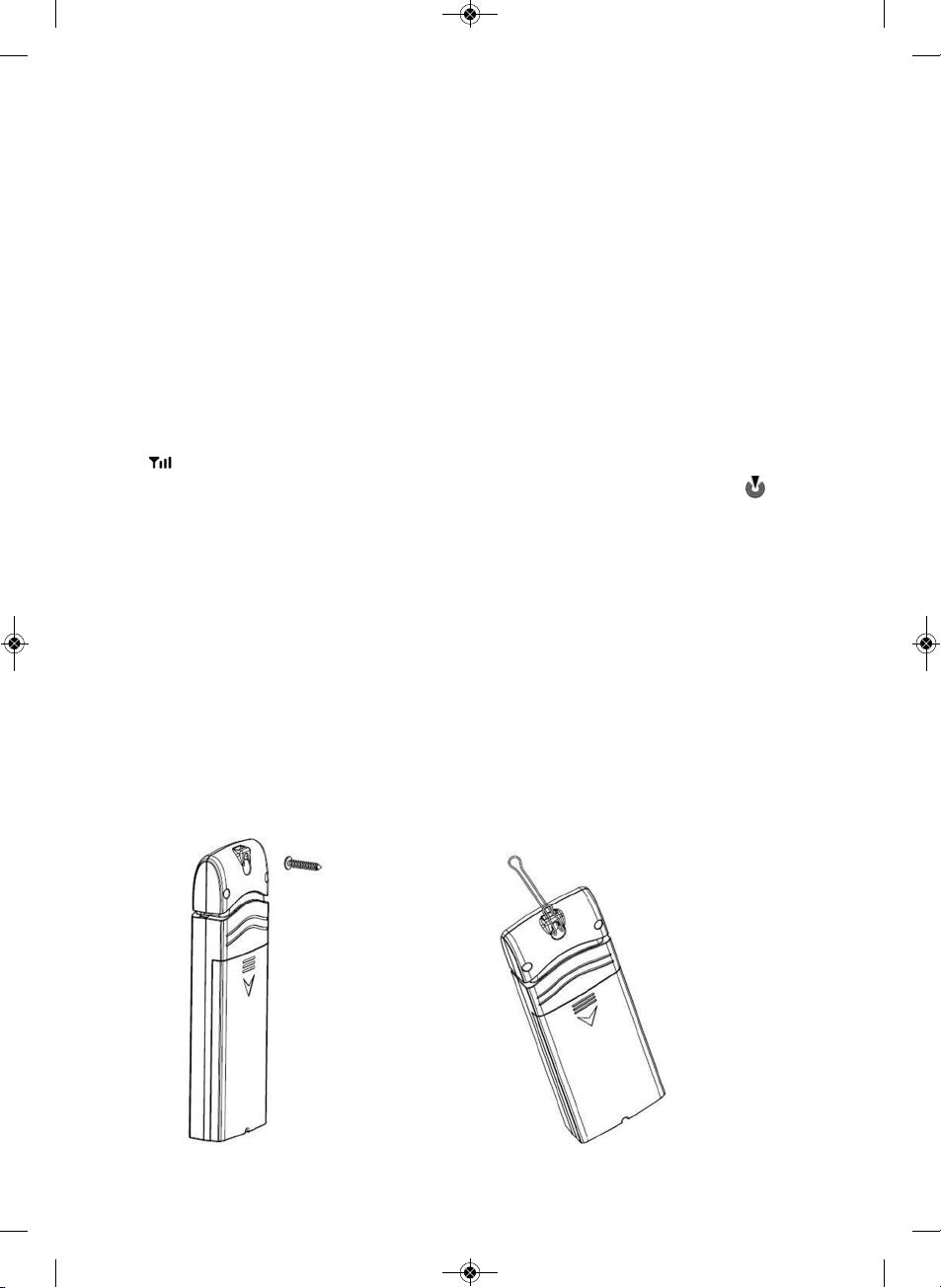
1. Use a screw or nail to affix the remote sensor to the wall, as shown in Figure 7
2. Hang the remote sensor up on string, as shown in Figure 8.
Figure 7 Figure 8
RST01938Manual 20.10.2017 13:20 Страница 6

RST01937 meteostanciya page 7
5. Program modes
5.1 Normal display Mode
1. Graph for Temperature/Dew point/heat index/humidity of ndoor/outdoor sensors.
2. Date and time.
3. Outdoor Temperature/Dew point/heat index/humidity for channel 1 and other channels de-
fined to be displayed in CH1 area in turn.
4. Outdoor Temperature/Dew point/heat index/humidity for channel 2 and other channels de-
fined to be displayed in CH2 area in turn.
5. Outdoor Temperature/Dew point/heat index/humidity for channel 3 and other channels de-
fined to be displayed in CH3 area in turn.
6. Outdoor Temperature/Dew point/heat index/humidity for channel 4 and other channels de-
fined to be displayed in CH4 area in turn.
7. Outdoor Temperature/Dew point/heat index/humidity for channel 5 and other channels de-
fined to be displayed in CH5 area in turn.
8. Alarm icon
9. RCC reception icon
Figure 10
RST01938Manual 20.10.2017 13:20 Страница 7

page 8 RST01937 meteostanciya
After the console receives data from each remote sensor, user can press these 4 buttons for op-
eration.
Icon Description
Graph key Switch to display graph of Temperature/
Dew point/heat index/humidity for all sensors
Brightness control key Press this key to increase the brightness
Brightness control key Press this key to decrease the brightness
Menu Key Press this key to enter menu and scroll to different modes
5.2 Setup Mode
Under Normal mode, press MENU key once to enter Setup Mode.
Figure 11
con Description
Scroll right key. Press this key to scroll down/right.
Selection key. Press this key to select and enter the option.
Scroll left key. Press this key to scroll up/left.
Mode key. Press this key to enter to next mode
RST01938Manual 20.10.2017 13:20 Страница 8

RST01937 meteostanciya page 9
Scroll to selected channel area, and press key to enter the setting interface as below:
To modify the display parameter, press the up/down and left/right keys to move the
blue cursor to a sensor channel number (1-8) and parameter (temperature, dew point, heat
index). Press key to display this channel and parameter in the selected area on the main
screen. For example, if you wish to display Channel 1 Dew Point in the CH Area 1, highlight the
Channel 1 Dew point field.
f you wish to toggle both channel 1 temperature and channel 1 dew point, highlight both the
Channel 1 Temperature and Channel 1 Dew Point (reference Figure13),, and the screen will tog-
gle between the channel 1 temperature and dew point on the main screen once every 3 sec-
onds.
f you wish to toggle both channel 2 temperature and channel 5 Dew point in the CH Area 2,
highlight both the Channel 2 Temperature and Channel 5 Dew point, and the screen will toggle
between the channel 5 temperature and dew point in the CH Area 2 once every 3 second.
Note: CH Area 1 can’t shift display other channel parameter and just display channel 1 sensor
parameter.
Graph Time
To change the Graph Time on the main display, scroll to the Graph Time, and select the
key to change between 12, 24, 48 and 72 hours.
con Description
Scroll right key. Press this key to scroll down/right.
Selection key. Press this key to select and enter the option.
Scroll left key. Press this key to scroll up/left.
Return key. Press this key to back to Setup main menu.
Figure 13
RST01938Manual 20.10.2017 13:20 Страница 9

page 10 RST01937 meteostanciya
Time Format
To change the Time Format on the main display, scroll to the Time Format, and select the
key to change between AM h:mm:ss, hh:mm:ss AM (12 hour time format) and h:mm:ss (24
hour time format)
Date Format
To change the Date Format on the main display, scroll to the Date Format, and select the
key to change between MM-DD-YYYY, DD-MM-YYYY and YYYY-MM-DD.
Date and time
This is to set time, date, DST, and time zone.
The console receives the radio controlled time signal from one wireless sensors. The time and date
will set automatically, and adjust for Daylight Savings Time (DST). To work properly, you must enter
the time zone and DST. You can also manually enter the time.
To manually change the time and data settings, scroll to the field you wish to change, and
press the or key to adjust up or down.
Turn N the DST setting, unless you reside in the place which do not observe Daylight Savings
Time.
Adjust your time zone according to the table below:
Hours from GMT Time Zone Cities
-12 DLW: nternational Date Line West ---
-11 NT: Nome Nome, AK
-10 AHST: Alaska-Hawaii Honolulu, H
Standard CAT: Central Alaska HST:
Hawaii Standard
Figure 14
RST01938Manual 20.10.2017 13:20 Страница 10

RST01937 meteostanciya page 11
Hours from GMT Time Zone Cities
-9 YST: Yukon Standard Yukon Territory
-8 PST: Pacific Standard Los Angeles, CA, USA
-7 MST: Mountain Standard Denver, CO, USA
-6 CST: Central Standard Chicago, L, USA
-5 EST: Eastern Standard New York, NY, USA
-4 AST: Atlantic Standard Caracas
-3 --- Sгo Paulo, Brazil
-2 AT: Azores Azores, Cape Verde slands
-1 WAT: West Africa ---
0 GMT: Greenwich Mean WET: London, England
Western European
1 CET: Central European Paris, France
2 EET: Eastern European Athens, Greece
3 BT: Baghdad Moscow, Russia
4 --- Abu Dhabi, UAE
5 --- Tashkent
6 --- Astana
7 --- Bangkok
8 CCT: China Coast Bejing
9 JST: Japan Standard Tokyo
10 GST: Guam Standard Sydney
11 --- Magadan
12 DLE: nternational Date Line East Wellington, New Zealand
NZST: New Zealand Standard
Temperature Units
To change the temperature units of measure, scroll to the Temperature Units field, and
press the key to toggle between °F and °C.
5.3 Calibration Mode
Under Normal mode, press MENU key twice to enter Calibration Mode. Users can calibrate the
temperature and humidity of wireless sensors here.
RST01938Manual 20.10.2017 13:20 Страница 11

page 12 RST01937 meteostanciya
Scroll to the temperature or humidity field you wish to calibrate, press the key to per-
form the calibration, and press the or key to match your calibration source.
con Description
Scroll down/right key
Press this key to scroll down/right.
Selection/value increase key
Press this key to select parameter and enter the calibration interface. ncrease the
value during calibration.
Selection/value increase key
Press this key to sele t parameter and enter the alibration interfa e.
In rease the value during alibration.
Scroll left key
Press this key to scroll up/left.
Mode key
Press this key to enter to next mode
Return Key
Back to main menu of calibration mode.
Resume Key
Cancel the calibration and resume.
RST01938Manual 20.10.2017 13:20 Страница 12

RST01937 meteostanciya page 13
5.3.1 Notes about Calibration
Note: The calibrated value can only be adjusted on the console. The remote sensor(s) always
displays the un-calibrated or measured value.
Note: The measured humidity range is between 10 and 99%. Humidity cannot be accurately
measured outside of this range. Thus, the humidity cannot be calibrated below 10% or above
99%.
The purpose of calibration is to fine tune or correct for any sensor error associated with the devices
margin of error. The measurement can be adjusted from the console to calibrate to a known
source.
Calibration is only useful if you have a known calibrated source you can compare it against, and
is optional. This section discusses practices, procedures and sources for sensor calibration to re-
duce manufacturing and degradation errors. Do not compare your readings obtained from
sources such as the internet, radio, television or newspapers. They are in a different location and
typically update once per hour.
The purpose of your weather station is to measure conditions of your surroundings, which vary sig-
nificantly from location to location.
5.3.2 Humidity Calibration Methods
Official stations recalibrate or replace humidity sensors on a yearly basis. Due to manufacturing
tolerances, the humidity is accurate to ± 5%. To improve this accuracy, the indoor and outdoor
humidity can be calibrated using an accurate source, such as a sling psychrometer or one step
humidpak calibration kits.
5.3.3 Temperature Calibration Methods
Temperature errors can occur when a sensor is placed too close to a heat source (such as a build-
ing structure, the ground or trees).
To calibrate temperature, we recommend a mercury or red spirit (fluid) thermometer. Bi-metal
(dial) and other digital thermometers are not a good source and have their own margin of error.
Using a local weather station in your area is also a poor source due to changes in location, timing
RST01938Manual 20.10.2017 13:20 Страница 13

page 14 RST01937 meteostanciya
(airport weather stations are only updated once per hour) and possible calibration errors (many
official weather stations are not properly installed and calibrated).
Place the sensor in a shaded, controlled environment next to the fluid thermometer, and allow
the sensor to stabilize for 48 hours. Compare this temperature to the fluid thermometer and adjust
the console to match the fluid thermometer.
5.4 Max/Min & Alarm Mode
Under Normal mode, press MENU key three times to enter Max/Min & Alarm Mode. Users can
check max/min records of temperature, humidity, dew point, heat index of each sensor. And ice
warning, high/low alarms of humidity and temperature can be configured here.
con Description
Scroll down/right key
Press this key to scroll down/right.
Selection/value increase key
Press this key to select parameter and enter the calibration interface. ncrease the
value during calibration.
Selection/value increase key
Press this key to sele t parameter and enter the alibration interfa e.
In rease the value during alibration.
Scroll left key
Press this key to scroll up/left.
Mode key
Press this key to enter to next mode
Return Key
Back to main menu.
Resume Key
Cancel.
RST01938Manual 20.10.2017 13:20 Страница 14

RST01937 meteostanciya page 15
5.4.1 Max/Min
Scroll to the temperature, humidity, dew point or heat index min/max field you wish to view,
and press the key. Note that dashes (--.-) will be displayed for sensors that are not pro-
grammed for your system.
Temperature Max/Min interface
To clear all of the min and max values, refer to Section5.5.2 for details.
Humidity Max/Min interface
RST01938Manual 20.10.2017 13:20 Страница 15

page 16 RST01937 meteostanciya
Dew point Max/Min interface
Heat index Max/Min interface
5.4.2 Alarm
You can set a high and low temperature and humidity alarm on Channels 1-8. f the measured
value is greater than the high alarm, an audible alert will sound and the alarm icon will flash
on the alarm panel, and the red color alarm icon will appear on the main panel.
f the measured value is less than the high alarm, an audible alert will sound and the alarm icon
will flash on the alarm panel, and the grey color alarm icon will appear on the main panel.
When an alarm has been triggered, the alarm will sound for 120 second and the corresponding
alarm icon will flash until the alarm condition is no longer met.
RST01938Manual 20.10.2017 13:20 Страница 16

Press any key to silence the alarm. The alarm icon is color coded, and will flash as shown in table
if one or more alarms are triggered:
Alarm Type color
High Alarm Red – grey - red
Low alarm Blue – grey - blue
High alarm & Low alarm both activated Red – grey – blue – grey – red
Beep alarm stop grey
Scroll to the Humidity or Temperature Alarm On/Off switch, and press the key to tog-
gle the Humidity or Temperature Alarm On or Off.
Scroll t to the Humidity Alarm or Temperature Alarm field, and press the key to display
the alarm programming panel, as shown in Figure 24.
Note: The alarm must be turned On to program the alarm settings.
Referring to Figure 24, scroll to the channel and alarm limit, and press the or
key to adjust the alarm limit up or down.
Scroll to the alarm field and press the key to turn the alarm bell on our off to activate
the alarm.
RST01937 meteostanciya page 17
RST01938Manual 20.10.2017 13:20 Страница 17

page 18 RST01937 meteostanciya
Figure24
5.5 Factory
Under Normal mode, press MENU key four times to enter factory mode.
Figure25
5.5.1 Factory reset:
To restore to factory default, scroll to the Factory Reset field and press to clear all set-
tings and restore to factory default.
5.5.2 Clear Max/Min:
To clear all of the max and min values, scroll to the Clear Max/Min field and press to
view the clear Max/Min panel. Scroll the sensor you wish to clear, and press to clear the
stored max and min values of this sensor..
con Description
Scroll down/right key
Press this key to scroll down/right.
Selection/value increase key
Press this key to select parameter to set alarm thresholds and turn on the alarm icon.
Red alarm icon is high alarm. Blue one is low alarm.
Selection/value increase key
De rease the value during alarm setup.
Scroll left key
Press this key to scroll up/left.
Mode key
Press this key to back to main menu or enter to next mode
Return Key
Back to main menu of alarm menu.
RST01938Manual 20.10.2017 13:20 Страница 18

RST01937 meteostanciya page 19
Figure26
5.5.3 Re-register sensors:
f sensor communication is lost with a specific sensor, you can re-acquire. Scroll to the re-
register sensors field, and press to view the re-register panel. Scroll the sensor you wish to
register, and press to re-acquire this sensor. Press the button to highlight Yes and press
to confirm. f the indoor sensor display -- --, please scroll to it and enter to Re-register the
indoor sensor. .
5.5.4 About:
Scroll to the About field, and press to view the hardware and firmware version.
Figure27
5.5.5 Language:
Scroll to the Language field, and press to change the language.
RST01938Manual 20.10.2017 13:20 Страница 19

page 20 RST01937 meteostanciya
5.5.6 Backlight:
Scroll to the BackLight field, and press to adjust the backlight features. To turn on and
off the back lit display at certain times during the day, scroll to the Backlight control field,
and select the key to check the Backlight Conrol switch. Scroll to adjust the backlight
on and off time. Press the or keys to adjust the hours and minutes up or down. .
Figure28
6. ther Features
6.1 SD Card Export and Firmware Updates
With the use of an optional Micro SD Card, you can export data to a computer, save historical
graphs (in the event of a power failure) and update firmware when new versions are released.
6.1.1 SD Data Export
The console includes a micro SD / TF card slot on
the right side, as shown in Figure 2. Backup data to
micro SD / TF card (see the Accessories section of
this manual for more information on micro SD / TF
cards). The SD card will record data into the H S-
TORY directory.
The file is comma separated value (csv) and can
be imported into Microsoft Excel, or other text
based applications.
The file format is as follows: YYYYCH#A where YYYY
is the year, # is the channel number and A is the re-
vision letter.
Example: 2018CH2A is the data for 20168, Channel 2, and A is the revision letter each time you
change a units of measure or calibration setting. Below is an example of the file output: Time,
Temperature(F), Humidity(%), Dewpoint(F), Heat ndex(F) 2018/02/18 08:05,48.7,32,20.3,48.7
2018/02/18 08:10,49.1,33,21.2,49.1 2018/02/18 08:15,49.1,31,19.8,49.1
Figure 29
RST01938Manual 20.10.2017 13:20 Страница 20
This manual suits for next models
1
Table of contents
Languages:
Other RST Weather Station manuals

RST
RST IQ785 User manual

RST
RST RST02875 User manual

RST
RST RST02557 User manual

RST
RST IQ889 User manual

RST
RST RST02711 Series User manual

RST
RST meteolight Q776 User manual

RST
RST meteolight Q776 User manual

RST
RST 02876 User manual

RST
RST METEO PROJECTION 703 User manual

RST
RST meteolight Q774 User manual