Rupes LH31N Manual

ISTRUZIONI ORIGINALI PER L'USO E LA MANUTENZIONE
ORIGINAL OPERATING AND MAINTENANCE INSTRUCTIONS
NOTICE ORIGINAL D'EMPLOI ET D'ENTRETIEN
ORIGINAL-BEDIENUNGS-UND WARTUNGSANLEITUNG
INSTRUCCIONES ORIGINAL DE USO Y MANUTENCION
AANWIJZINGEN VOOR HET GEBRUIK EN HET
ONDERHOUD ORIGINEEL
ИНСТРУКЦИЯ ПО ЭКСПЛУАТАЦИИ И
ОБСЛУЖИВАНИЮ
1
ОРИГИНАЛЬНЫЙ
Levigatrici angolari
Angular sanders
Ponceuses angulaires
Winkelschleifer
Lijadoras angulares
Haakse slijpmachines
Угловые полировальные машины
LH31N - LH32EN
LH232N
Via Marconi, 3A - 20080 VERMEZZO (Mi) - Italy
Tel. 02/946941 - Fax 02/94941040
e-mail: info_rupes@rupes.it -web: www.rupes.com


8
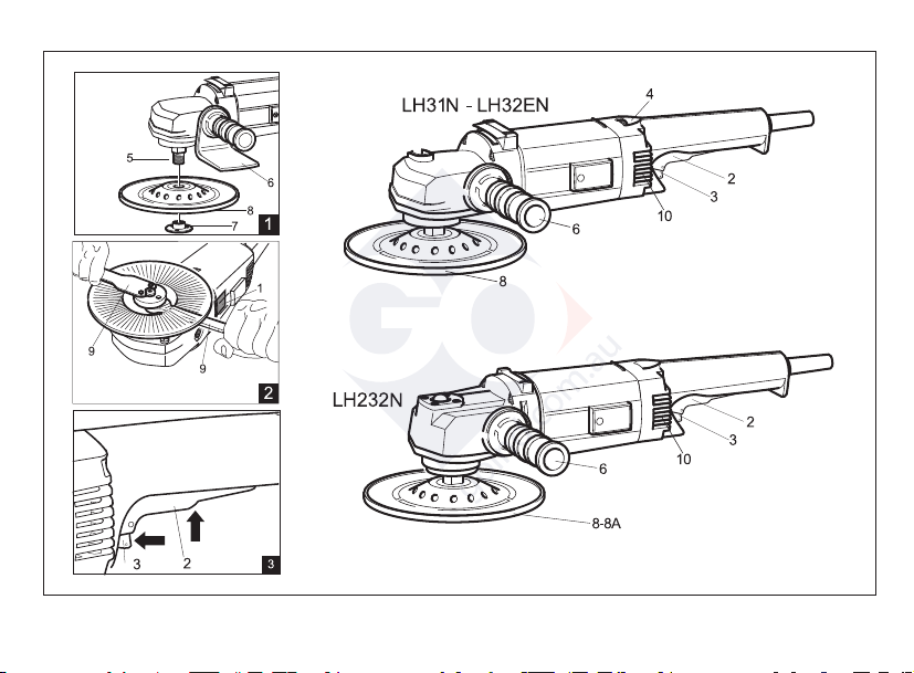
TYPE LH232N LH31N LH32EN
INSULATION CLASS II II II
ABSORBED POWER 1200 W 1200 W 1200 W
ELECTRONIC OVERLOAD PROTECTION NO NO YES
ELECTRONIC SPEED CONTROL NO NO YES
ROTATION RPM 1600÷3400 3400 1400÷3400
MECHANICAL SPEED CONTROL YES* NO NO
ABRASIVE DISC DIAMETER mm 178 178 178
BUFFER DIAMETER MAX mm 200 — —
SPINDLE THREAD M14 M14 M14
WEIGHT Kg 3,7 3,3 3,3
TECHNICAL DATA ENGLISH
GENERAL WARNINGS
The safety and accident prevention instructions are reported in
the “SAFETY INSTRUCTION” booklet which forms an integral part
of these documents. This OPERATING INSTRUCTIONS MANUAL
indicates the additional information required specifically for use
of the tool.
CORRECT USAGE
This tool is designed to be used as a polisher. Read all the
warnings, instructions, indications provided on drawings and
specifications supplied with this tool. Failure to comply with all the
instructions provided below may cause electrical shocks, fires and/or
serious injuries.
This tool is not intended to be used for smoothing, metal
brushing and cutting operations. The use of this tool for unintended
applications may cause hazards and injuries to people.
The tool must be used with accessories that have been
specifically designed or recommended by the manufacturer. The
fixing of the accessory to the tool does not guarantee a safe
operation.
The rated speed of the accessories must be at least equivalent to
the maximum speed specified on the tool. Using the accessories
at speeds above the rated one, may cause them to break or be
projected into the air.
The external diameter and thickness of the accessories must
match the specifications of the tool. Accessories with incorrect
dimensions cannot be adequately protected or controlled.
The configuration of accessories must match the tool. The use of
accessories that cannot be perfectly fitted on the tool may result in
imbalance, excessive vibrations and in the impossibility of controlling
the tool.
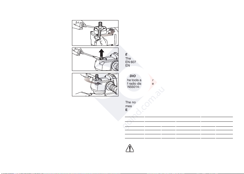
Do not use damaged accessories. Before use, inspect all the
accessories. Inspect the supporting pads and verify there are no
cracks, tears or excessive wear. If the tool or accessory has
fallen, verify that it is not damaged or install a new accessory.
After inspecting or installing an accessory, test the operation of
the tool at maximum speed and without load for one minute,
keeping at a safety distance. If the accessories are damaged, they
will break during this test.
8
The values shown are based on a nominal voltage of 230V/50Hz. In the case of voltages and frequencies of different power values may
vary. Refer to the label technical specifications to the nominal values of the tool.
(*) The tool must be connected to a suitable dust extraction system (not supplied).
according to EPTA-Procedure 01/2003

9
SAFETY WARNINGS APPLICABLE TO POLISHING OPERATIONS
Verify that no loosened part of the polishing tool shroud or the
locking ties can rotate freely. Safely position or cut all the loosened
fixing wires. Loosened or revolving fixing wires may twist around the
operator’s fingers or get caught by the work piece being machined.
PARTS OF THE TOOL
1 - Identification plate
2 - Switch lever
3 - Switch block
4 - Electronic rpm regulation
5 - Spindle
6 - Auxiliary handle
7 - Buffer pad and abrasive disc tapered ring nut
8 - Buffer pad (on request) (LH232N)
8A - Vulcofix pad (on request) (LH232N)
9 - Wrenches (17 mm spanner and pin spanner)
10 - Motor ventilation slots
STARTING UP
Before starting-up the tool ensure that:
- the packaging is complete and does not show signs of having been
damaged during storage or transport;
- the tool is complete; check that the number and type of components
comply with that reported in this instruction booklet;
- the power supply and socket outlet can support the load reported in the
table and that indicated on the tool identification plate reproduced and
explained on page 11.
ASSEMBLING THE TOOL
Assemble the handle (6); these can be positioned either on the left or
right of the tool body.
MOUNTING THE VULCOFIX PAD AND BUFFER PAD
If working with machines:
1. Insert the vulcofix pad (8A) on the spindle (5) (fig. 1).
2. Insert the abrasive disc;
3. Screw on the tapered ring nut (7) and tighten it using the pin spanner,
preventing the spindle from moving using the 17 mm. spanner (fig. 2).
BEFORE STARTING THE TOOL
Ensure that:
- the power supply conforms with the characteristics of the tool;
- the power supply cable and plug are in perfect condition;
- the ON/OFF switch works properly though with the power supply
disconnected;
- all the parts of the tool have been assembled in the proper manner and
that there are no signs of damage;
- the ventilation slots are not obstructed.
STARTING AND STOPPING
- Starting:move the switch lever (2) up; to lock it in "engaged" position,
move the switch block (3) forward towards the machine body.
- Stopping: : release the switch lever (2); if the switch is in "engaged"
position, move the switch lever (2) up in order to release the switch
block (3).
Warning! The tool continues to rotate after it is turned off.
Wait until it has come to a full stop before laying it down.
TEST RUN
Start the tool and check that there are no unusual vibration, no
dismatching of the buffer pad or of the abrasive disc.
Otherwise, switch-off the tool immediately and eliminate the cause.
ELECTRONIC SELECTING RPM (LH32EN)
The rpm can be adjusted by rotating the wheel (3). The choice of speed
depends on the characteristics of the abrasive disc and the material to be
worked.

10
USING THE LH232N MODEL AS A POLISHER
(1600 rpm)
(A)
- Insert a screwdriver in the special slot
to lock the spindle (5);
- use the 17 mm spanner to unscrew
the spindle.
(B)
Remove the plug (as in figure B) and
screw the threaded spindle previous
removed from the lower housing in the
seating.
(C)
- Insert a screwdriver in the specific
housing to block the shaft;
- tighten the shaft with the 17 mm wrench.
You can now use the tool as a polisher
after assembling the disk following the
instructions in the booklet.
DISMOUNTING AND REPLACING ABRASIVE DISCS
(LH31N - LH32EN - LH232N)
- Hold the spindle still with the 17 mm. spanner;
- unscrew the tapered ring nut, loosening it with the pin spanner;
- replace the used abrasive disc;
- re-tighten the tapered lock nut and lock it in position using the pin spanner.
The use of any other tool is strictly prohibited.
USABLE WORKING TOOLS
LH31N - LH32EN - LH232N
Ø 178 mm abrasive discs.
LH232N
Buffer pads and buffers up to 200 mm Ø.
MAINTENANCE
All maintenance operations are carried out with the power supply
disconnected.
At the end of each work session, or when required, remove any dust from
the body of the tool using a jet of compressed air, paying particular
attention to the motor ventilation slots.
No other maintenance operations must be undertaken by the user.
Maintenance and cleaning of the inner parts, like brushes, ball
bearings, gears etc. or others, must be carried out only by an
authorised customer-service workshop.
ELECTRIC SAFETY - LOW TENSION
The tests have been carried out in accordance with the standard:
EN 60745-1 safety of hand-held electric motor operated tools
EN 60745-2-3 particular requirements for polishers.
RADIO SUPPRESSION
The tools are suppressed in accordance for the prevention and elimination
of radio disturbances measured in accordance with standard: EN55014-1+
EN55014-2; EN61000-3-2+EN61000-3-3.
NOISE / MEAN ACCELERATION VALUE
The noise level produced and themean quadratic acceleration value are
measured according to regulation
EN 60745-1
Sound pressure level / Sound power level 3 axis vibration level
LPA LWA Uncertainty ahUncertainty
dB(A) m/s2
LH31N 81 92 3 2,3 0,5
LH32EN 81 92 3 2,3 0,5
LH232N 85 96 3 2,5 1
Danger! The indicate measurements refer to new power tools. Daily usa
causes the noise and vibration values to change.

11
We declare on our responsability that the hand-held motor operated tool, which is
mentioned in the present operating manual, is in comformity with the Essential Re-
quirements of Safety of the following Directives:
The tests have been carried out in accordance with following Standards:
Technical file at:
RUPES S.p.A.
Via Marconi, 3A
20080 VERMEZZO (Mi) - Italy
Vermezzo (MI), 24/01/2018
CONFORMITY DECLARATION
IL PRESIDENTE
G. Valentini
S.p.A
2006/42/CE, 2014/35/CE, 2014/30/CE, 2011/65/CE.
EN 60745-1:2009 + A11:2010
EN 60745-2-3:2011 + A2:2013 + A11:2014 + A12:2014 + A13:2015
EN 55014-1:2006 + A1:2009 + A2:2011
EN 55014-2:1997 + A1:2001 + A2:2008
EN 61000-3-2:2014
EN 61000-3-3:2013
EN 62233:2008
EN 50581:2012
DISPOSAL
For EC countries only: According to the European Directive on
Waste from electrical and electronic equipment and its
implementation in conformity with national standards, exhausted
electrical equipment must be collected separately, in order to be
recycled in an environmentally friendly way. The product, when it
reaches the end of its life, must not be dispersed in the environment or
thrown away as household waste. It must be disposed at authorized
recycling centres (contact your local authorities to know where to
dispose of the product according to the law). The correct disposal of the
product contributes to the health and preservation of the environment.
Illegal disposal of the product will entail penalties against the offenders.
Disposing of the product correctly contributes to protecting human
health and safeguarding the environment. Any illegitimate disposal of
the product will be punishable by law.

COD. ART. 9.2414 - REV 1 GENNAIO 2018
RUPES S.p.A.
Via Marconi, 3A
20080 VERMEZZO (Mi) - Italy
Tel. 02/946941
Fax 02/94941040
Uff. Vendite e assistenza clienti
Tel. 02/94694312
e-mail: [email protected]
web: http://www.rupes.com
Other manuals for LH31N
1
This manual suits for next models
2
Table of contents
Other Rupes Sander manuals