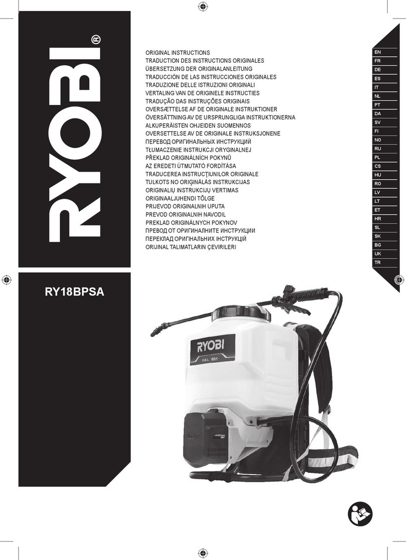
Ryobi GS-400 Operation manual

6986307 (STD)
06-11

- 1 -
1
11
5
1
4
6
12
10
3
2
9
7
13
8

- 2 -
Fig. 2
15
14
1
16
12
2a 3
Fig. 3
12
3
23
4
2
23

- 3 -
Fig. 5
1, 2 3
Fig. 4
12
3
3
5
6
10 10
12
Fig. 6
STOP
START

- 4 -
THANK YOU FOR BUYING A RYOBI PRODUCT.
To ensure your safety and satisfaction, carefully read
through this OWNER’S MANUAL before using the prod-
uct.
WARNING! THIS PRODUCT IS DESIGNED TO SPRAY
CHEMICALS THAT MAY BE HARMFUL AND COULD
CAUSE SERIOUS PERSONAL INJURY IF INHALED OR
BROUGHT INTO CONTACT WITH THE USER.
WARNING! READ ALL INSTRUCTIONS BEFORE USE.
FAILURE TO FOLLOW ALL INSTRUCTIONS LISTED BE-
LOW AND/OR MISUSE OF THIS PRODUCT MAY SERIOUS
INJURY.
SAFETY INSTRUCTIONS
1. Wear long sleeve shirts, long pants, gloves, safety
glasses, respirator, and protection shoes.
2. Examine the sprayer overall before every time usage and
make sure the sprayer is no problem in usage.
3. Do not spray hot water, combustible, corrosive or highly
acidic liquids.
4. Do not face directly the upright of the pressure barrel
when pump, pressurize or dismantle the pump.
5. Do not expose the sprayer with pesticide under the sun.
6. Once the pressure barrel or rubber duct is damaged or
breach, do not pressurize to use.
7. Do not pressurize by means of mechanical devices, such
as air compressor.
8. Neverlltankabovethetoploneonthetank.
9. Before any maintenance, adjustment, cleaning or storing
the pump, make sure that pressure in the pump has been
released completely.
10. Before storing, wash thoroughly inside and outside of the
pump and barrel, then inject clean water into the pump
and spray for one minute so as to clean inside.
11. Do not store liquids in the tank.
12. Sprayer should be put in a safety place out of Children’s
reach.
13. Do not alter the sprayer or any components.
DESCRIPTION
1. Hose nut
2. Flow control hose nut
3. Flow control
4. Hose
5. Wand
6. Wand nut
7. Pump assembly
8. Tank
9. Pump handle
10. Flow control lever
11. Cone nozzle
12. Flow control cap
13. Pressure relief valve
14. Siphon tube
15. Hose insert
16. Threaded tank nipple
SPECIFICATIONS
GS-400 GS-600
Tank capacity 4littre 6littre
Working pressure 0.15 - 0.3Mpa 0.15 - 0.3Mpa
Hose length 1.2m 1.2m
Net weight 1.20kg 1.30kg
ASSEMBLY
HOSE TO TANK ASSEMBLY (Fig. 2)
1. Insert the siphon tube (14) into the hose insert (15)
otherwise sprayer will spray only air.
2. Lubricate the o-ring on the hose insert and then push into
the threaded tank nipple (16) until fully seated.
3. Screw hose nut (1) onto threaded tank nipple. Firmly
tighten it by hand.
FLOW CONTROL TO HOSE (Fig. 3)
1. Remove the flow control hose nut (2) from the flow
control (3) and slide over the hose (4).
2. Push the hose over the pointed end of the ow control
until it touches the threads.
3. Screw the flow control hose nut onto the flow control.
Firmly hand-tighten.
WAND TO FLOW CONTROL (Fig. 4)
1. Pushthewand(5)intotheowcontroluntilitstops.
2. Slidetheo-ringdownuntilittouchestheowcontrol.
3. Screwthewandnut(6)ontotheowcontrol.Firmlyhand
tighten.
IMPORTANT: TO ENSURE CORRECT ASSEMBLY, TEST
SPRAYER WITH WATER BEFORE USING.
FILLING THE SPRAYER
1. Remove the pump assembly (7) from the tank (8) by
turning counter-clockwise.
2. Prepare the spray solution following the instructions
listed on the chemical manufacturers’ label. Mix only the
amount of solution to be sprayed.
3. Screw the pump assembly back into the tank by turning
clockwise. Firmly hand tighten.
WARNING!
• Donotsprayammable,caustic(i.e.acids,chlorinesand
bleach), corrosive, heated or self-heating solutions with
this sprayer.
• Neverlltankabovethetoplineonthetank.
PRESSURIZING THE SPRAYER
1. Unlock the pump handle (9) by pressing down and
turning it until the hooks under the handle are positioned
on the slit. Be careful not to loosen the pump.
2. To create pressure, stroke up and down until you feel
difculttostrokedown.
3. Lock the pump handle back into the pump assembly by
pressing down and turning it.
WARNING! To prevent ejected pump assembly and/or
solution from striking and injuring you, never stand with your
face or body directly over the top of the tanks when pumping
or loosening the pump.
SPRAYING (Fig. 5)
1. Tostartspraying,squeezetheowcontrollever.(10)
2. Tostopspraying,releasetheowcontrollever.
3. Tospraycontinuously,squeezetheowcontrolleverand
slide forward to lock on.
4. If your sprayer has an adjustable cone nozzle (11), screw
thenozzleclockwiseforanemistandcounter-clockwise
for a coarse stream.
WARNING! (Fig. 6)
• DONOTremoveowcontrolcap(12)whilespraying.
• ALWAYSwearlongsleeveshirts,longpants,goggles,
gloves and durable shoes.


- 5 -
RELEASING PRESSURE
1. To release pressure from the tank, turn the tank upside
down,andthensqueezetheowcontrolleveruntilallthe
air pressure is gone, or pull the pressure relief valve (13)
until all air pressure is gone.
2. If your sprayer is clogged and the pressure will not
releaseusingtheowcontrol,dothefollowing:
a. Place a rag over the top of the sprayer and pump.
b. While firmly pushing down on the pump handle, slowly
turn counter-clockwise.
WARNING!
• ALWAYSRELEASEpressureinsprayerbeforeservicing.
• NEVERleavepressurizedsprayerunattended.
CLEANING
Toprolongitslife,cleanthesprayeraftereachuse.Afterusing
water-based products, rinse thoroughly with soapy water
then clean water, being sure to flush out the hose and flow
control.Aftersprayingsolventoroil-basedproducts,followthe
chemical manufacturers’ recommended cleaning procedure,
followingupwithathoroughrinsingandushingofthesprayer,
hoseandowcontrolwithsoapywaterthencleanwater.
WARNING! Do not store chemicals in the tank. If the chemical
is stored in the tank, it can clog the system as it dries and
destroy the seals and other components.
STORAGE
1. Remove the complete hose assembly (hose w/siphon
tube,wand,owcontrol)fromthetank.
2. For proper drainage and drying, lock ow control lever
on.
3. Loosen pump assembly, but leave in the tank.
4. Store all components in a clean, dry area.
WARNING! Store the sprayer in a safety place out of
Children’s reach.
PUMP MAINTENANCE & DISASSEMBLY
Tokeepthepumpworkingsmoothlyandefciently,theplunger
o-ring needs to be lubricated often by applying grease or
petroleum jelly around the outside of the plunger o-ring.
1. Remove pump assembly from the tank.
2. Unlock the pump handle and pull it out as far as it will go.
3. Withaat bladescrewdriver, pushdownonthetabson
each side of the pump. Pull up and the handle and the
plunger assembly should come out of the pump cylinder.
• Toreassemble,inserttheplungerassemblyintothe
cylinder and snap the cap back into place.

- 6 -
PROBLEM CAUSE SOLUTION
Pump works hard or does not
pressurize the tank.
Plunger o-ring either not lubricated or
damaged.
Applypetroleumjellyorgrease
around outside of plunger o-ring.
Check for cracks or other damage
and replace if necessary.
Spray solution or air leaks into pump
cylinder. Check valve on bottom of cylinder
is prevented from sealing by dirt,
residue or damage.
Remove the pump assembly and
examine the check valve. Clean if
dirty; replace if necessary.
Hose leaks air at tank connection. Tank nut is loose. Tighten hose tank nut.
Hose insert o-ring is damaged. Replace hose insert o-ring.
Flow control leaks. Improper assembly. Refer to “Flow Control to Hose”
and “Wand to Flow Control”
assembly instructions.
Bad spray pattern or low spray
volume.
Nozzle is clogged. Remove nozzle and clean; remove
wand and clean.
Low pressure in sprayer. Re-pressurize the tank.
Nozzleleakswhenowcontrolis
closed.
Flow control remaining open (lever is
locked on).
Completelydisassembleow
control. Inspect all components,
clean and lubricate all seals or
replaceowcontrol.
Leak at tank opening. Pump assembly not sealed tightly
into tank.
Thoroughly clean pump cylinder
gasket or o-ring and surrounding
area and apply grease or
petroleum jelly to pump gasket or
o-ring.
Damaged pump cylinder gasket or
o-ring.
Replace gasket or o-ring.
Fluid leaks from pressure relief
valve.
Tankisoverlled. Release pressure by following
“Releasing Pressure” instructions.
DO NOT USE the pressure relief
valve for releasing pressure.
Removeexcessuid.
TROUBLESHOOTING

- 7 -

- 8 -
Ref. No Description
1 pump handle
2-8 pump assy
2 pump link
3 press the guide sleeve
4 cup block
5 bowl
6 air tube
7 felt washer
8 vent plug
9 pressure relieve valve lever
10 O-ring
11 pressure relieve valve body
12 O-ring
13 spring
14 block
15 key loop
16 back belt
17 Belt clamp
18 tank
19 add liquid outlet
20 O-ring
21-27 combination hose
21 small mash
22 induction manifold
23 seal embedded parts
24 O-ring
25 hose nut
26 hose
27 owcontrolhosenut
28-38 owcontrol
28 owcontrol
29 O-ring
30 owcontrolbody
31 pressure shaft
32 spring
33 O-ring
34 owcontrolcap
35 O-ring
36 O-ring
37 shaft
38 owcontrollever
39-45 spray lance and nozzle assy
39 Wand nut
40 case nut
41 case nut
42 O-ring
43 nozzle connecrer
44 O-ring
45 cone nozzle

- 9 -
NOTE

- 10 -
NOTE

RYOBI POWER EQUIPMENT
WARRANTY
Subject to the warranty conditionsbelow, this
RYOBI tool(hereinafter called “the Product”),
is warranted by Ryobi(hereincalled “the
Company”) to be free fromdefects in material
or workmanship for a period of 24 months
from the date of originalpurchase covering
both parts andlabour. Under the terms of
thiswarranty, the repair or replacement of
anypartshall be the opinion of the Company
or its authorised agent. Should service
becomenecessary during the warranty
period, the ownershouldcontact the
authorised Ryobiretailer fromwhom the
product waspurchased, or the nearest
Company branch office. In order to obtain
warranty service, the ownermust include the
SalesDocketand Warranty Certificate to
confirmdate of purchase.This Product is
sold by the dealer or agent as principal and
the dealerhasnoauthority from the Company
to give any additionalwarranty or guarantee
on the Company’s behalf except as herein
contained or herein referred to.
Warranty Conditions
Thiswarranty onlyappliesprovided that the
Product hasbeen used in accordance with
the manufacturer's recommendationsunder
normaluseandreasonablecare(in the
opinion of the Company) and such warranty
does not cover consumable components,
damage,malfunction or failureresulting from
misuse, neglect,abuse, or used for a purpose
for which it wasnotdesigned, or is notsuited
and no repairs, alterations or modifications
havebeen attempted by other than an
Authorised Service Agent. Thisguarantee
willnotapply if the tool is damaged by
accident or if repairsarise fromnormalwear
and tear.
Accessoriessuch as bits,blades, sanding
discs, cuttinglines, etc., are excluded from
thisguarantee.Normalconsumableparts,
such as carbonbrushes,bearings,chucks,
cord assembly’s, spark plugs, recoil pulleys
andbumpheadassembly’s arespecifically
excluded from this guarantee.
The Company accepts no additional liability
pursuant to thiswarranty for the costs of
traveling or transportation of the Product or
parts to and from the sevice dealer or agent
-which costsarenotincluded in the warranty.
Nothinghereinshallhave the effect of
excluding, restricting or modifying any
conditions,warranty, rightorliability imposed,
to the extent only that such exclusion,
restriction or modificationwouldrender any
term herein void.
THIS WARRANTY FORM
SHOULD BE RETAINED BY THE CUSTOMER AT ALL TIMES.
For your record and to assist in establishing date of purchase (necessary for in-warranty service), please
keep your purchase docket and this form, completed with the following particulars.
PURCHASED FROM:.........................................................................................................
ADDRESS OF DEALER:....................................................................................................
DATE:......................... MODEL NO................................ SERIAL NO.................................
Present this form with your Purchase Docket when Warranty Service is required.
STEVENS & CO (Pty) Ltd
604, 16th Street, Randjespark
Midrand, South Africa
Tel: +27 (11) 357-9600
Fax: +27 (11) 805-5541
email: [email protected]
P O Box 4059
HALFWAY HOUSE
1685, South Africa
This manual suits for next models
1
Table of contents
Other Ryobi Paint Sprayer manuals

Ryobi
Ryobi RY18BPSA User manual

Ryobi
Ryobi R18FG35E User manual

Ryobi
Ryobi SSP0501 User manual

Ryobi
Ryobi P2830A User manual

Ryobi
Ryobi DUET FPR300N Specification sheet

Ryobi
Ryobi EZCLEAN RY3112BA User manual

Ryobi
Ryobi OWS1880 User manual

Ryobi
Ryobi SSP050 User manual

Ryobi
Ryobi FPR2000 User manual

Ryobi
Ryobi RAP200G Specification sheet