manuals.online logo
Brands
  1. Home
  2. •
  3. Brands
  4. •
  5. Salus
  6. •
  7. Accessories
  8. •
  9. Salus SC428ZW Operation manual

Salus SC428ZW Operation manual

In The Box
Installation/
User Guide
SC428ZW
SmartPlug
(888) 387-2587
[email protected] •www.salusinc.com
Instructions may change without notice, always check
www.salusinc.com for the latest installation details.
Safety Instructions
Read these instructions carefully before installing and using the
Z-Wave SmartPlug and keep this guide in a safe place for future
reference.
• Verify compatibility with your home network before
installation.
• Follow all instructions provided by the manufacturer of your
home network regarding the addition of devices to your
connected home system. An authorized, qualied installer
may be required.
Salus accepts no responsibility for damage caused
by not following these instructions.
Product Introduction
The Salus Z-Wave SmartPlug switch is a connected AC switch
that is compatible with Z-Wave networks. This device provides
ON/OFF control and measures the power/energy consumption
of the attached AC appliance. Key features include:
• Quick and easy installation
• Support for Z-Wave connected home networks
• Support for loads up to 15Amps (resistive).
• SmartStart functionality using the QR code on the device.
SmartStart enabled products can be added into a Z-Wave
network by scanning the Z-Wave QR Code present on the
product with a controller providing SmartStart inclusion. No
further action is required and the SmartStart product will be
added automatically within 10 minutes of being switched on in
the network vicinity.
Compliance Note: This product can be operated in any
Z-Wave network with other Z-Wave certied devices from other
manufacturers. All AC powered nodes within the network will act as
repeaters regardless of vendor to increase reliability of the network.
act as signal repeaters regardless of manufacturer.
Note: Additional equipment may be required due to building
construction or materials, or other radio interference that may
reduce the radio range.
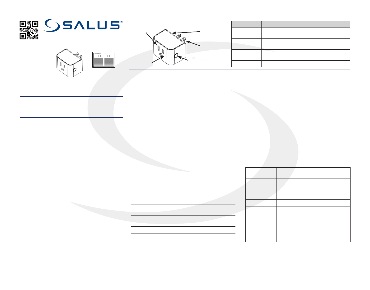
Item Description
Plug NEMA 5-15 (Type B) plug. Compatible with US
and Canadian 120VAC/15A electrical outlets
Socket NEMA 5-15 (Type B) outlet. Compatible with
US/Canadian 120VAC/15A electrical plugs
Multi Button Multi-function user input button: Pair, Rejoin,
Factory Defaults, and On/O
Hidden LED Red/Green LED status indicator
Controls and Indicators
Add (Include) a device to a network
• Refer to the instructions for your Z-Wave certied controller to
add a device to the Z-Wave network.
• Locate the Device Speci Key (DSK) label located on the back
(plug side) of the SmartPlug. Scan QR code to obtain DSK.
• Plug the SmartPlug switch into an AC outlet at the desired
location to account for any radio interference.
• Press the Multi Button once to initiate adding the device to the
network.
Remove (Exclude) a device from a network
• Refer to the instructions for your Z-Wave certied controller to
remove a device to the Z-Wave network.
• Press the Multi Button once to remove the switch from the
network.
Using the Switch
Note: After being plugged in, there is a slight delay before the
SmartPlug switch starts measuring energy and responding to the
button or remote commands.
Turn O/On
• Press the Multi Button to toggle the SmartPlug switch between
O and On.
Reset to Factory Defaults
• Press and hold the Multi Button for more than 10 seconds.
The amber LED will be illuminated for 2 seconds while it searches
for the network. Please use this procedure only when the network
primary controller is missing or otherwise inoperable.
Socket
Plug
Hidden LED
Multi
Button
531ESZA2AP1AC10
Troubleshooting
Will Not Pair
• Radio interference is present at the desired location.
1. Relocate the Z-Wave receiver,
2. Select a dierent location for the switch, or
3. Add a Z-Wave repeater to the system.
Loss of Connection After Pairing
• Make sure Z-Wave receiver is operating
• Radio environment may have changed:
1. Reset to factory defaults to search for a better path.
2. Apply radio interference solutions above.
No Appliance Power When Switch LED is On
• Make sure the attached appliance switch is on.
• Make sure the appliance can be controlled via the
AC supply.
Note: Appliances with “soft” on/o buttons cannot be turned on by
turning the AC supply ON.
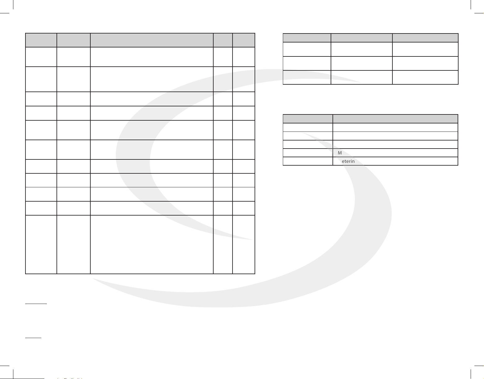
Specifications
Power up without Network Red LED ashes 5 times in
0.5 sec. on/0.5 sec. o
Power up with Network Red LED ashes 5 times in
0.2 sec. on / 0.1 sec. o
Relay is ON Green LED
Relay is OFF Red LED
Factory Reset Amber LED for 2 seconds
Overcurrent Protection Flashing Green
0.2 sec on / 0.2 sec. o
Operating
Conditions 32°F to 104°F (0°C to 40°C)
< 90% humidity (non-condensing)
Storage
Conditions -4°F to 185°F (-20°C to 85°C)
< 90% humidity (non-condensing)
Protocols
Supported Z-Wave
RF Frequency 908.42MHz, ISM band
Input 120VAC +/-10%, 60 Hz
Maximum
Switch Current 15 Amp resistive
Dimensions
(w x h x d)
Including Plug:
2.13” x 1.46” x 2.32” (54 x 37 x 59 mm)
Not including plug:
2.13” x 1.46” x 1.49” (54 x 37 x 38mm)
Z-Wave SmartPlug (SC428ZW)
Installation/User Guide
Basic Set Command
Basic Set (0x00) = Binary Switch Set (0x00)
Basic Set (0xFF) = Banary Switch Set (0xFF)
Basic Get = Binary Switch Get
Basic Report = Binary Switch Report
DSK Label
(located on
back)
Events
Association Group
Using association group, the Smart Plug is able to command or notify another device
of a Z-Wave® network.
Group Group Name
1Lifeline
2Follow State
3Follow Complementary State
4Metering - High Threshold-Set On/Off
5Metering - Low Threshold-Set On/Off
SMC-QG-SC428ZW-202101v1
Z-Wave User Configuration
Parameter Description Values Size
Byte) Default
1Status when
powered up
0 = Off
1 = On
2 = Status when last powered
1 2
3
Enable/
Disable for
Group 2 & 3
0 = Group 2 & 3 disabled
1 = Group 2 enabled
2 = Group 3 enabled
3 = Group 2 & 3 enabled
1 3
5Overvoltage
Alarm (V) 1-200 = Overvoltage Alarm threshold 2132
6Overcurrent
Alarm (mA) 1-15000 = Overcurrent Alarm threshold 215000
21
Power
Change
Report
1 - 100 = % Power Change to Send Report 110
22
Overload
Power Re-
port
1 – 1980 = 1 to 1980W 21980
23 Energy
Report 1 – 327 = 1 KWh to 327 KWh 2 1
24 Metering
Report 30 – 32767 = 30 – 32767 seconds to send report 23600
25 High Power
Threshold
0 = High Power Threshold disabled
1 – 32767 = High Power Threshold (Watts) 21980
26 Low Power
Threshold
0 = Low Power Threshold disabled
1 – 32767 = High Power Threshold (Watts) 2 5
27
Power
Threshold
Action
1 = Power Threshold Action disabled
2 = Power High Threshold is enabled and send OFF
to group 4
4 = Power High Threshold is enabled and send ON
to group 4
8 = Power Low Threshold is enabled and send OFF
to group 5
16 = Power Low Threshold is enabled and send ON
to group 5
12 = 4 AND 8
112
User Event Notification Type Notification Event
Overvoltage
threshold is met
Power Management
(0x08)
Overvoltage Detected
(0x07)
Overcurrent
threshold is met
Power Management
(0x08)
Overcurrent Detected
(0x06)
Overload
threshold is met
Power Management
(0x08)
Overload Detected
(0x08)
Group 1 - Lifeline
Maximum number of devices in group: 5
This group is generally used to report information of the Smart Plug to the Main
Controller of the network, including Meter, Binary Switch Report, Notication and
Device Reset Locally.
Group 2 - Follow State
Maximum number of devices in group: 5
When the Smart Plug is switched ON (respectively OFF) using the local button,
it will send ON (respectively OFF) command to the associated devices. No
command is sent if the Smart Plug is switched ON or OFF wirelessly. This group is
congurable through the parameter 3.
Group 3 - Follow Complementary State
Maximum number of devices in group: 5
When the Smart Plug is switched ON (respectively OFF) using the local button,
it will send OFF (respectively ON) command to the associated devices. No
command is sent if the Smart Plug is switched ON or OFF wirelessly. This group is
congurable through the parameter 3.
Group 4 - Metering - High Threshold - Set On/O
Maximum number of devices in group: 5
When the Smart Plug reaches over the high threshold of power dened by the
conguration parameter, it will send OFF or ON command to the associated
devices. This group is congurable through the parameters
25 and 27.
Group 5 - Metering - Low Threshold - Set On/O
Maximum number of devices in group: 5
When the Smart Plug reaches below the low threshold of power dened by
the conguration parameter, it will send OFF or ON command to the associated
devices. This group is congurable through the parameters
26 and 27.
Z-Wave Related Configuration
Specic Conguration Role Type:
Role Type:
• Always On Slave (AOS)
• Device Type: BINARY_SWITCH
• Supported security keys: S2
• Unauthenticated
Library:
• Generic Type: SWITCH_BINARY
• Specic Type: POWER_SWITCH_BINARY
Z-Wave Command Class Support
ZWAVEPLUS_INFO V2 CONFIGURATION V1
TRANSPORT_ SERVICE V2 BASIC V2 (Control and Support)
MANUFACTURER_SPECIFIC V2 VERSION V3 - ASSOCIATION V2
DEVICE_RESET_LOCALLY V1 ASSOCIATION_GRP_INFO V3
SECURITY_2 V1 SUPERVISION V1
POWERLEVEL v1 FIRMWARE_UPDATE_META_DATA V4
BINARY_SWITCH V1 PROTECTION V2
METER V4 MULTI_CHANNEL_ASSOCIATION V3
Notication V8

Other Salus Accessories manuals

Salus TS600 User manual

Salus

Salus TS600 User manual

Salus SW600 User manual

Salus

Salus SW600 User manual

Salus OS600 User manual

Salus

Salus OS600 User manual

Salus SS881ZB User manual

Salus

Salus SS881ZB User manual

Salus WLS600 User manual

Salus

Salus WLS600 User manual

Salus WLS600 User manual

Salus

Salus WLS600 User manual

Salus SW600 User manual

Salus

Salus SW600 User manual

Salus WLS600 User manual

Salus

Salus WLS600 User manual

Salus WLS600 User manual

Salus

Salus WLS600 User manual

Salus OS600 User manual

Salus

Salus OS600 User manual

Salus WLS600 User manual

Salus

Salus WLS600 User manual

Salus SS912ZB Datasheet

Salus

Salus SS912ZB Datasheet

Salus SPE600 User manual

Salus

Salus SPE600 User manual

Salus SS881ZB User manual

Salus

Salus SS881ZB User manual

Salus SW600 User manual

Salus

Salus SW600 User manual

Salus OS600 User manual

Salus

Salus OS600 User manual

Salus OS600 User manual

Salus

Salus OS600 User manual

Popular Accessories manuals by other brands

Toucan TVD200WU user manual

Toucan

Toucan TVD200WU user manual

Celestron FOCUS 94155-A Setup guide

Celestron

Celestron FOCUS 94155-A Setup guide

CAMBRIDGE oasis qt sps 30 installation guide

CAMBRIDGE

CAMBRIDGE oasis qt sps 30 installation guide

WiT WT901SD user manual

WiT

WiT WT901SD user manual

SICK KTS Prime instructions

SICK

SICK KTS Prime instructions

Velleman VMA340 user manual

Velleman

Velleman VMA340 user manual

Comet System T0610 user guide

Comet System

Comet System T0610 user guide

Rohde & Schwarz RT-ZP1X user manual

Rohde & Schwarz

Rohde & Schwarz RT-ZP1X user manual

XtendLan IP SENSOR ESZ-162 user manual

XtendLan

XtendLan IP SENSOR ESZ-162 user manual

Field Controls CK-43F manual

Field Controls

Field Controls CK-43F manual

GRASS VALLEY 8985FS datasheet

GRASS VALLEY

GRASS VALLEY 8985FS datasheet

MIXX CHARGE FLX Charge quick start guide

MIXX CHARGE

MIXX CHARGE FLX Charge quick start guide

Edwards & Co oscar instruction manual

Edwards & Co

Edwards & Co oscar instruction manual

Zamel SRP-02 Manual instruction

Zamel

Zamel SRP-02 Manual instruction

Leviton OSC20-M0W installation instructions

Leviton

Leviton OSC20-M0W installation instructions

Balmani Combibox 19973 installation guide

Balmani

Balmani Combibox 19973 installation guide

Roper Rhodes TR9016 Technical data sheet

Roper Rhodes

Roper Rhodes TR9016 Technical data sheet

Ravpower RP-PB19 manual

Ravpower

Ravpower RP-PB19 manual

manuals.online logo
manuals.online logoBrands
  • About & Mission
  • Contact us
  • Privacy Policy
  • Terms and Conditions

Copyright 2025 Manuals.Online. All Rights Reserved.