Edition November 2017 QuickGuideKA8384-0(1010-5919)EN
SettravelatDIPswitchS2andS3
Pin position Travel when SPAN adjuster is set to 0
17 5.3 7. 5 10.6
25 5.3 7. 5 10.6 15
35 7. 5 10.6 15 21.2
50 10.6 15 21.2 30
70 15 21.2 30 42.4
100 21.2 30 42.4 60
200 42.4 60 84.8 120
ÎS2 = OFF ÎS2 = ON ÎS2 = OFF ÎS2 = ON
ÎS3 = OFF ÎS3 = OFF ÎS3 = ON ÎS3 = ON
AdaptvolumerestrictionQ(foractuatorareas<240cm²only)
ÎMIN SIDE, with a side connection
ÎMIN BACK, with a connection at the back
SetdirectionofactionatDIPswitchS4
> > The valve travel increases as the reference variable increases
< > The valve travel decreases as the reference variable increases
> > < >
Fail-safe position AIR TO OPEN ÎS4 = ON ÎS4 = OFF
Fail-safe position AIR TO CLOSE ÎS4 = OFF ÎS4 = ON
LimitthesignalpressureatDIPswitchS5(ifapplicable)
ÎS5 = ON (output signal pressure = 2.4bar)
Connectingthepositioner
ÎApply supply air (1.4 to 7bar).
ÎConnect input signal (4 to 20mA)
ÎMove the valve in small steps. If the valve tends to hunt, set switch
S6 to ON to reduce the gain of the control loop.
SetreferencevariableatDIPswitchesS7andS8
4 to 11.9 mA 12.1 to 20 mA 4 to 20 mA
ÎS7 = OFF ÎS7 = ON ÎS7 = OFF
ÎS8 = OFF ÎS8 = OFF ÎS8 = ON
Setzeroandspancorrection
ÎSet SPAN adjuster to 0.
ÎSet the input signal at the ammeter according to table below.
Direction of action > > > > > > < > < > < >
Reference variable1) [mA] 4…20 4…12 12…20 4…20 4…12 12…20
1)Input signal printed in bold
ÎTurn ZERO adjuster until the plug stem just starts to move from its
initial position.
Î
Set input signal as for 'valve OPEN'. Adapt travel with SPAN
adjuster, if necessary.
Activate tight-closing function at DIP switch S9 and S10 (if
applicable)
Fail-safe position
AIR TO OPEN
Fail-safe position
AIR TO CLOSE Three-way valve
ÎS9 = ON ÎS9 = OFF ÎS9 = ON
ÎS10 = OFF ÎS10 = ON ÎS10 = ON
For more details, see associated mounting and operating instructions
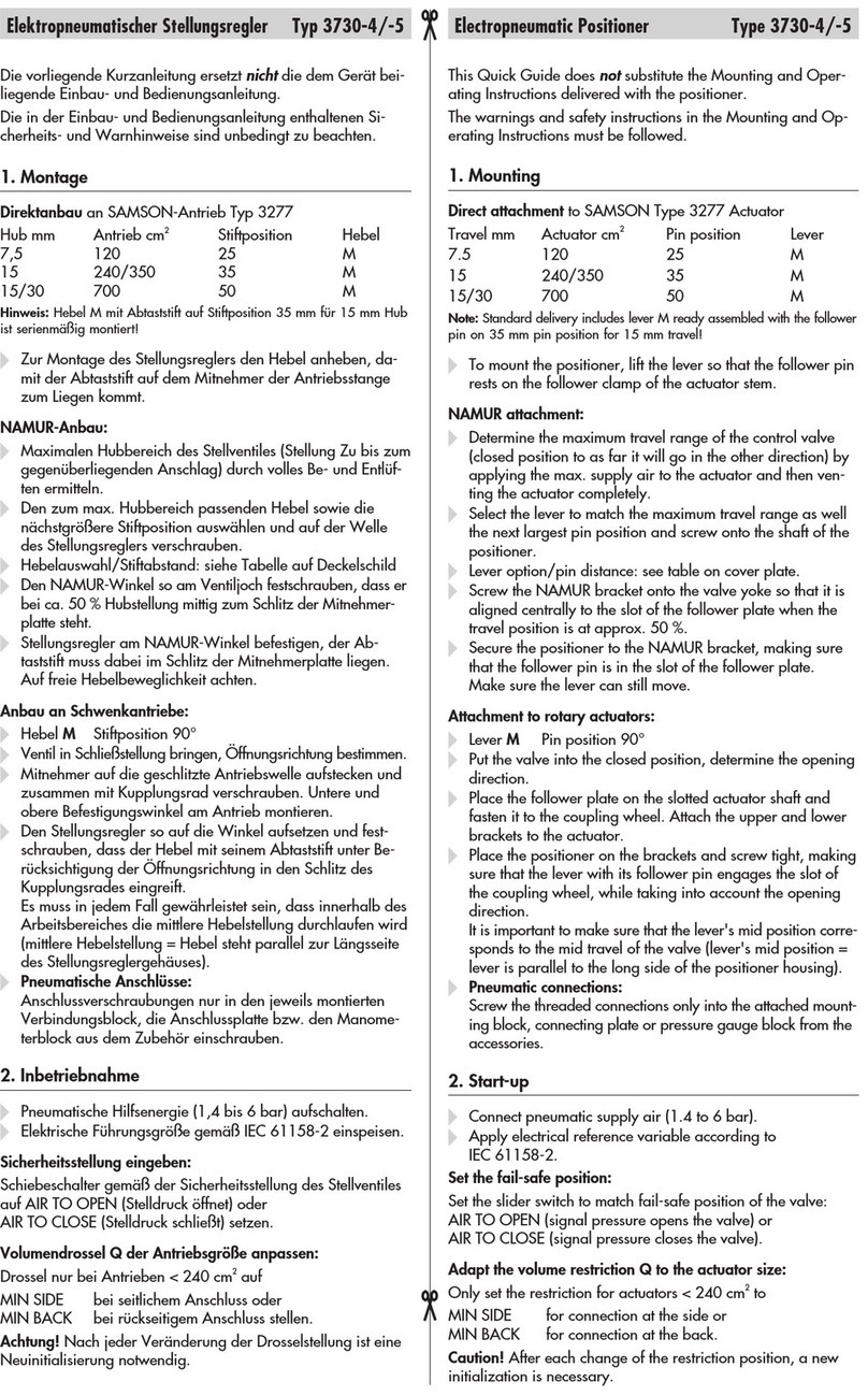
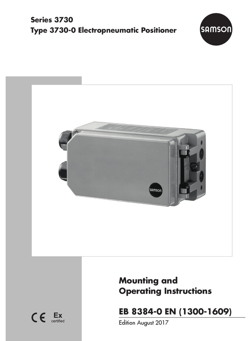
uEB8384-0
Ausgabe November 2017 KurzanleitungKA8384-0(1010-5919)
HubanDIP-SchalterS2undS3vorwählen
Stiftposition Hub bei Spanneneinsteller auf 0-Position
17 5,3 7, 5 10,6
25 5,3 7, 5 10,6 15
35 7, 5 10,6 15 21,2
50 10,6 15 21,2 30
70 15 21,2 30 42,4
100 21,2 30 42,4 60
200 42,4 60 84,8 120
ÎS2 = OFF ÎS2 = ON ÎS2 = OFF ÎS2 = ON
ÎS3 = OFF ÎS3 = OFF ÎS3 = ON ÎS3 = ON
VolumendrosselQanpassen(nurfürAntriebsächen<240cm²)
ÎMIN SIDE, bei seitlichem Anschluss
ÎMIN BACK, bei rückseitigem Anschluss
BewegungsrichtunganDIP-SchalterS4einstellen
> >, mit steigender Führungsgröße vergrößert sich der Ventilhub
< >, mit steigender Führungsgröße verringert sich der Ventilhub
> > < >
Sicherheitsstellung AIR TO OPEN ÎS4 = ON ÎS4 = OFF
Sicherheitsstellung AIR TO CLOSE ÎS4 = OFF ÎS4 = ON
Evtl.StelldruckanDIP-SchalterS5begrenzen
ÎS5 = ON (Stelldruck = 2,4bar)
Stellungsregleranschließen
ÎPneumatische Hilfsenergie (1,4 bis 7bar) aufschalten.
ÎEingangssignal (4 bis 20mA) anschließen.
ÎVentil in kleinen Schritten auffahren. Falls das Ventil zum Schwin-
gen neigt, Schalter S6 = ON, um die Verstärkung des Regelkrei-
ses zu verringern.
FührungsgrößeanDIP-SchalterS7undS8einstellen
4 bis 11,9mA 12,1 bis 20mA 4 bis 20mA
ÎS7 = OFF ÎS7 = ON ÎS7 = OFF
ÎS8 = OFF ÎS8 = OFF ÎS8 = ON
NullpunktundSpannenkorrektureinstellen
ÎSpanneneinsteller SPAN auf 0-Position stellen.
Î
Eingangssignal mit mA-Geber auf Stromwert (Führungsgröße)
einstellen.
Bewegungsrichtung > > > > > > < > < > < >
Führungsgröße1) [mA] 4…20 4…12 12…20 4…20 4…12 12…20
1)Eingangssignal fett gedruckt
Î
Nullpunkteinsteller ZERO drehen, bis sich die Kegelstange gerade
aus der Ausgangslage bewegt.
ÎEingangssignal gemäß „Ventil auf” einstellen, ggf. Hub mit Span-
neneinsteller SPAN anpassen.
Evtl.DichtschließfunktionanDIP-SchalterS9undS10aktivieren
Sicherheitsstellung
AIR TO OPEN
Sicherheitsstellung
AIR TO CLOSE Dreiwegeventil
ÎS9 = ON ÎS9 = OFF ÎS9 = ON
ÎS10 = OFF ÎS10 = ON ÎS10 = ON
Einzelheiten vgl. zugehörige Einbau- und Bedienungsanleitungen uEB8384-0
