1. Design and principle of operation
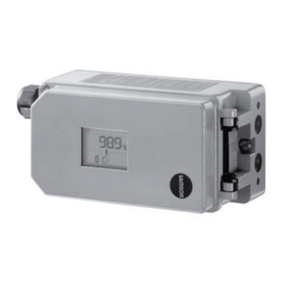
The positioner essentially consists of an in-
ductive, non-contact displacement sensor
system and an electrically controlled valve
block comprising the 2/2-way on-off valves
and an electronic unit. This unit contains
two microcontrollers for processing the con-
trol algorithm and managing the communi-
cation.
Whenever a deviation between the actual
valve travel (actual value) and the reference
variable (set point) occurs, the microcontrol-
ler produces binary pulse-pause modulated
signals to control the two 2/2-way on-off
valves, each of which is assigned an am-
plifier. One of these valves controls the
exhaust air, and the other one controls the
supply air.
The supply air valve (3) switches the supply
air (7, supply air pressure 1.4 to 6 bar) to
the actuator (filling). The exhaust air valve
(4) controls the air exhausted from the actua-
tor to the atmosphere (venting). These on-off
valves can either have the switching states -
permanently open, permanently closed - or
generate single pulses of changing widths.
With the two valves being controlled, the
plug stem moves to a position correspond-
ing to the reference variable. If there is no
system deviation, both the supply air and
the exhaust air valve are closed.
As a standard feature, the positioner is
equipped with a fault message output (bi-
nary output according to EN 60947-5-6)
used to signalize a fault to the control room.
Activating the write protection switch lo-
cated in the hinged cover prevents the posi-
tioner settings from being overwritten by the
HART protocol.
Forced venting function
The positioner is controlled via a 6 to
24 V signal, causing the signal pressure
to be applied to the actuator. If this volt-
age signal decreases, the signal pressure is
shut off and the actuator is vented. The
springs contained in the actuator move the
valve to its fail-safe position.
The forced venting function is installed in all
positioners from model index .03and up-
wards. The function can be activated or
deactivated by a switch. See chapter 4.2
(page 34) for more details.
1.1 Options
As a supplement to the standard positioner
version, there are several additional options
to extend the positioner functions.
Limit switches
To signalize the valves’ end positions in fail-
safe circuits, either two software limit swit-
ches or two proximity switches can be used.
Position transmitter
The position transmitter is an intrinsically
safe 2-wire transmitter controlled by the
microcontroller of the positioner. It serves to
assign the valve position with the 4 to 20
mA output signal. The position transmitter
signalizes both end positions, "valve closed"
or "valve fully open", as well as all inter-
mediate positions. Since the valve positions
are signalized to the positioner inde-
pendently of the input signal (minimum
current must be observed), the position
transmitter is a suitable option for checking
the current valve position.
10 EB 8380-1 EN
Design and principle of operation


