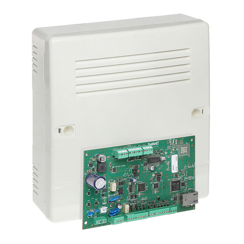
Satel Integra Series User manual
Other Satel Control Panel manuals

Satel
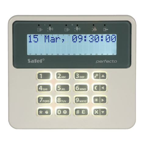
Satel PERFECTA User manual

Satel
Satel ACSP-402 User manual
Satel
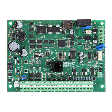
Satel CA10 plus User manual
Satel
Satel Integra Series User manual

Satel
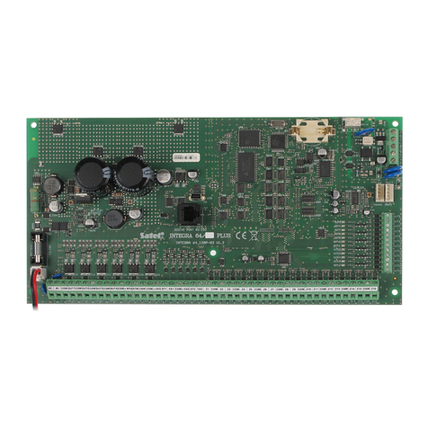
Satel Integra Series User guide
Satel
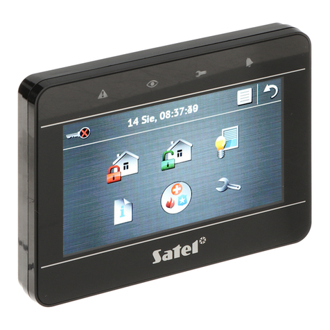
Satel Integra Plus Series User guide
Satel
Satel Versa Owner's manual

Satel
Satel Integra Series User manual

Satel
Satel INTEGRA User manual

Satel
Satel Integra 128-WRL Owner's manual
Satel
Satel PERFECTA-32-SET-A/IT User guide

Satel
Satel Integra 24 Owner's manual

Satel
Satel ACCO-NT User guide
Satel
Satel INTEGRA Plus User manual
Satel
Satel PERFECTA-IP-32 User guide
Satel
Satel Versa Seris User guide
Satel
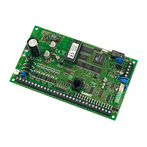
Satel CA-5 User manual
Satel
Satel CA-10 User guide

Satel
Satel CA-10 Owner's manual
Satel
Satel CA-10 Instruction manual
Popular Control Panel manuals by other brands

Mitsubishi Heavy Industries
Mitsubishi Heavy Industries SC-SL4-AE2/1 user manual

Sminn
Sminn BOX L VF1L EI instruction manual

Balboa
Balboa TP600 user manual

Nice
Nice HSCU1 Instructions and warnings for installation and use

Truma
Truma CP plus installation instructions

Crowcon
Crowcon Vortex Installation, operation and maintenance
