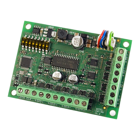
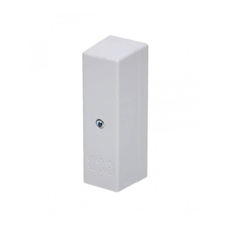
Satel INT-KNX-2 User manual

INT-KNX-2
KNX INTEGRATION MODULE
int-knx-2_en 03/15
The INT-KNX-2 module integrates the INTEGRA / INTEGRA Plus alarm system with the KNX
system. Using the module, the control panel can control the actuators connected to the KNX
bus, and the bus devices can control the alarm system. This manual applies to the module
with firmware version 2.00, which is supported by the INTEGRA and INTEGRA Plus control
panels with firmware version 1.13 of 2015-03-11 (or newer).
1 Features
64 KNX communication objects.
Expansion of the alarm system by adding virtual outputs dedicated to control the KNX
devices.
The number of virtual outputs determined by means of DIP switches (from 8 to 64 – a
multiple of 8).
Capability to control the KNX devices with macro commands.
Alarm system control by means of KNX devices (via the alarm system zones).
Bus Coupling Unit for direct connection of the module to the KNX bus.
NC type tamper input.
Connectable to RS-485 bus (firmware update through the bus).
2 Specifications
Supply voltage ................................................................................................... 12 V DC ±15%
Standby current consumption ..........................................................................................43 mA
Maximum current consumption........................................................................................50 mA
Environmental class according to EN50130-5 ......................................................................... II
Operating temperature range.............................................................................-10 °C...+55 °C
Maximum humidity.......................................................................................................... 93±3%
Dimensions ............................................................................................................. 80 x 57 mm
Weight................................................................................................................................. 32 g
The declaration of conformity may be consulted at www.satel.eu/ce

2 INT-KNX-2 SATEL
3 Electronics board
Fig. 1. Module electronics board.
Explanations to Fig. 1:
DIP-switches (see: DIP-SWITCHES).
STAT LED indicating the status of communication with the control panel:
ON – no communication with the control panel,
blinking – communication with the control panel OK.
KNX bus connectors.
button for future applications.
LED for future applications.
Description of terminals:
TMP - tamper input (NC) – if not used, it should be shorted to the common ground.
COM - common ground.
CLK - clock (expander communication bus).
DAT - data (expander communication bus).
+12V - +12 V DC power input.
A RS485 B - RS-485 bus.
4 DIP-switches
A numerical value is assigned to each switch. In OFF position, the value is 0. Numerical
values assigned to individual switches in ON position are shown in Table 1.
DIP-switch number 1 2 3 4 5 6 7 8
Numerical value 1 2 4 8 16 1 2 4
Table 1.

SATEL INT-KNX-2 3
The DIP-switches 1-5 are used for address setting. The sum of numerical values assigned
to switches 1-5 means the address set on the module. The address must be different from
that on the other modules connected to the communication bus of the control panel.
Switches 6-8 allow you to specify the number of outputs that will be added to the
system (they will be assigned to communication objects). The numerical value (see
Table 1) to which the desired number of outputs corresponds (see Table 2) must be set on
the switches.
Note: If the number of outputs set on the switches is higher than the available one, the
correct identification of the module by the control panel will be impossible. In order to
determine what number of outputs is available in the system, subtract the main board
outputs and the outputs in expanders connected to the control panel from the
maximum number of outputs supported by the panel.
Numerical value 0 1 2 3 4 5 6 7
Number of outputs 8 16 24 32 40 48 56 64
Table 2.
1 address is allocated for each group of 8 outputs on the expander bus. The module can
occupy up to 8 addresses on the expander bus. The control panel assigns consecutive
addresses to the module after the address set on the DIP switches. This should be taken into
consideration when designing the system and a sufficient number of free addresses should
be left. If the number of free addresses is insufficient, it will be impossible to properly
complete the identification procedure.
Fig. 2. Examples of the DIP switch setting. Example A: address 5, 8 outputs. Example B:
address 22, 32 outputs.
5 Installation
Disconnect power before making any electrical connections.
The expander is designed for indoor installation.
1. Fasten the module electronics board in the enclosure.
2. Using the DIP switches, set the appropriate address for the module and determine the
number of outputs that will be added to the system.
3. Connect the CLK, DAT and COM terminals to the corresponding terminals of the control
panel communication bus (see: installer manual for alarm control panel). It is
recommended that an unshielded non-twisted cable be used to make the connection. If
you use the twisted-pair type of cable, remember that CLK (clock) and DAT (data) signals
must not be sent through one pair of twisted conductors. The conductors must be run in
one cable.

4 INT-KNX-2 SATEL
4. If the module is to supervise the enclosure tamper contact, connect the wires of tamper
contact to the TMP and COM terminals. If the module is not to supervise the enclosure
tamper contact, connect the TMP terminal to the module COM terminal.
5. Connect the module to the KNX bus.
6. Connect the power leads to the +12 V and COM terminals. If the distance to the control
panel is less than 300 meters, the module can be supplied directly from the control panel.
If the distance to the control panel is higher, the module must be supplied from another
power source, which is located at a closer distance (a power supply unit or an expander
with power supply).
6 Module identification
The control panel does not support the modules which have not been identified, therefore
you must run the identification function after completion of the installation and power-up of
the alarm system. You can do it by means of:
LCD keypad: SERVICE MODE STRUCTURE HARDWARE IDENTIFICATION EXPANDERS ID.,
D
LOADX program: “Structure” window “Hardware” tab “Expansion modules” branch
“Exp. modules identification” button.
During the identification procedure, a number of outputs in the system, determined by means
of DIP switches, is assigned to the module, and additional addresses are allocated if the
number of outputs is greater than 8.
The control panel monitors presence of the identified modules. If the module is disconnected
from communication bus, position of DIP-switches is changed, or the device is replaced with
another one with DIP-switches set in the same way, a tamper alarm will be triggered.
7 Configuring the module
You can configure the module by means of the DLOADX program (version 1.13.008 or newer):
“Structure” window “Hardware” tab “Expansion modules” branch [module name].
Some of the parameters and options are stored in the control panel memory, and some of
them in the module memory. After clicking on the button in the main menu, the data
are only read from the control panel. Before you proceed to programming, the data must also
be read from the module. After clicking on the module name, the program may prompt you to
read these data. Otherwise, click on the “Read” button (see Fig. 3).
After programming is completed, click on the “Write” button to write the data to the module,
and on the button to write the data to the control panel.
7.1 Description of parameters and options
Name – individual name of the device (up to 16 characters).
Physical address – address of the INT-KNX-2 module.
KNX comm. delay after reset – the time that must elapse after starting the module, before
the module begins sending KNX telegrams.
Two level address – if the option is enabled, the address has a two-level structure. If the
option is disabled, the address structure is three-level.
Trouble if KNX bus disconnected – if the option is enabled, the module will report a trouble
after loss of communication with the KNX bus.
SATEL INT-KNX-2 5
No auto-reset after three module tamper alarms – if this option is enabled, the feature
reducing the number of tamper alarms from the module to three is disabled (the feature
prevents multiple logging of the same events and applies to successive uncleared alarms).
Tamper signaled in part. – partition where alarm will be triggered in the event of module
tamper.
Fig. 3. DLOADX program: configuring the INT-KNX-2 module.
7.1.1 Communication objects
Communication objects are presented in the table. Click on an object to configure its settings
in the panel on the right.
No. – number of the alarm system output assigned to the communication object. The output
can control the INTEGRA OUTPUT communication object. The field is blank if no output is
assigned to the communication object (see: DIP-SWITCHES).
Type/Name – type of the communication object and name of output / zone / macro command
(depending on the selected object type).
Group addresses – group addresses of the communication object.
Flags – each communication object has flags. The default flags should only be changed in
exceptional circumstances.
C– Communication
R– Read
W– Write

6 INT-KNX-2 SATEL
I– Read on init
T– Transmit
U – Update
Data type – size and meaning of the communication object data.
Priority – priority of the communication object.
Object type – type of the communication object:
none – communication object is not used.
Integra Output – change of output status changes the communication object value.
Integra Zone – change of communication object value changes the zone status.
Virtual (macro) – running the macro command changes the communication object value
(without involvement of virtual outputs). The macro command is a sequence of actions,
composed of single commands, which are to be done by the control panel when running
the macro command. The commands may include instructions to change the value of
INT-KNX-2 communication objects. Macro commands are offered by some of the
SATEL devices (e.g. INT-KSG, INT-TSG and INT-TSI keypads).
Parameters for communication object of INTEGRA OUTPUT type
Send on output ON – if the option is enabled, activating the output changes the object value
to that entered in the field below.
Send on output OFF – if the option is enabled, deactivating the output changes the object
value to that entered in the field below.
Cyclical transmmision period – time interval every which updated value of the
communication object is sent to the KNX bus. Value 0 means that the object value is not
cyclically sent.
Parameters for communication object of INTEGRA ZONE type
Zone no. – number of the alarm system zone whose status changes with the change of the
communication object value.
Reaction on "1" – zone reaction to the object value change to 1:
0. none – zone status will not change,
1: violation – zone will be violated,
2. restore – zone violation will end,
3. impulse – zone will be violated for 5 seconds.
Reaction on "0" – zone reaction to the object value change to 0 (0. none / 1: violation /
2. restore / 3. impulse).
On KNX bus rest. – zone reaction to the KNX bus power restore (0. none / 1: violation /
2. restore).
On KNX bus off – zone reaction to the KNX bus power loss (0. none / 1: violation /
2. restore).
On power up – zone status after starting the module (1: violation / 2. restore).
Parameters for communication object of VIRTUAL (MACRO) type
Name – name of the communication object for the purpose of creating macro commands (up
to 16 characters).
Value – value of the communication object after starting the module.
Cyclical transmmision period – time interval every which updated value of the
communication object is sent to the KNX bus. Value 0 means that the object value is not
cyclically sent.

SATEL INT-KNX-2 7
8 Updating the module firmware
Using the RS-485 bus, connect the module to the ACCO-USB converter, and then connect
the converter to the computer (see: ACCO-USB converter manual). You can find a program
for updating the module firmware and a detailed description of the firmware update procedure
on the www.satel.eu website.

SATEL sp. z o.o. • ul. Budowlanych 66 • 80-298 Gdańsk • POLAND
tel. + 48 58 320 94 00
www.satel.eu
Table of contents
Other Satel Control Unit manuals

Satel
Satel GPRS-T6 User manual

Satel
Satel INT-GSM User manual

Satel
Satel GPRS-T4 User manual

Satel
Satel ETHM-1 Plus User manual

Satel
Satel SATEL-TR49 SnapOn Quick setup guide

Satel
Satel ETHM-1 Plus User manual

Satel
Satel GSM-X User manual

Satel
Satel ETHM-1 User manual

Satel
Satel MST-1 User manual

Satel
Satel INT-KNX User manual