SATEL ACX-200 3
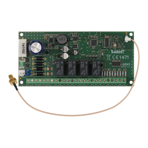
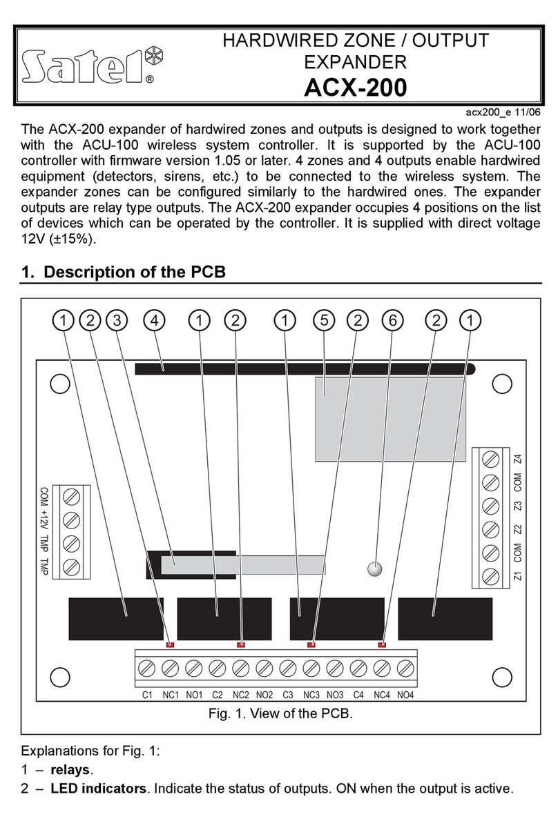
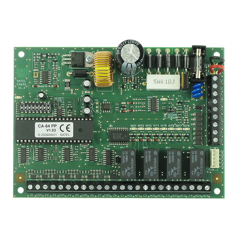
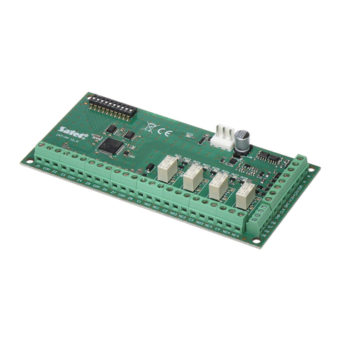
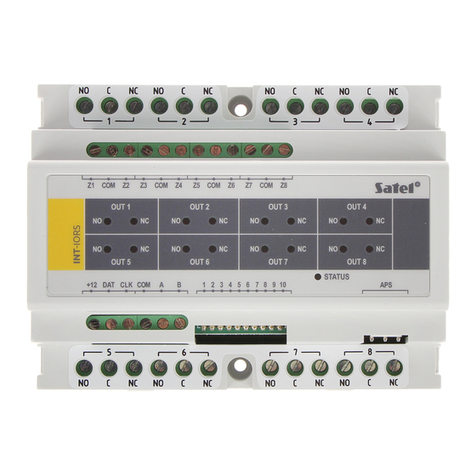
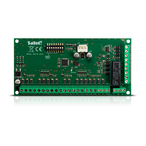
NO1...NO8 - relay output normally open contact.
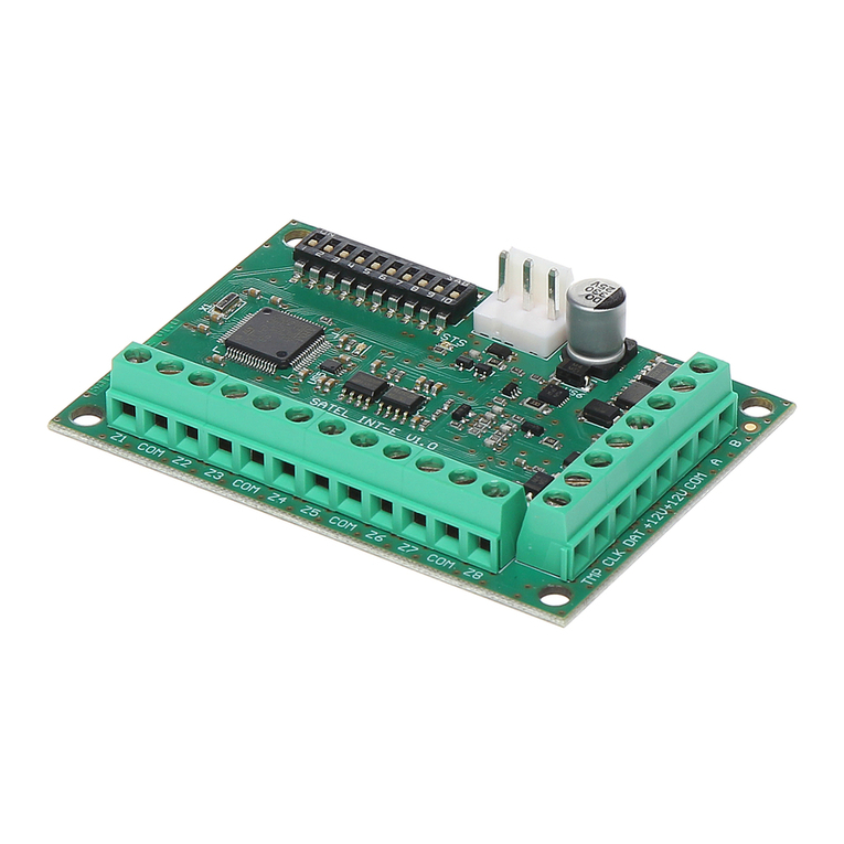
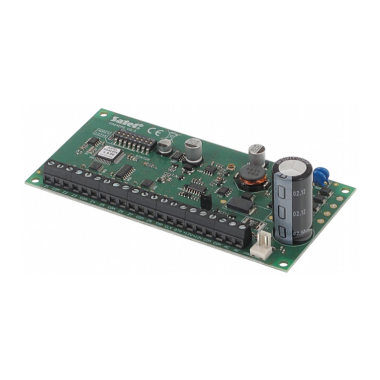
Z1…Z4 - zone.
4. Installation
Disconnect power before making any electrical connections.
The device is designed for indoor installation. It is recommended that the expander be
mounted high above the floor. This will allow you to get a better range of radio
communication and avoid the risk of the expander being accidentally covered by
people moving around the premises.
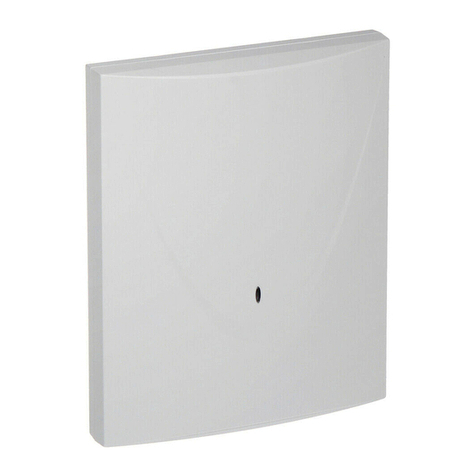
1. Loosen the cover locking screws and remove the enclosure cover.
2. Connect the temporary 12 V DC power supply to the expander and add the device
to the wireless system (see the ACU-100 / ACU-250 / ACU-120 / ACU-270
controller manual or the INTEGRA 128-WRL / VERSA / VERSA Plus control panel
installer manual). The sticker with 7-digit serial number which shall be entered
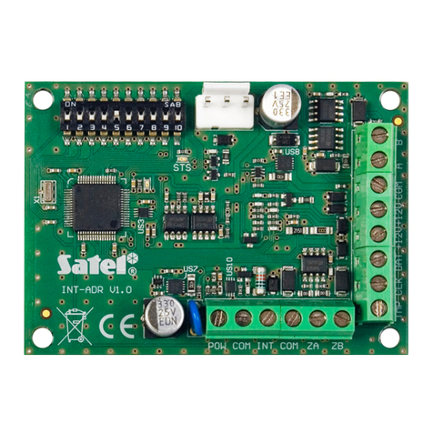
when registering the expander in the system can be found on the electronics
board.
3. Fasten the expander temporarily at the place of its future installation.
4. Check the level of signal received from the expander by the ACU-100 / ACU-250 /
ACU-120 / ACU-270 controller or the INTEGRA 128-WRL control panel. If the
signal level is lower than 40%, select another place for installation. Sometimes, it
is sufficient to shift the device ten or twenty centimeters to obtain a considerable
improvement in the signal quality.
5. Having checked that the selected location of installation ensures the optimum
level of radio signal, disconnect the temporary 12 V DC power supply.
6. Place the enclosure base against the wall and mark location of the mounting
holes.
7. Drill the holes in the wall for wall plugs (screw anchors).
8. Make an opening for wire harness in the enclosure base.
9. Run the wires through the opening made (power wires, cables connecting wired
devices with the expander, etc.).
10. Using wall plugs (screw anchors) and screws, secure the enclosure base to the
wall.
11. Connect detectors to the expander zones. For the EOL configuration, use a 2.2 k
resistor, and for the 2EOL configuration – two 1.1 kresistors.
12. If the tamper switch is to be supervised, connect the tamper output terminals to
the expander zone (you can connect the tamper output in parallel with the detector
and configure the expander zone as 2EOL).
13. Connect the devices to the expander outputs.
Note:Given the specific character of radio communication, it is not recommended that
the expander be used in applications where quick switchover of the output
status is expected.
14. Connect 12 V DC power wires to the +12V and COM terminals.
15. Replace the cover and then lock it with the screw.
