CA-64 ADR SATEL 5
INTEGRA control panel. Depending on the number of connected detectors with CA-
64 ADR MOD modules installed, and the addresses set in those modules, the control panel
will assign a specific number of zones in the system. This number is a multiplicity of number
8. Up to 48 zones are possible. The zone numbers are assigned to all expanders, based on
the bus addresses (from the lowest to the highest).
Notes:
•The INTEGRA 24 control panel enables the system to be expanded by up to 16
addressable zones. Addresses from the 0-15 range should be set in the CA-64 ADR MOD
modules.
•In case of the INTEGRA 32 control panel the system can be expanded by up to 24
addressable zones. Addresses from the 0-23 range should be set in the CA-64 ADR MOD
modules.
Example 1. Numbers of addressable zones - interaction of the CA-64 ADR expander with
INTEGRA 32 control panel.
2 LCD keypads (addresses 0 and 1) are connected to the keypad bus. All the keypad zones are used
in the system. CA-64 ADR expander with address 0 is connected to the expander bus. 20 detectors
with installed addressable modules are connected to the control panel by means of the expander (the
module addresses must be set within the ranges 0 to 15 and 20 to 23). Consequently, addresses 1
and 2 are additionally assigned to the CA-64 ADR expander. The system zones are numbered as
follows:
−1-8 – main board zones;
−9-24 – zones assigned to detectors with addressable modules installed (detector with address 0 –
zone 9; detector with address 1 – zone 10, etc., up to the detector with address 15 – zone 24);
−25-28 – zones assigned to the keypad zones;
−29-32 – zones assigned to the detectors with addressable zones installed (detector with address
20 – zone 29; detector with address 21 – zone 30, etc.).
In order to obtain continuity of addressable zones numbering, the LCD keypad addresses should be
changed to 2 and 3 (the keypad zones will be given numbers 29-32), and addresses 0-19 should be
set in the addressable modules (the zones assigned to detectors with addressable modules installed
will be given numbers 9-28).
Example 2. Numbers of addressable zones - interaction of the CA-64 ADR expander with
INTEGRA 128 control panel.
4 LCD keypads (addresses from 0 do 3) are connected to the keypad bus. All the keypad zones are
used in the system. Connected to the first expander bus are 2 CA-64 E expanders (addresses 0 and
1), 2 CA-64 EPS expanders (addresses 8 and 9), and CA-64 ADR expander (address 2). 48 detectors
with installed addressable modules are connected to the control panel by means of the expander (the
module addresses set within the range from 0 to 47). Consequently, addresses from 3 to 7 are
additionally assigned to the CA-64 ADR expander. The system zones are numbered as follows:
−1-16 – main board zones;
−17-24 – zones in CA-64 E expander with address 0;
−25-32 – zones in CA-64 E expander with address 1;
−33-80 – zones assigned to the detectors with addressable zones installed (detector with address 0
– zone 33; detector with address 1 – zone 34, etc.);
−81-88 – zones in CA-64 EPS expander with address 8;
−89-96 – zones in CA-64 EPS expander with address 9;
−113-120 – zones assigned to the keypad zones.
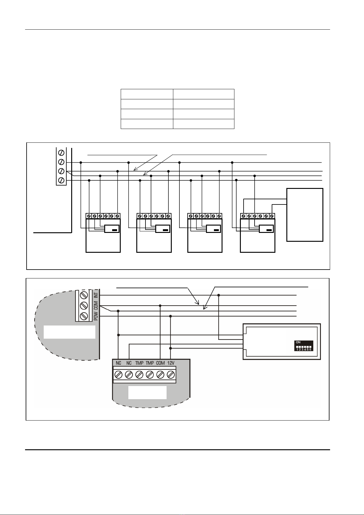
5. Connecting the addressable zones
It is recommended that all detectors and addressable modules be supplied from the POW
output. If the expander power supply capacity is too low, a separate power supply unit may