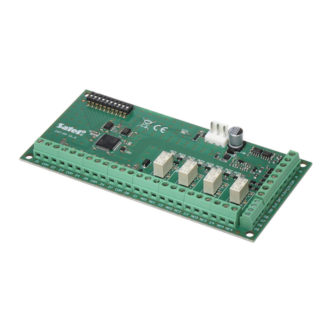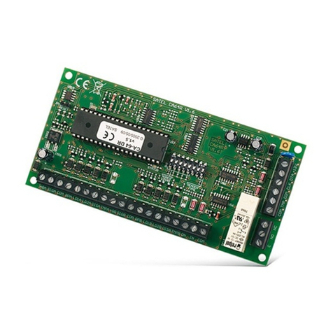
2 CA-64 EPS SATEL
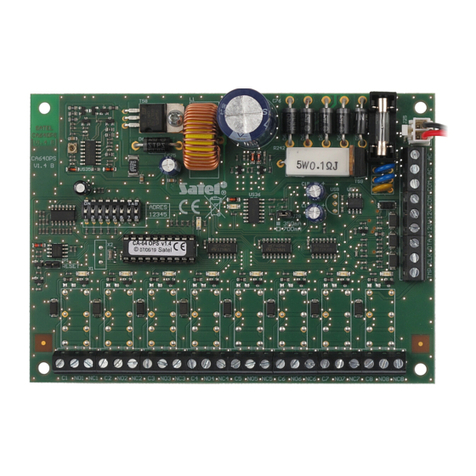
4 – leads to connect the battery (red +, black -).
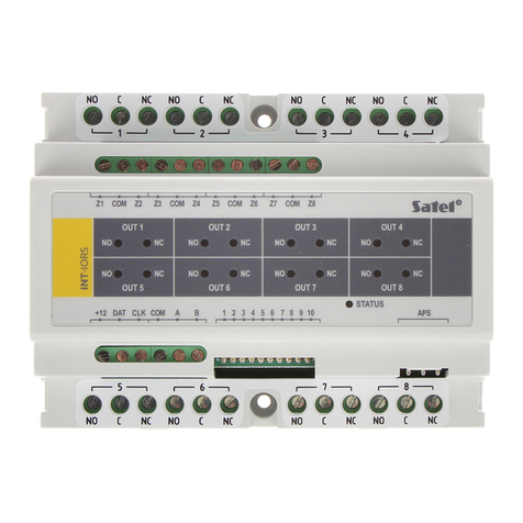
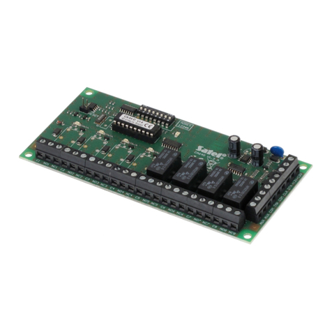
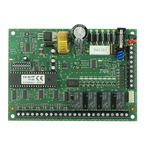
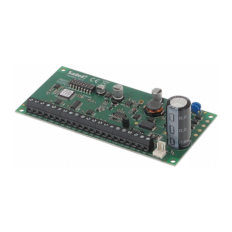
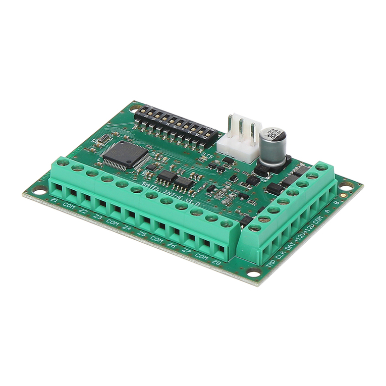
Description of the terminals:
Z1...Z8 - zones.
COM - common ground.
TMP - tamper input (if no tamper contact is connected to this terminal, it should be
shorted to common ground).
CLK - clock.
DTA - data.
+12V - power supply output. To the expander power supply unit may be connected
other electric energy consumers (e.g. detectors, modules with no power
supply). However, be careful not to cause an overload. It is advisable to
prepare the power supply load balance. The total of current inputs for all
consumers and battery charging current is not to exceed the capacity of power
supply unit.
AC - power supply input 18 V AC (from mains transformer secondary winding).
The minimum input voltage at the maximum load of the transformer by the
module must not drop below 16 V AC.
1.1 DIP-switches
The DIP-switches from 1 to 5 are to be used for address setting. The address must be
different from that of the other modules connected to the communication bus of alarm control
panel. In case of interaction with the VERSA control panel, an address from the 12 (0Ch) to
14 (0Eh) range must be set. In order to determine the expander address, add up the values
set on individual switches as shown in Table 1.
DIP-switch number 1 2 3 4 5
Numerical value
(for switch in ON position) 1 2 4 8 16
Table 1.
The switches 6 and 7 must be set to OFF position.
Position of the switch 8 affects the way of expander identification and availability of some
functions:
•OFF – the expander will be identified as CA-64 EPS. Support for the roller shutter motion
and vibration detectors, as well as programming the resistor value in EOL and 2EOL
configurations are not available.
The switch 8 must be in position OFF for the CA-64 control panel and for the
INTEGRA panels with firmware up to and including version 1.04.
•ON – the expander will be identified as CA-64 EPSi by the INTEGRA control panel with
firmware version 1.05 or newer, as well as by the VERSA control panels (identification of
the expander in the other panels will be impossible). Available are also support for roller
shutter motion and vibration detectors and programming the resistor values in EOL and
2EOL configurations (make sure that a suitable resistor value is programmed).
