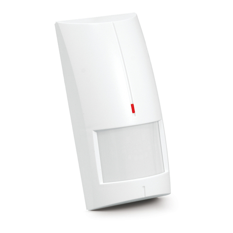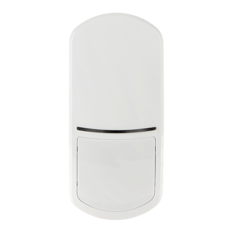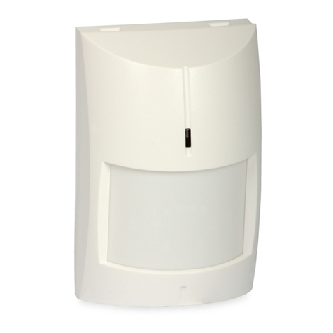
SATEL SILVER 3
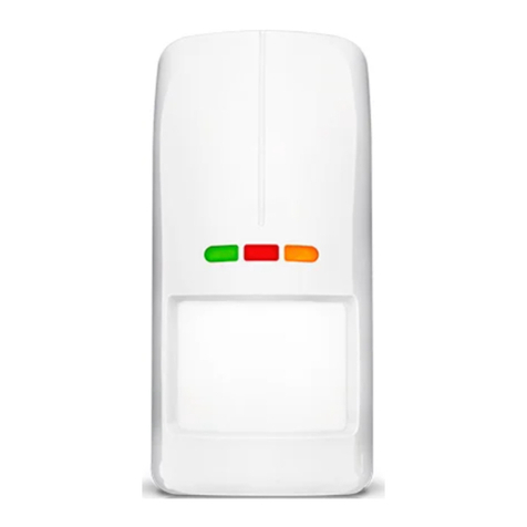
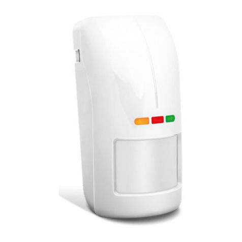
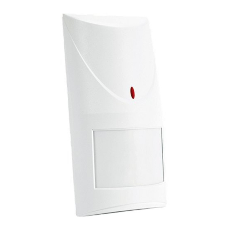
LED indicator
The LEDs indicate:
•warm-up – flashing alternately red and green for about 30 seconds;
•motion detected by one of the sensors – lights green for 2 seconds;
•alarm – lights red for 2 seconds;
•alarm memory – flashing red;
•trouble – lights red for entire duration of the trouble.
Enabling the LED by using a jumper
If you put a jumper across the LED pins as shown in Fig. 6, the LED will be enabled, i.e. it will
indicate the above described events (the LED can’t be enabled/disabled remotely). If you put
a jumper across the LED pins as shown in Fig. 7, the LED will be disabled, but it can be
enabled/disabled remotely.
Remote LED enable/disable
The LED terminal is provided to allow remote LED enable/disable. When the terminal is
connected to common ground, the LED is enabled. When the terminal is disconnected from
common ground, the LED is disabled.
If the detector is used in the INTEGRA / INTEGRA Plus alarm system, you can connect to
the terminal an OC type control panel output programmed e.g. as “Zone test status” or “BI
switch”.
Alarm memory
If the LED is enabled, the detector can indicate the alarm memory. The MEM terminal is
provided to allow the alarm memory enable/disable. The alarm memory is enabled, when the
terminal is connected to the common ground. The alarm memory is disabled, when the
terminal is disconnected from the common ground.
If the alarm memory is enabled and an alarm occurs, the LED will start flashing red.
Indication of the alarm memory will continue until the alarm memory is enabled again (the
MEM terminal is connected to the common ground). Disabling the alarm memory will not stop
the alarm memory indication.
If the detector is used in the INTEGRA / INTEGRA Plus alarm system, you can connect to
the MEM terminal an OC type control panel output programmed e.g. as “Armed status”.
3. Electronics board
Do not touch the pyroelectric sensor, so as not to soil it.
terminal blocks:
WRN - anti-mask output (NC relay).
TMP - tamper output (NC).
COM - common ground.
12V - power input.
NC - alarm output (NC relay).
LED - enable/disable the LED indicator.
MEM - enable/disable the alarm memory.
pins for configuration of the detector outputs. Available settings are shown in the figures:
2 – built-in resistors are used – connect the detector outputs as shown in Fig. 13 or
Fig. 14,
