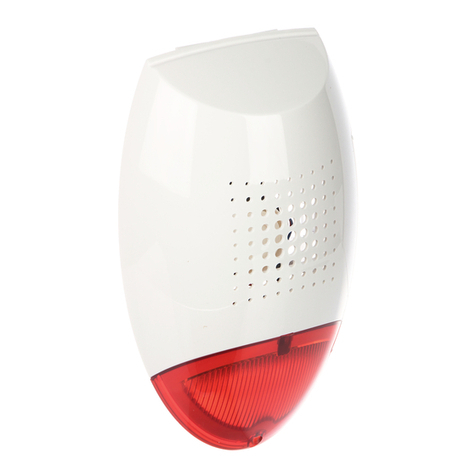
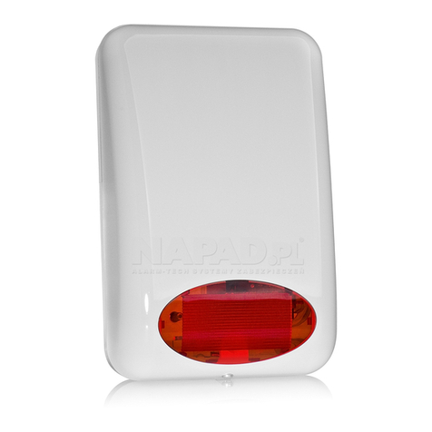
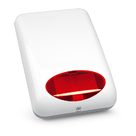
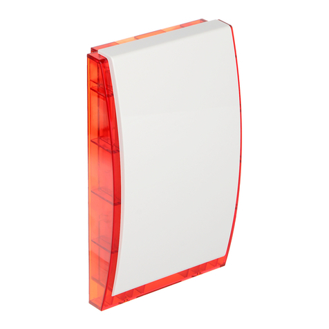
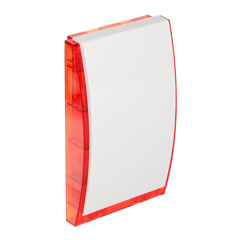
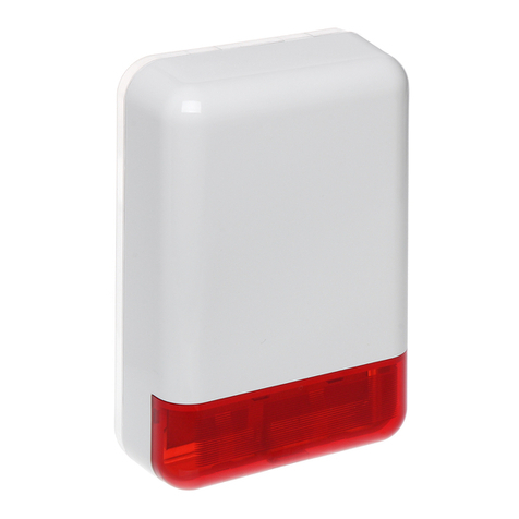
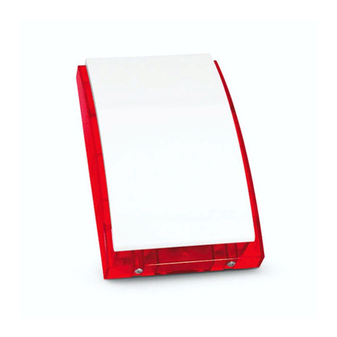
Satel SP-6500 User manual

®
SP-6500
SD-6000
OPTICAL-ACOUSTIC OUTDOOR SIREN
sp6500_en 03/13
The SP-6500 / SD-6000 siren provides information about alarm situations by means of
optical and acoustic signaling. The device is designed for outdoor installation.
1. Features
Acoustic signaling by means of piezoelectric transducer [SP 6500] or dynamic horn
[SD-6000].
Four selectable tones for acoustic signaling.
Selectable volume level of the acoustic signaling.
Capability of limiting the duration of acoustic signaling in accordance with local
regulations.
Optical signaling by means of LEDs.
Capability of using two LEDs as indicators and customize their functionality to the user's
needs.
Optional operation with a backup battery.
Weatherproofed electronic circuit.
Tamper protection in 2 ways – cover removal and tearing enclosure from the wall.
Inner cover of galvanized metal sheet.
High-impact polycarbonate enclosure, featuring a very high mechanical strength.
Hinged enclosure cover.
Selectable position of cover hinges.
2. Specifications
Supply voltage ................................................................................................... 12 V DC ±15%
Standby current consumption
SP-6500 ........................................................................30 mA
SD-6000 ........................................................................20 mA
Maximum current consumption (signaling)
SP-6500 ......................................................................150 mA
SD-6000 ......................................................................300 mA
Maximum current consumption (signaling + battery charging)
SP-6500 ......................................................................600 mA
SD-6000 ......................................................................900 mA
Sound pressure level (at 1 m distance) .................................................................up to 120 dB
Environmental class according to EN50130-5 ........................................................................IV

2 SP-6500 • SD-6000 SATEL
Operating temperature range............................................................................. -25C …+70C
Maximum humidity ..........................................................................................................93±3%
Dimensions ................................................................................................. 230 x 230 x 65 mm
Weight
SP-6500 .......................................................................1160 g
SD-6000 .......................................................................1530 g
The declaration of conformity may be consulted at www.satel.eu/ce
3. Description
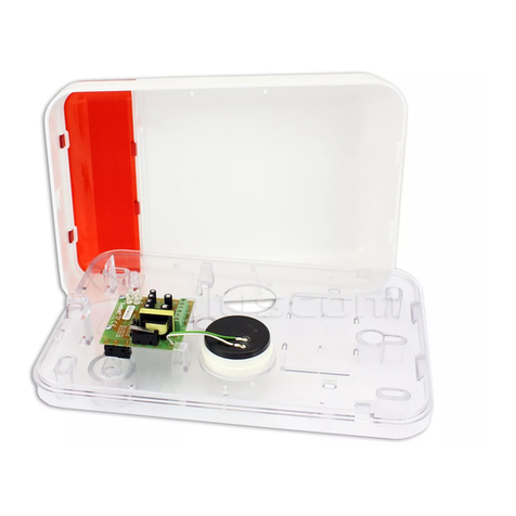
Fig. 1 shows the SP-6500 siren with cover open:
enclosure base.
piezoelectric transducer (in the SD-6000 siren, a dynamic horn is installed at the same
place).
tamper switch.
battery mounting holders.

SATEL SP-6500 • SD-6000 3
battery connection leads (red +, black -).
electronics module.
inner metal cover.
enclosure cover.
Triggering the alarm signal
The signaling is triggered when +12 V DC or 0 V voltage is removed from the STA input
(acoustic signal) or the STO input (optical signal). The way of triggering the signal is set by
means of the POLARITY A pins (acoustic signal) and the POLARITY O pins (optical signal).
Duration of the acoustic signaling is limited (LIMIT SIGN. or TIME 0 and TIME 1 pins).
Note: For the SATEL alarm control panels, the OC type low current outputs can be used to
trigger the signaling (as well as to control the LED input). Reverse polarity must be
programmed for these outputs.
Delay of the triggering the alarm signal
The signaling can be triggered, if +12 V DC or 0 V voltage has been applied to the STA input
for 30 seconds since powering up the siren. Such a delay will prevent the signaling from
being accidentally triggered during installation work. The siren indicates by rapid blinking of
the two LEDs that the alarm signaling cannot be triggered.
If the signaling must be triggered for test purposes immediately after start-up of the siren,
skipping the 30-second delay, do as follows:
1. Remove the jumper from INT/EXT LED pins before powering up the siren.
2. Power up the siren.
3. Place the jumper to the INT/EXT LED pins within 5 seconds.
Main power supply
The siren must be supplied with 12 V DC ±15% voltage.
Backup power supply
A 12 V / 2.3 Ah lead-acid battery can be used as a backup power supply.
Main power failure
If a battery is installed in the siren, the alarm signaling will be triggered in the event of main
power failure:
the optical signaling will continue until the 12 V DC power supply is restored;
duration of the acoustic signaling depends on how the siren is configured (LIMIT SIGN. or
TIME 0 and TIME 1 pins).
Terminals
+12V - power input. Connect it to the control panel output serving as the +12 V DC power
output.
COM - common ground. Connect it to the control panel common ground.
STA - input to trigger the acoustic signal. Connect it to the suitably programmed output of
the control panel.
STO - input to trigger the optical signal. Connect it to the suitably programmed output of
the control panel.

4 SP-6500 • SD-6000 SATEL
LED - input to control the LEDs used as indicators / to reset the acoustic signaling
limiting function. Connect it to the suitably programmed output of the control panel
(e.g. armed status indicator).
TMP - tamper output (NC). Connect one terminal to the control panel zone programmed
as tamper, and the other to the control panel common ground.
STMP - tamper input – the siren tamper switch is connected to the terminals.
SP - terminals to which the piezoelectric transducer [SP-6500] or dynamic horn
[SD-6000] is connected.
Siren configuration pins
- jumper on; - jumper off
LED INT/EXT
Allow you to set how the LEDs used as indicators are to be controlled.
The LEDs used as indicators show that power supply is available (inner control).
The LEDs used as indicators are controlled by means of the LED input (outer
control). FLASH/LIGHT
Allow you to set how the LEDs used as indicators are to operate.
The LEDs used as indicators are blinking when active.
The LEDs used as indicators are lit when active.
2LED/1LED
Allow you to set the number of LEDs used as indicators.
The indicator function is performed by two LEDs.
The indicator function is performed by one LED.
LOUDNESS H/L
Allow you to set the acoustic signal volume.
Maximum loudness of the acoustic signal.
Normal loudness of the acoustic signal.
LIMIT SIGN.
Allow you to enable / disable the acoustic signal limiting function. When the function is
enabled, the status of TIME 0 and TIME 1 pins is ignored, the acoustic signaling lasts up to
60 seconds and can only be triggered 3 times (a time of at least 40 seconds must elapse
between the consecutive alarms). The alarm counter will be reset after the LED input status
is changed (the LED input polarity being irrelevant).
The acoustic signal limiting function is enabled.
The acoustic signal limiting function is disabled.
TIME 1 TIME 0
The two pairs of pins allow you to set the cut-off time of acoustic signaling.
1 minute.
5 minutes.

SATEL SP-6500 • SD-6000 5
10 minutes.
15 minutes.
MELODY 1 MELODY 0
The two pairs of pins allow you to select the tone type.
Two sound frequencies (1450 Hz/2000
second.
Hz) alternating within 1
Sound with rising frequency (from 1450 Hz to 2000 Hz) within 1
second.
Sound with smoothly rising and falling frequency (1450 Hz –
2000 Hz – 1450 Hz) within 1 second.
Sound with falling frequency (from 2000 Hz to 1450 Hz) within
second.
1
POLARITY A
Allow you to set polarity for the STA input.
Acoustic signaling oved (inactive status:
+12 V DC voltage
is triggered w voltage is rem
is applied to the input).
hen +12 V DC
Acoustic signaling is triggered when 0 V voltage is removed (inactive status: 0 V
voltage is applied to the input). POLARITY O
Allow you to set polarity for the STO input.
Optical signaling i ved (inactive status:
+12 V DC voltage
s triggered wh oltage is remo
is applied to the input).
en +12 V DC v
Optical signaling is triggered when 0 V voltage is removed (inactive status: 0 V
voltage is applied to the input).
POLARITY LED
Allow you to set polarity for the LED input.
The LEDs used a ge is removed (inactive
status: +12 V DC
s indicators a 2 V DC volta
voltage is applied to the input).
re active when +1
The LEDs used as indicators are active when 0 V voltage is removed (inactive
status: 0 V voltage is applied to the input).
inges
sure cover and base are connected with hinges. The hinges are of the detachable
h enables the cover to be fully removed. The moving parts of hinges can be
H
The enclo
type, whic
mounted in any position, thus allowing you to select whether the cover is to open downward,
to the left or to the right. According to the standard factory execution, the cover opens
downward. How to relocate the moving parts of hinges – see section M
OUNTING THE HINGES IN
OTHER THAN STANDARD FACTORY POSITION
.

6 SP-6500 • SD-6000 SATEL
Enclosure base
Explanations for Fig. 2:
mounting hole.
cable entry hole.
tamper mounting hole.
4. Installation and start-up
Power down the control panel before connecting the siren to it.
The siren must be installed on the wall, high above the floor, at a hard to access location, so
as to minimize the risk of tampering.
1. Undo the cover locking screw (you do not have to remove it completely) and, holding the
cover by its edge, pull it open (Fig. 3 shows how the cover should be opened, when the
hinges are mounted in standard factory position).
2. Remove the cover.
3. Move aside the catches holding the electronics module and remove it.

SATEL SP-6500 • SD-6000 7
4. Place the enclosure base on the wall and mark the location of mounting holes (see
Fig. 2). Be sure to take into account the tamper mounting hole.
5. Drill the holes for wall plugs (screw anchors).
6. Run the wires through the hole in the enclosure base (see Fig. 2)
7. Using wall plugs (screw anchors) and screws, fasten the enclosure base to the wall (the
wall plugs and screws are included in the siren delivery set).
8. Secure the electronics module in the enclosure base.
9. Connect the siren terminals with wires to the control panel terminals.
10.Using jumpers, configure the siren.
11.If a battery is to be installed in the siren, secure the battery with the holders provided for
this purpose, and then connect leads to the battery (the red lead to the positive terminal,
the black lead to the negative terminal). After connecting the battery, two LEDs will start
blinking rapidly.
12.Replace the siren cover, close the cover and then lock it with the screw.
13.Power on the control panel. When the two LEDs stop blinking rapidly, you can test the
siren for correct functioning. In order to test the siren you can use the output test function,
which is available in some control panels, or you can trigger an alarm for testing
purposes.
Mounting the hinges in other than standard factory position
If the cover is to open in other direction than the standard factory one, open the cover and:
1. Detach the hinges and remove the cover.

8 SP-6500 • SD-6000 SATEL
2. Remove the moving parts of the hinges (see Fig. 4 and Fig. 5).
3. Insert the moving parts of hinges in the holders on the left-hand side (to open the cover to
the right) or on the right-hand side (to open the cover to the left – see Fig. 6 and Fig. 7).
SATEL sp. z o.o. • ul. Schuberta 79 • 80-172 Gdańsk • POLAND
tel. + 48 58 320 94 00
www.satel.eu
This manual suits for next models
1
Table of contents
Other Satel Security System manuals

Satel
Satel ASP-105 Technical manual

Satel
Satel MSP-300 User manual

Satel
Satel ABAX 2 User manual

Satel
Satel SP-4004 User manual

Satel
Satel SPL-2030 User manual

Satel
Satel SILVER User manual

Satel
Satel APD-200 User manual

Satel
Satel ASP-100 User manual

Satel
Satel MICRA User manual

Satel
Satel SPW-150 User manual

Satel
Satel Versa User manual

Satel
Satel SPLZ-1011 User manual
Satel
Satel SPL-5020 User manual

Satel
Satel SP-500 User manual

Satel
Satel ABAX 2 ASP-200 User manual
Satel
Satel SPL-5010 User manual

Satel
Satel Micra MSP-300 User manual
Satel
Satel ASP-205 User manual

Satel
Satel WZ-100 User manual

Satel
Satel SD-3001 R User manual