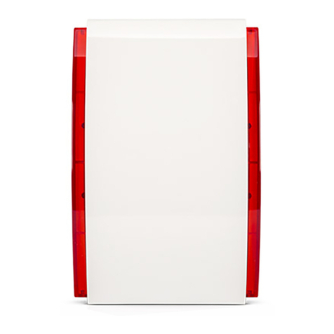
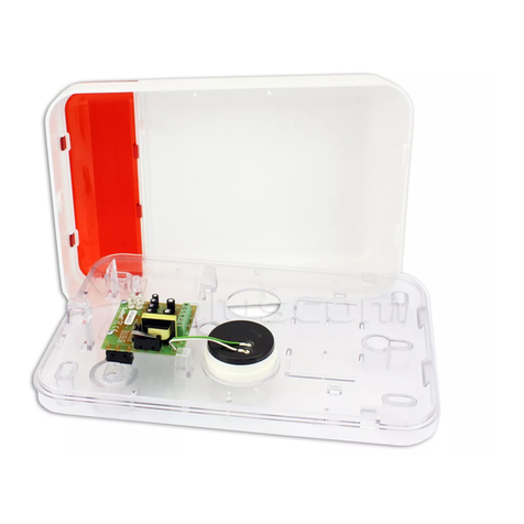
Satel SP-500 User manual
Other Satel Security System manuals

Satel
Satel MSP-300 User manual
Satel
Satel SPL-5010 User manual
Satel
Satel ROP-101/EU User manual
Satel
Satel ASP-201 User manual
Satel
Satel ASP-205 User manual
Satel
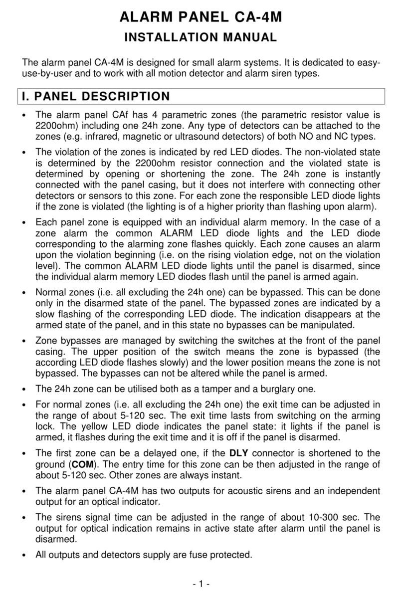
Satel CA-4M Operating and maintenance instructions

Satel
Satel Integra 24 User guide

Satel
Satel SOW-300 Series User manual

Satel
Satel SP-4001 User manual
Satel
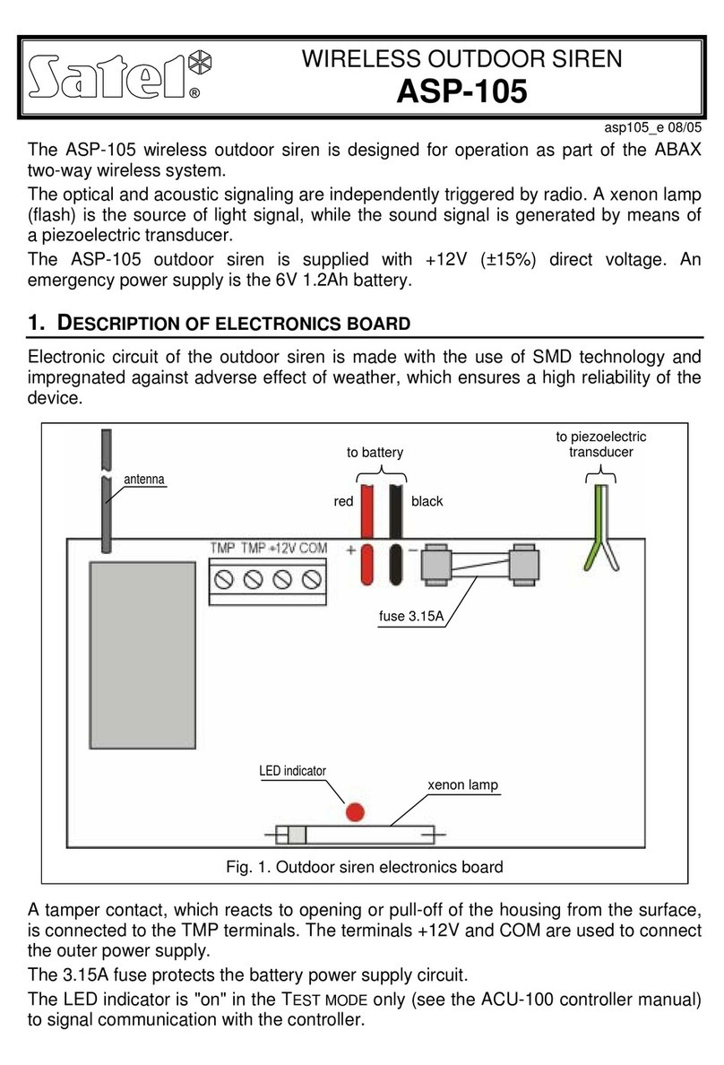
Satel ASP-105 Technical manual
Satel
Satel CSP-204 Installation manual

Satel
Satel ECAM22 User manual

Satel
Satel SPW-150 User manual
Satel
Satel SILVER User manual
Satel
Satel ASP-105 User manual
Satel
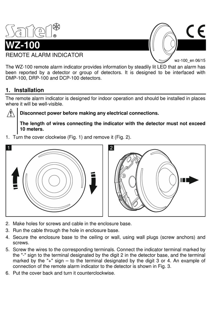
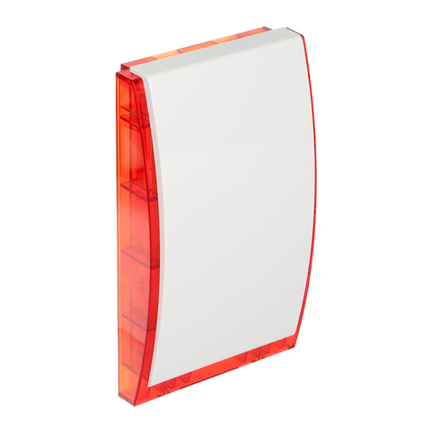
Satel WZ-100 User manual
Satel
Satel ASP-100-R User manual

Satel
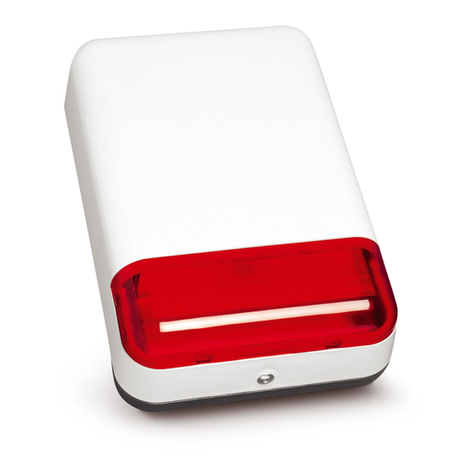
Satel SPL-5010 User manual
Satel
Satel SPL-2030-R User manual
Satel
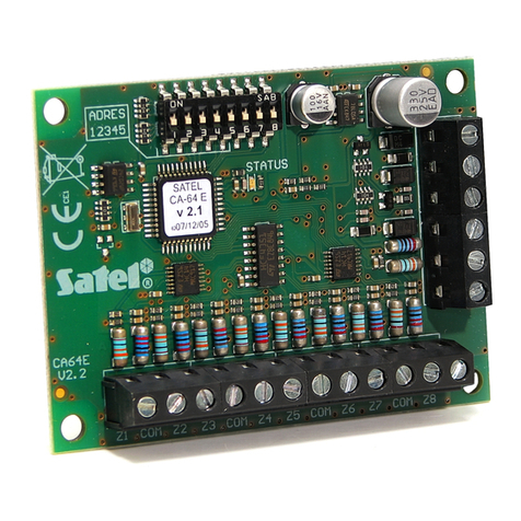
Satel CA-64 E User manual
Popular Security System manuals by other brands

Inner Range
Inner Range Concept 2000 user manual

Climax
Climax Mobile Lite R32 Installer's guide

FBII
FBII XL-31 Series installation instructions

Johnson Controls
Johnson Controls PENN Connected PC10 Install and Commissioning Guide

Aeotec
Aeotec Siren Gen5 quick start guide

IDEAL
IDEAL Accenta Engineering information

Swann
Swann SW-P-MC2 Specifications

Ecolink
Ecolink Siren+Chime user manual

Digital Monitoring Products
Digital Monitoring Products XR150 user guide

EDM
EDM Solution 6+6 Wireless-AE installation manual

Siren
Siren LED GSM operating manual

Detection Systems
Detection Systems 7090i Installation and programming manual
