2 SATEL SP-4001
3. CONNECTION
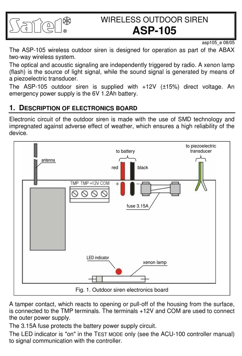
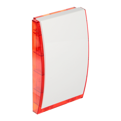
The SP-4001 siren can work with any alarm signal source where in the event of alarm condition
12V direct voltage appears on the signaling output(s). Acoustic signaling is triggered with 12V
power supply connected to the "+ SA -" terminals, and optical signaling – with power connected to
the "+ SO -" terminals. It should be borne in mind that the current capacity of the control panel
alarm and/or power outputs must ensure proper operation of the siren.
The siren tamper circuit is a safeguard against removal and detachment from the wall of the outer
housing. For the pull-off protection to function properly, the "S" element (Fig. 1) must be screwed
down to the mounting surface.
The "TMP" terminals are used to connect the siren to
the security system tamper circuit, while the
SENS.TMP terminals are provided for connecting the
inner sensor for tamper protection of the housing
against opening and/or pull-off.
The JP1–JP5 jumpers are intended for selection of
the siren audible signal (Fig. 2).
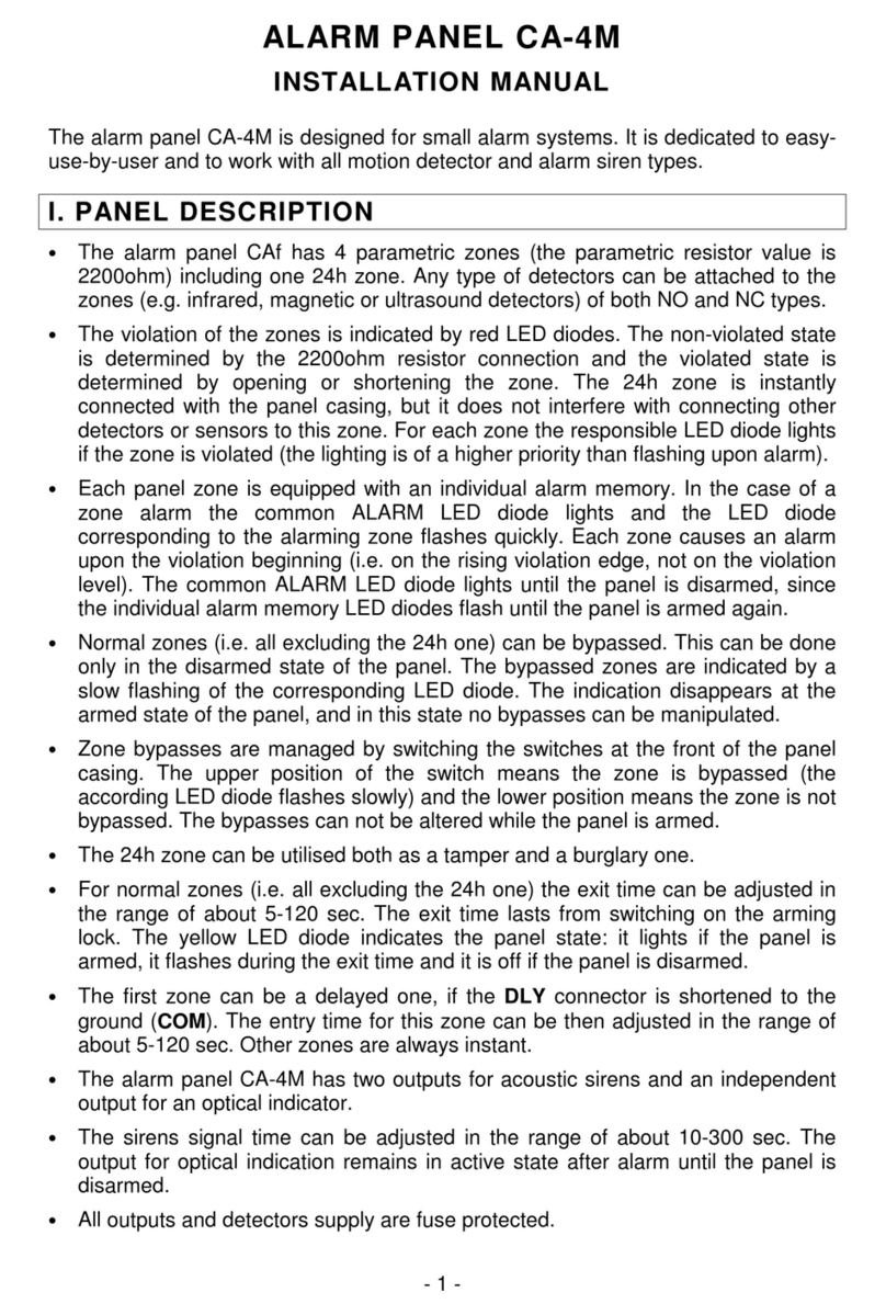
Both types of signaling can be managed from one control panel output if the contacts are
connected in parallel i.e. „+SA” with „+SO” and „-SA” with „-SO”.
Some control panels may require that a resistance R(approx. 1kΩ) be connected in the siren.
Otherwise, the siren will be gently buzzing when switched off.
4. TECHNICAL DATA:
Supply voltage ...........................................................................................................12V DC ±15%
Current consumption – acoustic signaling............................................................................. 200mA
Average/max. current consumption – optical signaling....................................................350/500mA
Average current consumption (SA, SO inputs connected in parallel)..................................... 550mA
Sound intensity...........................................................................................................approx. 120dB
Working temperature.................................................................................................. -35°C...+55°C
Dimensions ..............................................................................................................148x254x64mm
Weigh........................................................................................................................................885g
SATEL sp. z o.o.
ul. Schuberta 79
80-172 Gdańsk
POLAND
tel. (+48 58) 320 94 00
www.satel.pl
Latest EC declaration of conformity and
product approval certificates can be
downloaded from Web site
www.satel.pl
OUT1 – high-current output which triggers the
acoustic alarm signaling by direct
supply of +12V voltage to the +SA
terminal.
OUT2 – OC type low-current output which
triggers the optical alarm signaling by
shorting the +SO terminal to +12V
(via a relay).
RELAY
+SO -+SA -TMP TMP SENS.TMP
TO TAMPER CIRCUIT
AC AC OUT1 COM OUT2 OUT3 COM +12V
ALARM CONTROL PANEL (example)
Fig 3. Example of SP-4001 siren connection to control panel outputs (high- and low-current)
SP-4001 SIREN
SO –optical signaling
SA –acoustic signaling
TMP –tamper circuit
SENS.TMP –tamper sensor
JP1 melody 1 = JP1+JP4
JP2 melody 2 = JP2+JP5
JP3 melody 3 = JP3+JP5
JP4
JP5 Figure 2. Jumper settings
R

