Satel SD-3001 User manual

®
VISUAL – ACOUSTIC SIREN
SD-3001
sd3001_e 11/05
1. General
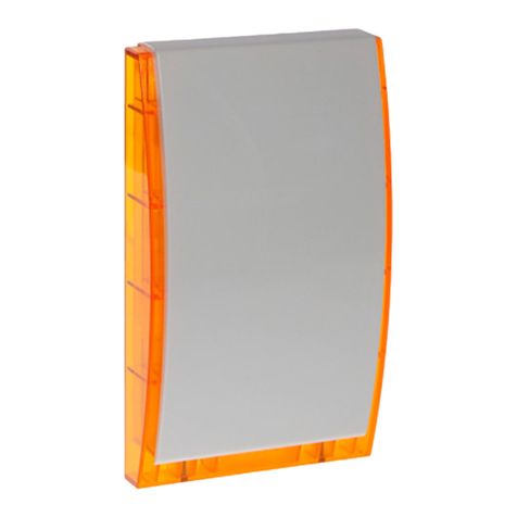
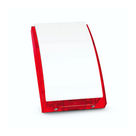
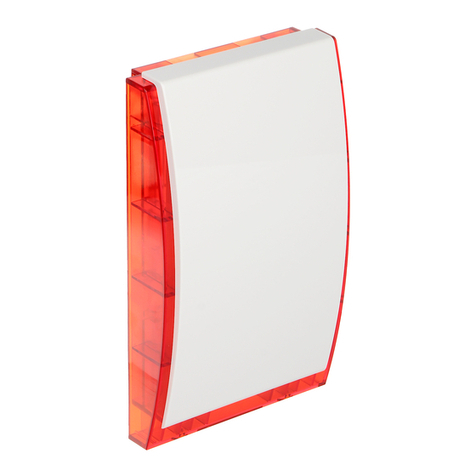
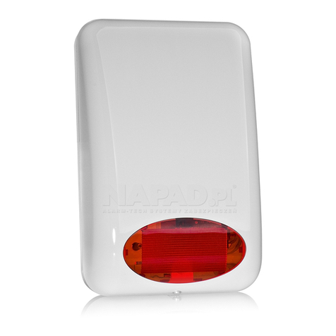
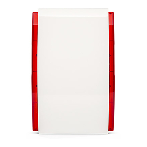
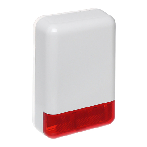
The SD-3001 outdoor visual-acoustic siren is designed for use in burglary and assault signaling
systems. The signaling function is performed in two ways: visually (by red color lamp blinking)
and acoustically (by a modulated, high-volume sound signal). A xenon lamp (flash) is the source of
light, while the sound signal is generated by means of a magnetodynamic transducer. The design of
the siren housing, as well as the inner enclosure made from galvanized sheet, ensure a high degree
of tampering protection (against opening, tearing off from the base, etc.). The electronics board is
made in Surface Mount Technology (SMT) and protected by impregnation against unfavorable effects
of weather conditions, thus ensuring high reliability of the equipment. The SD-3001 external housing
is made of the highly impact resistant PC LEXAN polycarbonate, hence it features a high mechanical
strength and guarantees aesthetic
The mechanical tamper switch can be replaced with a hermetic reed-relay switch. This enables the
tamper protection to be customized. The reed-relay switch is not included in the standard outfit of the
siren (i.e. it is sold separately).
2. Installation
Figure 1. View of the siren housing (back part).
In order to use the reed relay switch, it is necessary to dismount the mechanical switch installed by
the manufacturer on the „S” element and replace it with the new switch. This operation requires
resoldering of two wires which connect the switch with the siren electronics.
The SD-3001 siren should be mounted on a flat base in a location as inaccessible as possible to
minimize the tampering risk. The siren is to be attached to the base by means of screws and
expansion bolts.
Note:It is necessary to keep a clearance of approx. 0.5 cm between the upper edge of siren housing
and the ceiling or other obstacle limiting the mounting position from above. The lack of such
clearance can make the mounting of housing difficult.
soldering points
PCB
SIREN
mounting holes
cable entry
tamper circuit „S”
element
„S” element mounting hole
water drain hole
DO NOT PLUG !!!
Reed relay
switch
mounting screw

SATEL SD-3001
2
The tamper circuit of the siren protects the device against removal of housing or tearing the device off
the wall. Both these actions activate the alarm system. For the circuit to operate correctly the „S”
element must be screwed to the base. Special precautions are to be taken while screwing this
element, so as not to rupture.
After installing the siren, it is recommended to seal the mounting holes and the cable entries with
silicone compound.
3. Description of siren
The way of activating the SD-3001 siren is different from that of the SD-3000 unit (read
carefully the text below).
The SD-3001 siren can operate with any source of alarm signal. The circuits for acoustic and visual
signaling have separate control inputs. The acoustic signaling is controlled by the STA input, while the
visual signaling - by the STO input. Signaling is triggered after a change of voltage polarity from 0V to
12V or from12V to 0V.
Note:Alarm will be triggered also in case of stable signal loss at control input, e.g. after cutting off the
cable.
The way of changing the voltage polarity for the purpose of triggering the alarm is set by means of the
jumpers PLA and PLO.
The siren has been designed so as to be inactive right after power supply is connected to it,
irrespective of the status of inputs STA and STO. Only after elapse of 20 seconds in the stable,
inactive state (constant power supply from the control panel and input signals which does not
generate alarm) it is possible to trigger the signaling. After each switching the power supply off and
on, the time is counted over again. This function allows an accidental activation of the siren to be
avoided during installation of the system.
The test mode makes it possible to activate signaling without the necessity of waiting 20 seconds. In
order to do so, remove the jumper O+A, switch the supply voltage on and, within 5 seconds, put the
jumper on again.
The TMP terminals are used for connecting the siren to the tamper circuit of the alarm system. When
the siren is correctly mounted and the contacts of the switch placed on the „S” element are closed, the
TMP terminals are also shorted.
The siren is adopted for operation either without or with a battery installed (back-up power supply).
Where the battery is installed, the power supply voltage should be approx. +13.8V to provide correct
battery charging.
Power supply voltage should be connected to the terminals +12V and COM. The loss of voltage on
these terminals (with the battery connected) will trigger the tamper alarm, the duration of which
depends on the settings of jumpers TM0 and TM1. The kind of signaling is set with the jumper O+A.
Restoration of the supply voltage will cancel the tamper alarm. Having mounted the siren, check the
performance of this function by disconnecting and reconnecting the power supply voltage.
Note: The jumpers TM0, TM1 determine the maximum active time of acoustic signaling. Afterwards,
irrespective of the value set on the control panel, the siren will go silent. Signaling can only be
triggered again after the STA input voltage returns to the state corresponding to the PLA jumper
setting - that there is no alarm.
The LED placed on electronics board blinks when the +12V input power voltage is applied. The LED
can be switched off by removing the JP8 jumper.
The bulb 12V/5W connected to the separate terminals on the electronics board is a part of the battery
charging current limiter - the lamp is off during normal operation, but it glows when the battery is being
charged and in siren with own battery, also after the power supply from the control panel is lost.
4. Connection
There are two types of alarm outputs which are used in alarm control systems: common ground
outputs and common supply outputs. The siren can be activated by any type of output, provided that
suitable connections are made. If the control panel alarm outputs have no resistors which induced
polarization, then, in order to ensure proper operation of the siren, it is necessary to connect 2,2kΩ
SD-3001 SATEL 3
resistors as shown in Figure 2, 3 or 4 (depending on the output type). They can be connected in the
control panel or in the siren. Such resistors must also be connected for outputs with load control.
ML0
ML1
PLA
PLO
TM0
TM1
O+A
normalna polaryzacja wyjścia typu OC w centrali (zwarte do masy, gdy jest aktywne)
pozostałe zworki: ustawienie dowolne
Wyjścia OUT5 i OUT6
zaprogramowane jako
R - rezystor polaryzujący
(dla CA-6 - OUT4 i OUT5)
alarmowe (typu BURGLARY)
wyzwalanie sygn. akustycznej
COMOUT
CA-10 (CA-6)
+12V
TMP TMP
wyzwalanie sygn. optycznej
wyjście sabotażowe
włączyćw obwód
sabotażowy centrali
SD-3001
STO STA
OUT 5 (4)
OUT 6 (5)
wejście zasilania
Jedno z wyjść
jako zasilające.
zaprogramowane
COM
OUT1-OUT4
R
R
odwrócona polaryzacja wyjścia typu OC w centrali (zwarte do masy, gdy jest nieaktywne)
+12V
+12V
COM
Figure 2. Connection of siren to CA-10 control panel manufacture by SATEL with the use of low voltage OUT5
and OUT6 outputs or to CA-5 with OUT4 and OUT5.
Outputs OUT5 & OUT6
(for CA-6 – OUT4 & OUT5)
programmed as alarm
outputs (BURGLARY type)
Output
(OUT1-OUT4)
programmed as
supply output
supply input
tamper
connect with control panel
tamper circuit
activation of visual signaling
activation of acoustic signaling
others
j
um
p
ers: an
y
settin
g
s
reverse polar. of control panel OC output (shorted to ground while not active)
normal polar. of control panel OC output (shorted to common ground while act.)
Fig. 3. Example of siren activation from the CA-5
control panel „common supply” type output.
Acoustic signaling is activated when voltage on
STA input changes from 0V to 12V. In much the
same way the visual signaling STO terminal can be
connected.
R=2,2k R=2,2k
Fig. 4 Example of siren activation from the CA-6
control panel „common ground” type output.
A
coustic signaling is activated when voltage on STA
input changes from 0V to +12V. In much the same
way the visual signaling STO terminal can be
connected.

SATEL SD-3001
4
5. Jumper settings
ACOUSTIC SIGNAL TYPE SELECTION
Two-tone signal, step
modulated
Smooth modulated signal
ML0
ML1
Smooth modulated signal
LIMITATION OF ACOUSTIC ALARM DURATION TO:
Approx. 1 minute
Approx. 5 minutes
Approx. 10 minutes
TM0
TM1
Approx. 15 minutes
SIGNALING MODE AFTER POWER SUPPLY LOSS
Acoustic alarm only
O+A
Acoustic and visual alarm
STA INPUT POLARITY (acoustic)
Alarm if voltage has changed from 0V to 12V
PLA
Alarm if voltage has changed from +12V to 0V
STO INPUT POLARITY (visual)
Alarm if voltage has changed from 0V to 12V
PLO
Alarm if voltage has changed from +12V to 0V
The converter powering the optical signaling circuit generates high voltage, which can result in
electric shock Therefore, all connections have to be made while the battery is disconnected,
and the +12V wire is to be connected last.
6. Technical data
Power supply voltage (siren with battery)................................................................................. 13.8V DC
Power supply voltage (siiren without battery) .................................................................10.8...13.8V DC
Average current consumption: acoustic signaling ............................................................................ 1.2A
Average current consumption: visual signaling ............................................................................ 200mA
Battery .....................................................................................................................................12V/1.3Ah
Battery protection ................................................................................................................ fuse T 3.15A
Sound intensity level......................................................................................................... approx. 120dB
Operating temperature ................................................................................................... -35oC ÷ +60oC
Dimensions..................................................................................................................... 300x195x97mm
Weight (without battery) ................................................................................................................1.15kg
SATEL sp. z o.o.
ul. Schuberta 79
80-172 Gdańsk
POLAND
tel. (+48 58) 320 94 00
www.satel.pl
The latest EC declaration of
conformity and certificates are
available for downloading on
website www.satel.pl
Table of contents
Other Satel Security System manuals

Satel
Satel MSP-300 User manual

Satel
Satel SPL-5020 User manual

Satel
Satel ABAX 2 User manual

Satel
Satel ASP-200 User manual

Satel
Satel SPW-100 User manual

Satel
Satel Micra MSP-300 User manual

Satel
Satel CA-64 E User manual

Satel
Satel ASP-105 User manual

Satel
Satel SPL-2010 User manual

Satel
Satel ASP-201 User manual

Satel
Satel SPL-2030 User manual

Satel
Satel SD-3001 R User manual

Satel
Satel ABAX 2 ASP-200 User manual

Satel
Satel SD-3001 User manual

Satel
Satel SPLZ-1011 User manual

Satel
Satel ASP-100-R User manual

Satel
Satel ASP-105 User manual

Satel
Satel ABAX 2 User manual

Satel
Satel SILVER User manual

Satel
Satel SOW-300 Series User manual