SATO M-84Pro Series User manual
M-84PRO Thermal Transfer
Printer
Operation Manual

Warning: This equipment complies with the requirements in Part 15 of FCC rules for a Class A
computing device. Operation of this equipment in a residential area may cause unacceptable
interference to radio and television reception requiring the operator to take whatever steps
necessary to correct the interference.
All rights reserved. This document, nor any part of it, may be reproduced or issued to third
parties in any form without the express permission of SATO Europe. The material in this
document is provided for general information only and is subject to change without notice.
SATO Europe does not assume responsibility for any errors or omissions.
SATO Group of Companies
www.satoworldwide.com
SATO INTERNATIONAL PTE LTD
438A Alexandra Road #05-01/ 02,
Alexandra Technopark,
Singapore 119967
Tel: 65-6271-2122
Fax: 65-6271-2151
Email: sales@sato-int.com
SATO EUROPE NV
Leuvensesteenweg 369,
1932 Sint-Stevens-Woluwe, Brussels,
Belgium
Tel: 32 (0)-2-788-80-00
Fax: 32 (0)-2-788-80-80
SATO UK LTD
Valley Road, Harwich, Essex England
Co12 4RR, United Kingdom
Tel: 44-1255-240000
Fax: 44-1255-240111
SATO DEUTSCHLAND GMBH
Schaberweg 28, 61348
Bad Homburg, Germany
Tel: 49 (0)-6-1726-8180
Fax: 49 (0)-6-1726-818-199
SATO POLSKA SP Z O.O.
Ul Okolna 2, 50-422 Wroclaw
Poland
Tel: 48-71-335-23-20
Fax: 48-71-335-23-25
Email: biuro@sato-polska.com.pl
SATO FRANCE S.A.
Parc d'activités - rue Jacques Messager
59175 TEMPLEMARS, France
Tel: +33 (0)3 20 62 96 40
Fax: +33 (0)3 20 62 96 55
Email: france@sato-europe.com
SATO AMERICA INC.
10350 Nations Ford Road Suite A,
Charlotte, NC 28273, USA
Tel: 1-704-644-1650
Fax: 1-704-644-1662
Email: satosales@satoamerica.com
SATO ASIA PACIFIC PTE LTD
438A Alexandra Road #05-01/02,
Alexandra Technopark, Singapore 119967
Tel: 65-6271-5300
Fax: 65-6273-6011
Email: sales@satosingapore.com

SATO M-84PRO iii
Warning
It is essential that the safety and operating procedures contained within this manual be
brought to the attention of, and are used by, all personnel likely to operate this printer/prod-
uct.
This printer/product must only be used for the purpose for which it was designed.
This is a Class A product. In a domestic environment this product may cause radio inter-
ference in which case the user may be required to take adequate measures.
Electrostatic discharges on the connector pins and on the memory card may damage the
printer.
In the case of fire, water must not be used on the product to extinguish the fire, and the
appropriate type of fire extinguisher should be readily available.
No modifications, either mechanical or electrical, should be made to this printer/product or
accessory without the written consent of SATO Europe NV. Any modifications made without
this consent may invalidate guarantee claims.
Other manuals relating to this printer include additional information relating to other aspects
of the safe operation of the printer, and are available from your SATO supplier.
All consumable waste, such as the label backing paper and used carbon ribbon must be
disposed of carefully, and in a manner that will cause the minimum of environmental pollu-
tion.
Should you have any doubts regarding the setting, operating or any safety aspects of this
printer/product, please contact your SATO supplier.
SATO Europe NV makes no guarantee that all the features described in this manual are
available in all models, and, due to SATO’s policy of continuous development and improve-
ment, specifications are liable to change, without notice.

SATO M-84PRO iv
Consumables
Always use SATO carbon ribbons or equivalent. The use of incorrect materials may cause
malfunctions of the printer and void the warranty.
Conventions
Text that appears bold italic and all in capitals such as LABEL refers to a key or an LED on
the operation panel.
Text that appears enclosed in brackets such as <ESC> refers to an Escape sequence of a
data string.
Text that appears bold italic such as On-Line refers to a function or to a result.
Text that appears in bold such as VR1 refers to electrical components like pins, resistors
connectors and so on.
Warranty and Copyright
SATO Europe NV makes no guarantee of any kind with regard to this material, including,
but not limited to, the implied guaranties of merchantability and fitness for a particular pur-
pose.
SATO Europe NV shall not be liable for errors contained herein or for any incidental conse-
quential damages in connection with the furnishing, performance, or use of this material.
This document contains proprietary information which is protected by copyright.
All rights are reserved.
No part of this document may be reproduced or issued to third parties in any form whatso-
ever without the express permission of SATO Europe NV.
The information in this document is subject to change without notice.
© Copyright 2003 SATO Europe NV.

SATO M-84PRO v
TABLE OF CONTENTS
Section 1. Printer Overview
Introduction ................................................................................................1-1
Specifications.............................................................................................1-2
Section 2. Installation
Introduction ................................................................................................2-1
Setting Up the Printer.................................................................................2-1
Loading Labels and Tags...........................................................................2-3
Loading the Ribbon....................................................................................2-6
Operators Panel .........................................................................................2-8
Rear Panel..................................................................................................2-10
Sensors ......................................................................................................2-11
Section 3. CONFIGURATION
Printer Dip Switch Configuration................................................................3-1
Default Settings..........................................................................................3-7
Potentiometer Adjustments........................................................................3-8
LCD Panel Printer Configuration................................................................3-10
Section 4. CLEANING
Cleaning the Print Head, Platen and Rollers..............................................4-1
Cleaning the Label Edge Sensors..............................................................4-2
Section 5. Troubleshooting
Introduction ................................................................................................5-1
Troubleshooting Tables..............................................................................5-1
Print Quality Problems ...............................................................................5-1
Error Signals...............................................................................................5-3
Section 6. Interface Specifications
Introduction ................................................................................................6-1
IEEE1284 Parallel Interface ........................................................................6-2
RS232 Serial Interface................................................................................6-4
Universal Serial Bus (USB) Interface ..........................................................6-6
Local Area Network (LAN) Optional Interface ............................................6-6
Section 7. Appendix A
Appendix A................................................................................................ A-1

Operation Manual Section 1: Overview
SATO M-84PRO Page 1-1
SECTION 1.
PRINTER OVERVIEW
INTRODUCTION
The SATO M-84PRO Thermal Transfer Printers arecomplete, high-performanceon-site labelling
systems. All printer parameters are user programmable using the front panel controls and the
DIP switches. All popular barcodes and 14 human-readable fonts, including a vector font and
two raster fonts, are resident in memory providing literally thousands of type styles and sizes.
The Operator’s Manual will help you understand the basic operations of the printer such as
setup, installation, configuration, cleaning and maintenance.
The M-84PRO can print labels up to four inches wide and is available in three resolurions; 203
dpi, 305 dpi and 609 dpi. The resolution is determined by the print head that is installed in the
printer and can be changed in the field simply by installing the desired print head. The printer
autmatically detects the resolution of the print head and loads the appropriate controlling firm-
ware.
The M-84PRO uses the standard SATO RISC printer command codes. The only differences
between it and other RISC printers are the allowable values representing the print positions on
the label. These values are specified in “dots” and will vary depending upon the resolution of the
printer and the amount of memory available for imaging the label. The allowable range for the
various M-84PRO models is specified in a table in the “e” and PRO Printer Programming Refer-
ence.
This commonality makes it very easy to convert labels from one RISC printer to another without
having to create an entirely different command stream. There are some caveats that must be
observed though to compensate for the different resolution print heads. The effect of the differ-
ent printer resolutions are best illustrated by taking a label designed for a 203 dpi printer and
sending the command stream to the its 305 dpi counterpart. The label printed will be an exact
two-thirds scale, including the fonts, barcode dimensions and line lengths/widths. The only
exception is the PostNet barcode which has only one legal size and the printer resolution is
automatically compensated for by the printer. Conversely, a label designed for a 305 dpi printer
and sent to its 203 dpi cousin will be one-third larger. It probably will be “truncated” if the result-
ing label size is larger than the maximum allowable for the printer.
Section 1: Overview Operation Manual
Page 1-2 SATO M-84PRO
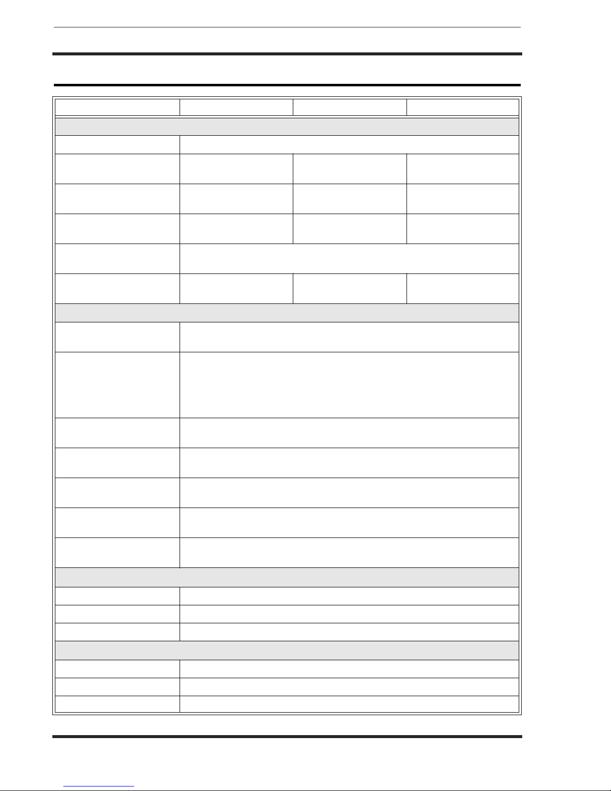
GENERAL PRINTER SPECIFICATIONS
SPECIFICATION M-84PRO-2 M-84PRO-3 M-84PRO-6
PRINT
Method Direct or Thermal Transfer
Speed (User Selectable) 2 to 10 ips
50 to 250 mm/s
2 to 8 ips
50 to 200 mm/s
2 to 6 ips
50 to 150 mm/s
Print Module (Dot Size) .0049 in.
.125 mm
.0033 in.
.083 mm
0017 in.
.081 mm
Resolution 203 dpi
8 d/mm
305 dpi
12 d/mm
609 dpi
24 d/mm
Maximum Print Width 4.1 in.
104 mm
Maximum Print Length 49.2 in.
1249 mm
32.8 in.
835 mm
14.0 in.
356 mm
MEDIA
Minimum Width .87 in.
22 mm
Minimum Length
Continuous
Tea r- O ff
Cutter
Dispense
0.24 in. (6 mm)
0.63 in. (16 mm)
1.18 in. (30 mm)
1.18 in. (30 mm)
Maximum Width 5.0 in.
125 mm
Type Roll or Fan-Fold Die Cut Labels
Thermally Sensitive
Maximum Caliper 0.008 in.
0.21 mm
Roll OD (max) Face-In 8.6 in.
220 mm
Core ID (min) 3 in
76.2 mm
SENSING
See-Thru Movable
Reflective Eye-Mark Movable
Continuous Form Sensor Not Used
RIBBON
Maximum Width 4.4 in. (111 mm)
Length (max) 1475 ft. (450 m)
Thickness 4.5 micron, Wound Face-In
Operation Manual Section 1: Overview
SATO M-84PRO Page 1-3
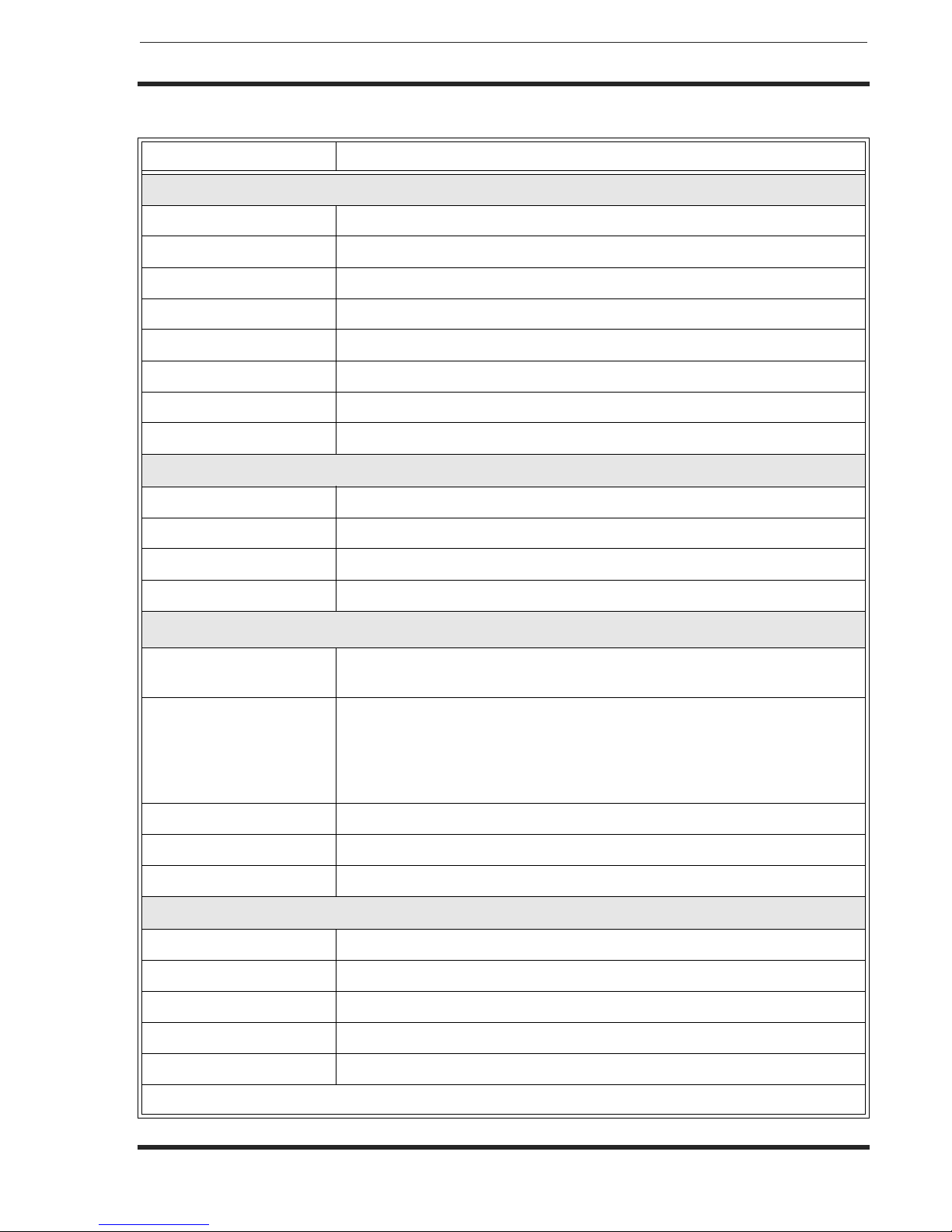
SPECIFICATION M-84PRO All Models
CONTROLS AND INDICATORS
Power Green LED
On-Line Green LED
Label Red LED
Ribbon Red LED
Error Red LED
LCD Panel 2 Line x 16 Character
Label Feed Front Panel
Power On/Off Switch Front Panel
POTENTIOMETER ADJUSTMENTS
Print Darkness Front Panel
Offset Front Panel
Pitch Front Panel
Display Front Panel
INTERFACE CONNECTIONS (1)
Parallel IEEE1284 Standard
Centronics
Serial RS232C (2,400 to 19,200 bps)
RS232C (9,600 to 57,600 bps) Standard
RS422/485 (9,600 to 57,600 bps) Optional
Ready/Busy or X-On/X-Off Flow Control
Bi-directional Status
Universal Serial Bus USB Ver. 1.1 Standard
LAN 10/100BaseT
Wireless LAN 802.11b
PROCESSING
CPU 32 Bit RISC
Flash ROM 2 MB
SDRAM 16 MB
Receive Buffer 2.95 MB
Memory Expansion See Options and Accessories
(1) Only one interface module can be installed in a printer at a time.

Section 1: Overview Operation Manual
Page 1-4 SATO M-84PRO
CHARACTER FONTS
SPECIFICATION M-84PRO-2 M-84PRO-3 M-84PRO-6
MATRIX FONTS
U Font 5 dots W x 9 dots H
S Font 8 dots W x 15 dots H
M Font 13 dots W x 20 dots H
XU Font 5 dots H x 9 dots H (Helvetica)
XS Font 17 dots H x 17 dots W (Univers Condensed Bold)
XM Font 24 dots H x 24 dots W (Univers Condensed Bold)
OA Font (OCR-A) 15 dots W x 22 dots H 22 dots W x 33 dots H 44 dots W x 66 dots H
OB Font (OCR-B) 30 Dots W x 36 dots H 30 Dots W x 36 dots H 60 dots W x 72 dots H
AUTO SMOOTHING FONTS
WB 18 dots W x 30 dots H
WL 28 dots H x 52 dots H
XB 48 dots H x 48 dots W (Univers Condensed Bold)
XL 48 dots W x 48 dots H (Sans Serif)
VECTOR FONT
Proportional or Fixed Spacing
Font Size 50 x 50 dots to 999 x 999 dots
Helvetica, 10 Font Variations
AGFA® RASTER FONTS
Font A CG Times ®, 8 pt to 72 pt
Font B CG Triumvirate®, 8 pt to 72 pt
DOWNLOADABLE FONTS
Bit Mapped TrueType® Fonts with Utility Program
CHARACTER CONTROL
Expansion to 12X in either X or Y coordinates
Character Pitch control
Line Space control
Journal Print facility
0°, 90°, 180° and 270° Rotation

Operation Manual Section 1: Overview
SATO M-84PRO Page 1-5
BARCODES
BARCODE M-84PRO All Models
SYMBOLOGIES
Linear Barcodes Bookland (UPC/EAN Supplemental)
EAN-8/EAN-13
CODABAR
CODE 39
CODE 93
CODE 128
Interleaved 2 of 5 (I 2/5)
Industrial 2 of 5
Matrix 2 of 5
MSI
POSTNET
UCC/EAN-128
UPC-A/UPC-E
Two Dimensional Data Matrix
Maxicode
PDF417
Micro PDF
Truncated PDF
QR Code
Ratios 1:2, 1:3, 2:5, User Programmable
Bar Height 4 to 999 dots, User Programmable
Rotation 0°, 90°, 180° and 270° Rotation
OTHER FEATURES
Sequential Numbering Sequential numbering of both numerics and barcodes
Custom Characters RAM storage for custom designed characters
Graphics Dot addressable, SATO Hex/Binary, BMP or PCX formats
Forms Overlay Overlay of predesigned forms in image buffer

Section 1: Overview Operation Manual
Page 1-6 SATO M-84PRO
PHYSICAL
SPECIFICATION M-84PRO All Models
PHYSICAL
Wide 10.4 in. (265 mm)
Deep 17.1 in. (435 mm)
High 13.4 in.(341 mm)
Weight 39.7 lb. (18.0 Kg)
POWER
Input Voltage 115/220 VAC +/-10%, 50/60 Hz +/-1%
Power Consumption 130W Operating, 24W Idle
ENVIRONMENTAL
Operating Temperature 41° to 104°F (5° to 40°C)
Storage Temperature 23° to 140°F (-5° to 60°C)
Storage Humidity 30 to 90% RH Non-Condensing
Operating Humidity 30 to 80% RH Non-Condensing
Electrostatic Discharge 8kV
REGULATORY APPROVALS
Safety VCCI (Class B), UL, CUL, CE, FCC Class B
RFI/EMI FCC Class B
Operation Manual Section 1: Overview
SATO M-84PRO Page 1-7
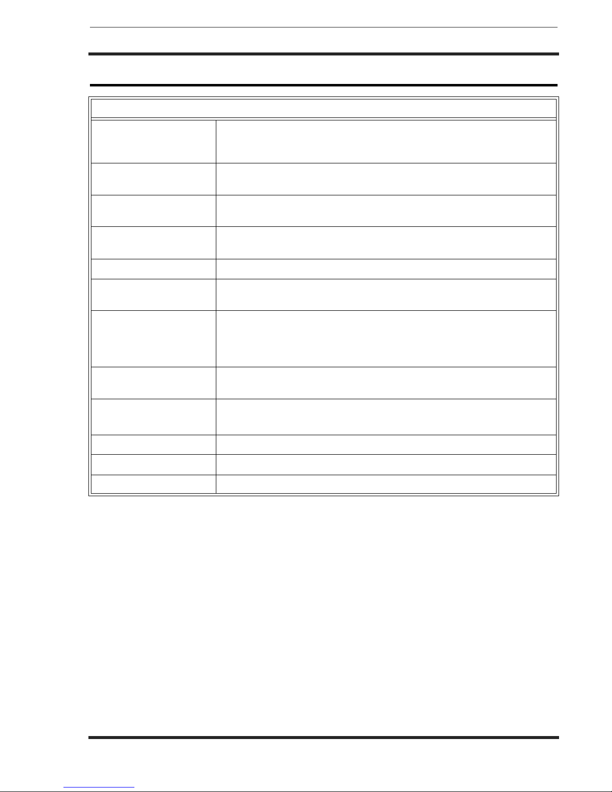
OPTIONAL ACCESSORIES
All specifications subject to change without notice.
ACCESSORIES AND OPTIONS
PCMCIA MEMORY
EXPANSION
One slot for PCMCIA Memory Card (up to 4 MB SRAM or 16 MB Flash
ROM). Can be used for graphic file storage, print buffer expansion, format
storage and downloaded fonts.
FLASH ROM
EXPANSION
Internal 4MB Flash ROM PCB.
REAL TIME CLOCK An internal Date/Time clock that can be used to date/time stamp labels at
the time of printing.
LABEL DISPENSER Internally mounted attachment allowing labels to be peeled from backing
for immediate (on demand) applications. Backing not rewound.
LABEL REWINDER External Option that rewinds labels onto a roll after they are printed.
LABEL CUTTER An attachment allowing labels to be cut at specified intervals. Controlled
through programming.
COAX/TWINAX
INTERFACE
Coan/Twinax Plug-In Interface module. Coax interface emmulates an IBM
3287-2 printer with a stndard Type A BNC connector. Twinax interface
emulates IBM 5224, 5225, 5226 or 4214 printers with auto-terminate/
cable through capabilities.
PARALLEL INTERFACE IEEE1284 Bi-Directional Plug-In Interface Module
Centronics Plug-In Interface Module
SERIAL INTERFACE High Speed RS232 Plug-In Interface Module
Slow RS232 Plug-In Interface Module
USB INTERFACE Universal Serial Bus Plug-In Interface Module
LAN INTERFACE 10/100 BaseT Plug-In Interface Module
WIRELESS LAN 802.11b Plug-In Interface Module

Operation Manual Section 2. Installation
SATO M-84PRO Page 2-1
SECTION 2.
INSTALLATION
INTRODUCTION
This section of the manual has been written to help you install the SATO M-84PRO printers and
to get started as quickly as possible. It is recommend to read each chapter in this manual before
the installation or the use of the printers.
The following information is provided in this section:
• Setting Up the Printer
• Loading Labels or Tags
• Loading the Ribbon
• Operator Panel
SETTING UP THE PRINTER
Consider the following when setting up the printer:
• Locate a solid flat surface with adequate room to set the printer. Make sure there is enough
room at the top and right-hand (facing the printer) side to provide clearance for the label
access door to swing open.
• The location should be near the host computer or terminal. The maximum distance for RS232
cables is 35 feet and six feet for IEEE1284 Parallel cables. Cables can be purchased locally,
and their configuration will depend upon the host system being used. A IEEE1284 compliant
cable must be used to realize the full throughput potential of the printers.
• For information on interfacing the printer to a host system, see Section 5: Interface
Specifications.

Section 2. Installation Operation Manual
Page 2-2 SATO M-84PRO
DIP Switch
Cover
LCD
Display
Power Switch
Ribbon Rewind
Spindle
Ribbon Supply
Spindle
Side Access
Door
Top Access
Door
Label Roll Retainer
Label Hold Down
Label Supply Spindle
Label Guide
Print Head
Head Latch
Platen

Operation Manual Section 2. Installation
SATO M-84PRO Page 2-3
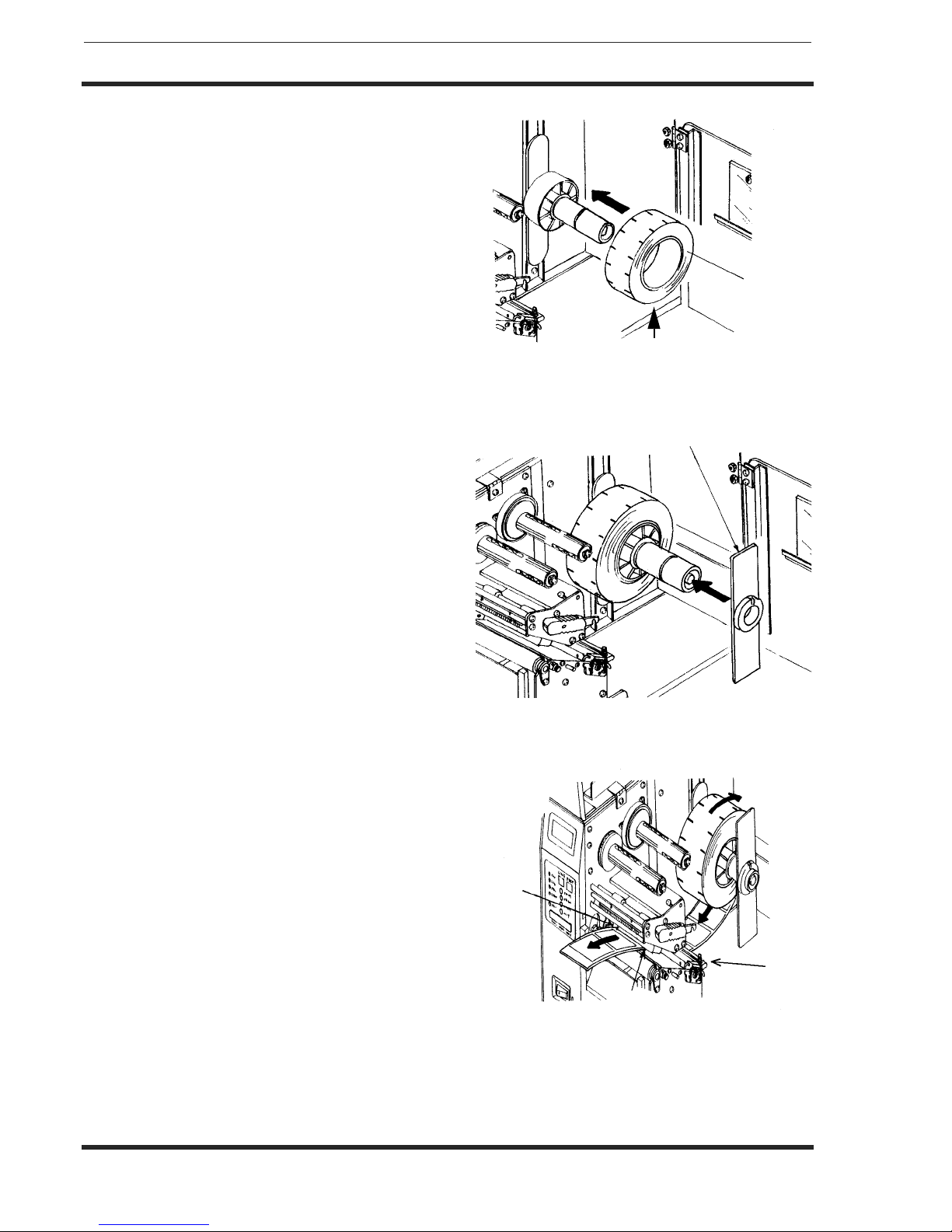
LOADING LABELS AND TAGS
1. Open the Top Access Door by swinging it up
and to the left. Open the Side Access Door by
swinging it to the rear of the printer.
2. Open the Print Head Assembly by pushing the
Head Latch toward the rear of the printer. The
Print Head Assembly is spring-loaded and will
automatically open as soon as the Head Latch
is disengaged.
3. Loosen the Label Edge Guide and push it to
the outside of the printer to give the maximum
label width.
4. Remove the Label Roll Retainer
Top Access Door
Side Access
Door
Label Roll Retainer
Head Latch
Print Head
Sensor Assembly
Label Hold Down
Label Edge Guide
Label
Guide
Section 2. Installation Operation Manual
Page 2-4 SATO M-84PRO
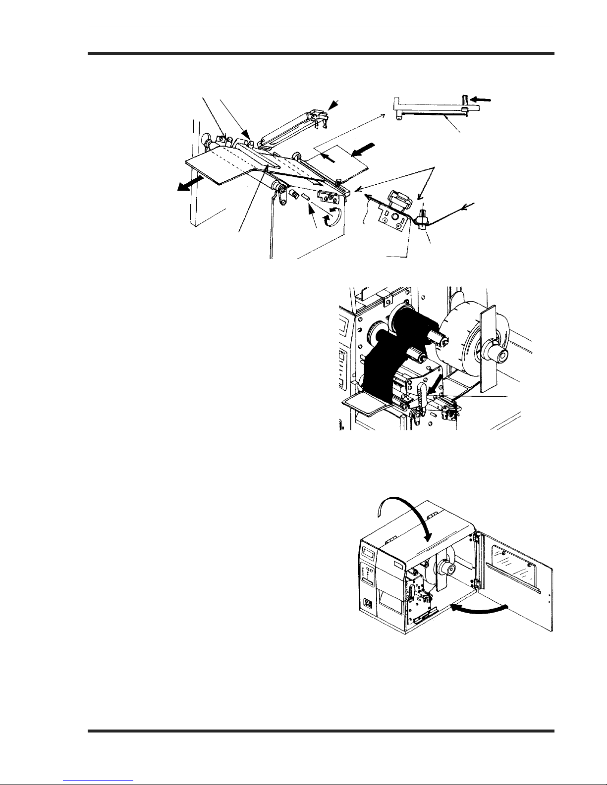
5. If using roll labels (or tags), load the roll onto
the Label Supply Spindle so that the printing
side of the labels faces upwards as it unwinds
from the roll. The labels should be wound
face-in. Push the roll all the way to the inside
of the printer and push the Label Roll Retainer
snugly against the outside of the label roll.
6. If using fanfold labels (or tags) set them on a
flat surface behind the printer. Pass the labels
(printing side up) through the slot in the rear of
the printer.
7. Make sure the labels are routed under the
Label Guide and through the Sensor
Assembly.
8. Open the Label Hold-Down by squeezing the
green tab and the release tab together. The
Label Hold Down is spring loaded and will
open automatically when the latch is
disengaged. Feed the labels under the Label
Guide, under the Label Hold Down, through
the Sensor Assembly and out the front of the
printer.
9. Inspect the label routing and verify that the
path matches that illustrated in the Label
Loading diagram. Set the Adjustable Label
Guide to keep the labels against the inside of
the printer.
10. Close the Label Hold-Down by pushing
downward on the green tab until it latches closed.
NOTE: If the Label Dispenser option has been
purchased, see Appendix A, for proper
label routing instructions.
Label Roll
Label Roll Retainer
Print
Head
Label
Guid
e
Operation Manual Section 2. Installation
SATO M-84PRO Page 2-5
11. Adjust the outside Label Edge Guide until it
touches the outside edge of the label and
tighten the thumb screw. Make sure the
labels are also touching the inside edge
guides.
CAUTION: Using media narrower than the
maximum print width may cause excess
head wear due to the label edge. See page
2-9 for precautions.
12. If the ribbon is already loaded, close the Print
Head by rotating the black Head Latch
toward the front of the printer until it latches
closed.
13. If the ribbon is not loaded, see the following description for loading instructions.
14. Close both the Access Doors.
Route Labels
Under Guide
Label Hold Down
Inside Label Edge Guides
Sensor
Positioning
Sensor
Assembly
Head
Latch
Section 2. Installation Operation Manual
Page 2-6 SATO M-84PRO
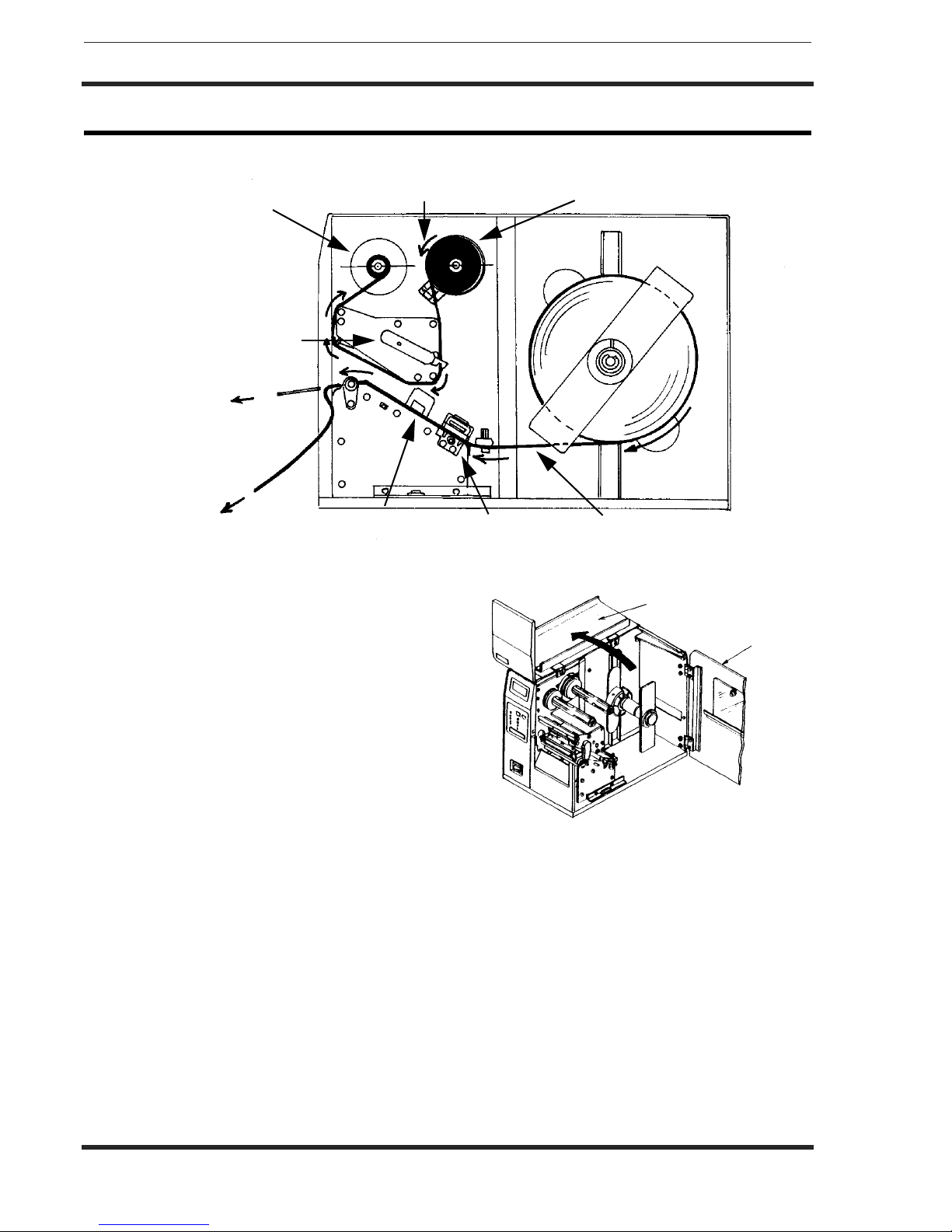
LOADING THE RIBBON
1. Open the Top Access Door by
swinging it up and to the left and the
Side Access Door by swinging it
toward the rear of the printer.
2. Open the Print Head by rotating the
Head Latch toward the rear of the
printer. The Print Head is spring-loaded
and will automatically open as soon as
the Head Latch is disengaged.
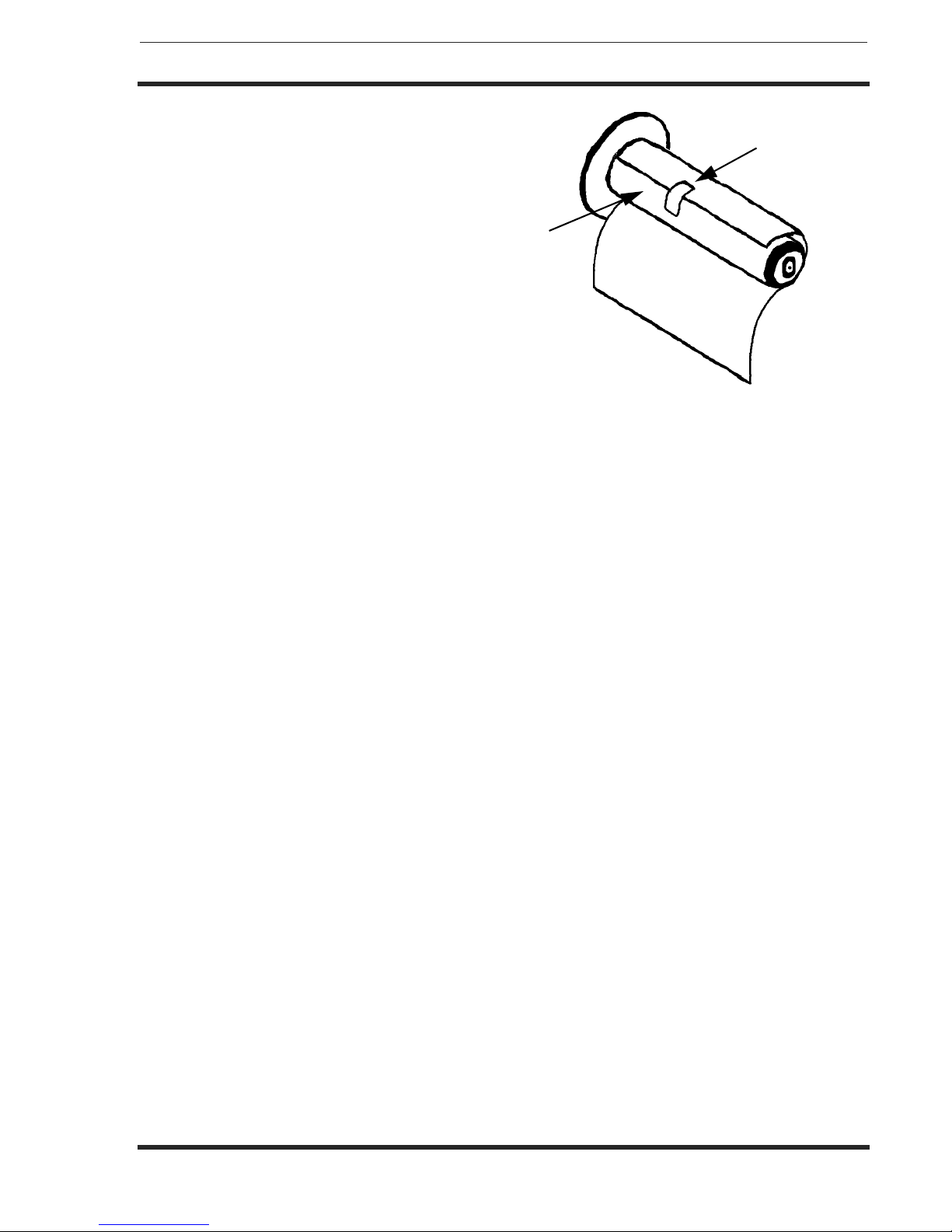
3. Locate the extra ribbon core supplied
with the printer. Place the core on the
Ribbon Rewind Spindle, pushing it all
the way to the inside of the spindle.
Note that the new empty core of each
subsequent roll becomes the next rewind core.
4. Load the ribbon onto the Ribbon Supply Spindle, also pushing it all the way to the inside of
the spindle. The dull side of the ribbon should be facing down as it travels through the Print
Head Assembly.
5. Feed the leader portion of the ribbon through the Print Head Assembly and up to the Ribbon
Rewind Spindle following the routing shown in the diagram.
6. Load the ribbon behind and over the top of the Ribbon Rewind Spindle and tape it to the
Extra Ribbon Core. Make sure it matches the ribbon path shown in the diagram.
7. Manually turn the Rewind Spindle to wrap the ribbon onto the core one to two turns to
secure it.
Ribbon Roll
Ribbon Path
Ribbon Rewind
Spindle
Head Latch
Dispensed
Label
Label Backing Sensor
Assembly Label Hold
Down
Label Path
Top Access Door
Side Access Door
Operation Manual Section 2. Installation
SATO M-84PRO Page 2-7
8. If the labels or tags are already loaded,
close the Print Head Assembly by
pushing downward on the green tab
until it latches closed.
9. Run a test print to ensure that the
labels and ribbons were loaded
correctly.
CAUTION: If your labels are less than the full width of the print head, the outside edge will
eventually wear out a small portion of the print head, resulting in an area that will not
print. Special care must be taken if you plan to use multiple widths of labels, since the
damaged portion of the print head caused from edge wear on a more narrow label may
affect the printing on a wider label. We suggest you plan your print formats carefully to
avoid using the area of possible damage on the print head when using a wider label. The
small area of damage will have no effect on printing with the undamaged part of the print
head. Damage from a label edge is physical damage and is unavoidable. It is not covered
by warranty. It is possible to delay such damage by always ensuring that the ribbon used
is wider than the label stock. This will help to protect the print head from label edge
damage.
Tap e
Ribbon
Core

Section 2. Installation Operation Manual
Page 2-8 SATO M-84PRO
OPERATOR PANEL
The M-84PRO Operator Panel consists of five LED indicators, two momentary contact switches, three
DIP switches, four adjustment potentiometers and one LCD Display. All of these are accessible from the
front of the printer. They are used to set the printer operating parameters and to indicate the status of the
printer to the operator. After you power on the printer, familiarize yourself with the keys and indicators as it
will help you understand the configuration process.
PRINT Potentiometer to adjust print darkness (fine tuning)
OFFSET Potentiometer to adjust amount of back/forward feed for dispenser/cutter/
tear-off position (+/- 3.75 mm)
PITCH Potentiometer to adjust home position of the label (+/- 3.75 mm). Affects stop
position of label feed, print position and dispense position.
DISPLAY Potentiometer to adjust the contrast of the LCD display.
POWER LED, illuminated when the power is on.
LABEL LED, illuminated when the label supply is not detected.
RIBBON LED, illuminated when the ribbon motion sensor does not detect any ribbon
motion (ribbout out condition).
ERROR LED, illuminated when there is a system fault such as an open print head.
Other manuals for M-84Pro Series
6
This manual suits for next models
3
Table of contents
Other SATO Printer manuals


SATO
SATO CX200 User manual

SATO
SATO S8412 Standard User manual

SATO
SATO MB200 User manual

SATO
SATO M-8400 User manual

SATO
SATO MR-4206 User manual

SATO
SATO CLe RFID Smart User manual

SATO
SATO M-8490Se Series User manual

SATO
SATO CG4 Series User manual

SATO
SATO CL408e User manual

SATO
SATO TG3 Series User manual


