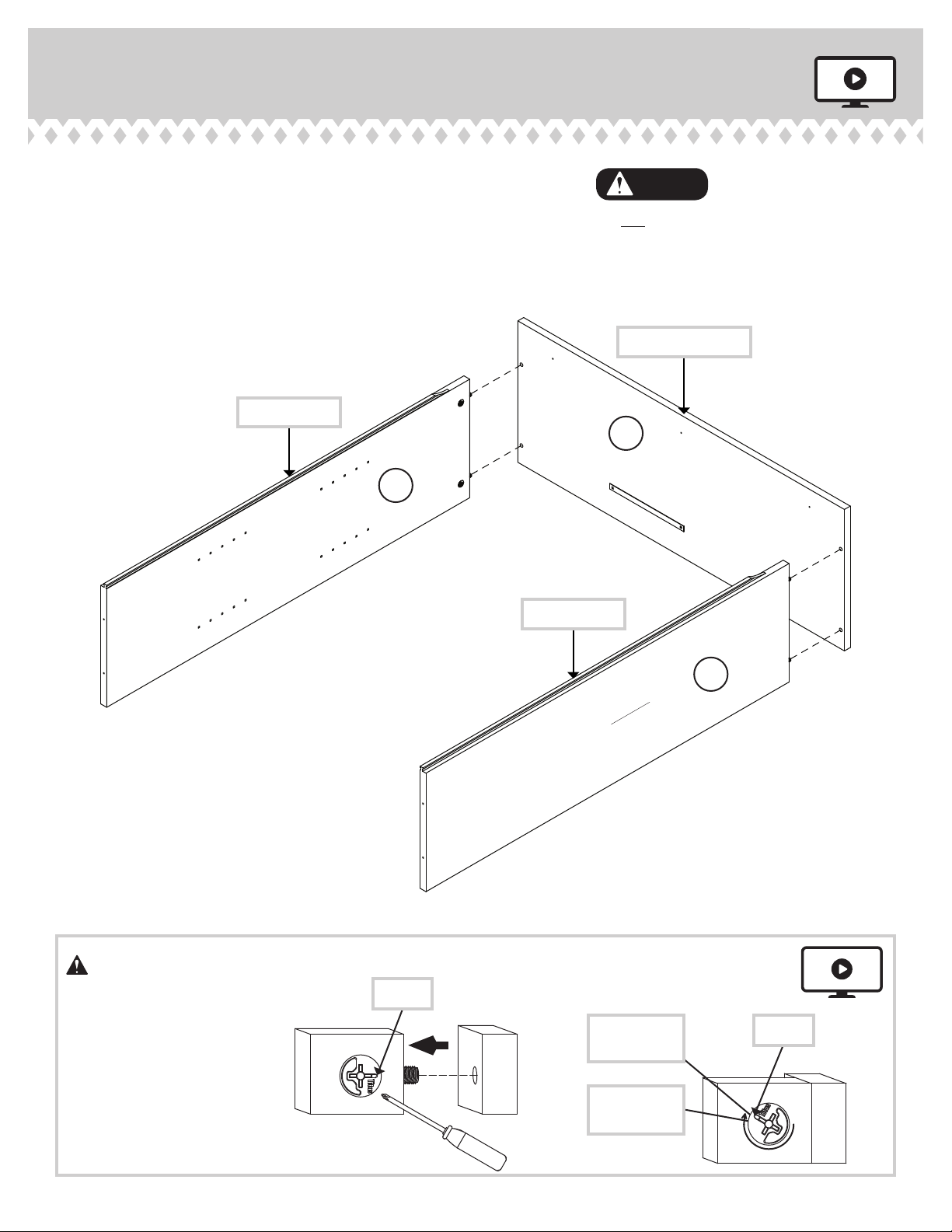
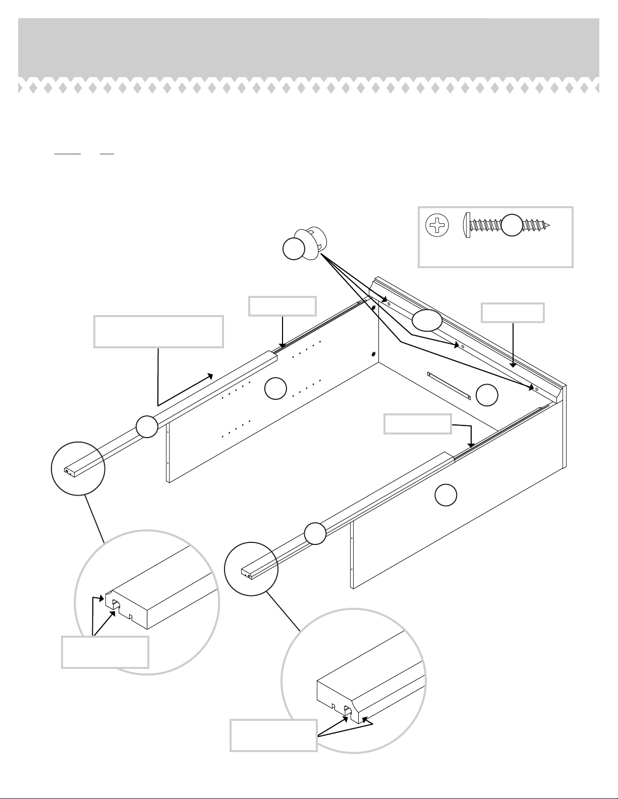
Sauder 420174 User manual
Other Sauder Indoor Furnishing manuals

Sauder
Sauder Orchard Hills 401292 User manual

Sauder
Sauder Orchard Hills 401346 User manual

Sauder
Sauder Parklane 423107 User manual

Sauder
Sauder Night Stand 423434 User manual

Sauder
Sauder Shoal Creek 422191 User manual

Sauder
Sauder Harvest Mill 404962 User manual

Sauder
Sauder Carson Forge 414444 User manual

Sauder
Sauder Credenza 425765 User manual

Sauder
Sauder Coral Cape 423808 User manual

Sauder
Sauder Englewood 426908 User manual

Sauder
Sauder Manhattan Gate 429251 User manual

Sauder
Sauder Shoal Creek Series User manual

Sauder
Sauder 417886 User manual

Sauder
Sauder OfficeWorks AFFIRM 426285 User manual

Sauder
Sauder Harvest Mill 404958 User manual

Sauder
Sauder Briarbrook 430070 User manual

Sauder
Sauder Carson Forge 412920 User manual

Sauder
Sauder 420566 User manual

Sauder
Sauder Palladia Credenza 415025 User manual

Sauder
Sauder OfficeWorks AFFIRM 427442 User manual


Popular Indoor Furnishing manuals by other brands

Regency
Regency LWMS3015 Assembly instructions

Furniture of America
Furniture of America CM7751C Assembly instructions

Safavieh Furniture
Safavieh Furniture Estella CNS5731 manual

PLACES OF STYLE
PLACES OF STYLE Ovalfuss Assembly instruction

Trasman
Trasman 1138 Bo1 Assembly manual

Costway
Costway JV10856 manual