manuals.online logo
Brands
  1. Home
  2. •
  3. Brands
  4. •
  5. Sauder
  6. •
  7. Indoor Furnishing
  8. •
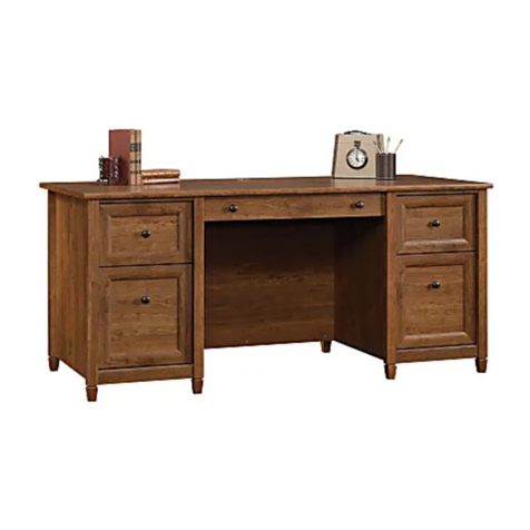
  9. Sauder Barrister Lane 414836 User manual

Sauder Barrister Lane 414836 User manual

PLEASE CONTACT US
BEFORE RETURNING
YOUR UNIT TO THE STORE
1-800-523-3987
www.sauder.com
Made in the USA
Archbold, OH
NOTE: THIS INSTRUCTION BOOKLET CONTAINS
IMPORTANT SAFETY INFORMATION.
PLEASE READ AND KEEP FOR FUTURE REFERENCE.
English.................... Page 1-30
Français...............Pages 31-33
Espanol.............Páginas 34-36
Lot #: 353042 05 / 09 / 13
Date Purchased: ____________________
414836
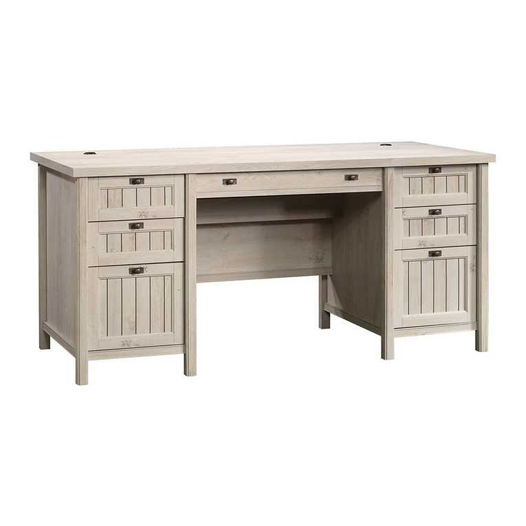
Desk
Barrister Lane Collection
ADULT ASSEMBLY REQUIRED
ASSEMBLY TOOLS REQUIRED
Hammer
No. 2 Phillips Screwdriver
Tip Shown Actual Size
A INNER RIGHT END 1
B OUTER RIGHT END 1
C LEFT END 1
D UPRIGHT 1
E TOP 1
F BOTTOM 1
G MODESTY PANEL 1
H UPPER SHELF 1
I LOWER SHELF 1
J DIVIDER 1
K BACK 1
L SIDE SKIRT 4
M PENCIL DRAWER FRONT 1
N TOP FRONT MOLDING 1
O LEFT TOP MOLDING 1
P RIGHT TOP MOLDING 1
Q SHELF MOLDING 1
R LEFT MOLDING 2
S FILE DRAWER FRONT 1
T RIGHT FRONT MOLDING 1
U BASE 1
V RIGHT REAR MOLDING 1
W LOWER SHELF MOLDING 1
X EXTENSION BLOCK 1
Y PLINTH 1
D28 FILE RIGHT DRAWER SIDE 1
D29 FILE LEFT DRAWER SIDE 1
D78 FILE DRAWER BACK 1
D95 PENCIL RIGHT DRAWER SIDE 1
D96 PENCIL LEFT DRAWER SIDE 1
D125 PENCIL DRAWER BOX FRONT 1
D126 PENCIL DRAWER BACK 1
D707 FILE DRAWER BOTTOM 1
D731 PENCIL DRAWER BOTTOM 1
TABLE OF CONTENTS
Part Identification...................2-3
Hardware Identification .............4
Assembly Steps....................5-30
Français..............................31-33
Espanol...............................34-36
Safety .................................37-38
Warranty...................................39
PART IDENTIFICATION: While not all parts are labeled, some of the parts will have a label or an inked
letter on the edge to help distinguish similar parts from each other. Use this PART IDENTIFICATION to help
identify similar parts.
Page 2 www.sauder.com/services 414836
Short Screwdriver
PART IDENTIFICATION:
Page 3
www.sauder.com/services414836
A
B
C
D
E
F
G
H
I
J
K
LM
N
O
P
Q
R
S
T
U
V
W
X
Y
L
L
R
L
D707
D731
D125
D126
D95
D96
D78 D28
D29
HARDWARE IDENTIFICATION
Screws are shown actual size. You may receive extra hardware with your unit.
40CA CABINET
RIGHT - 1
Page 4 www.sauder.com/services 414836
FILE GLIDE - 2
15B
FILE ROD - 2
8B
AA EXTENSION
SLIDE - 2
ZEXTENSION
RAIL - 2
(EXTENSION SET SHOWN SEPARATED)
40CB CABINET
LEFT - 1 40CC DRAWER
RIGHT - 1
40CD DRAWER
LEFT - 1 SLIDE CAM - 2
10A
GOLD 5/16" FLAT HEAD SCREW - 18
3S
TWIST-LOCK®FASTENER - 18
10F
NAIL - 22
1N
BLACK 1-7/8" FLAT HEAD SCREW - 8
2S
METAL PIN - 4
1R
METAL
BRACKET - 5
4G
BLACK 9/16" LARGE HEAD SCREW - 10
1S
SILVER 7/8" MACHINE SCREW - 6
42S
GRAY 1-3/8" MACHINE SCREW - 2
39S
BLACK 7/8" LARGE HEAD SCREW - 2
17S
GROMMET - 1
7P GROMMET CAP- 1
8P
SILVER 1-1/8" FLAT HEAD SCREW - 8
10S
SILVER 1/2" MACHINE SCREW - 4
38S
MOLDING
CONNECTOR - 2
19F SPRING
CLIP - 1
38G
SILVER 7/8" FLAT HEAD SCREW - 2
96S
BLACK 1" PAN HEAD SCREW - 8
60S
PULL - 1
70K KNOB - 6
71K CARD
HOLDER - 2
35M
BLACK 1-9/16" FLAT HEAD SCREW - 6
30S
Look for this icon. It means a video
assembly tip is available at:
www.sauder.com/services/tips
1
1
S
t
e
p
Assemble your unit on a carpeted floor or on the empty carton to avoid scratching your unit or the floor.
To begin assembly, push a SAUDER TWIST-LOCK® FASTENER (10F) into the large holes in the ENDS (A and B). Repeat this step
for the LEFT END (C), UPRIGHT (D), MODESTY PANEL (G), and SHELVES (H and I).
Page 5
www.sauder.com/services414836
Do not tighten the TWIST-LOCK® FASTENERS in this step.
(18 used)
10F
A
B
Page 6 www.sauder.com/services 414836
2
2
S
t
e
p
Tap two MOLDING CONNECTORS (19F) into the notches in the MOLDINGS (N, O, and P).
Flat end
Flat end
Use your hammer to tap the MOLDING CONNECTOR (19F) into the notches in the MOLDINGS.
19F
N
19F
P
O
Carefully turn the MOLDINGS over.
Fasten the MOLDINGS (N, O, and P) to the TOP (E). Use eight SILVER 1-1/8" FLAT HEAD SCREWS (10S).
Page 7
www.sauder.com/services414836
3
3
S
t
e
p
SILVER 1-1/8" FLAT HEAD SCREW
(8 used in this step)
10S
N
P
O
E
Surface with holes
Long curved edge
Finished surface
Finished surface
Finished surface
Fasten the SKIRTS (L) to the ENDS (A and B). Use four BLACK 1" PAN HEAD SCREWS (60S).
Page 8 www.sauder.com/services 414836
4
4
S
t
e
p
A
B
Surface with
TWIST-LOCK
®
FASTENERS
Surface without
TWIST-LOCK
®
FASTENERS
L
L
BLACK 1" PAN HEAD SCREW
(4 used in this step)
60S
Short unfinished edge
These edges
should be even.
Fasten the EXTENSION BLOCK (X) to the UPRIGHT (D). Use two SILVER 7/8" FLAT HEAD SCREWS (96S) through the large
holes in the EXTENSION BLOCK.
Fasten a CABINET RIGHT (40CA) to the INNER RIGHT END (A) and a CABINET LEFT (40CB) to the EXTENSION BLOCK (X ).
Use four GOLD 5/16" FLAT HEAD SCREWS (3S) through holes #1 and #3.
Page 9
www.sauder.com/services414836
5
5
S
t
e
p
Surface with
TWIST-LOCK
®
FASTENERS
Surface without
TWIST-LOCK
®
FASTENERS
A
X
D
GOLD 5/16” FLAT HEAD SCREW
(4 used for the RAILS)
3S
1
2
34
43
2
1
Roller end
Roller end
SILVER 7/8" FLAT HEAD SCREW
(2 used for the EXTENSION BLOCK)
96S
Finished surface
Notched edge
These holes
must be here.
Page 10 www.sauder.com/services 414836
6
6
S
t
e
p
Separate the EXTENSION SLIDES (AA) from the EXTENSION RAILS (Z) as shown in the upper diagram. Be prepared, the parts
are greasy.
Fasten an EXTENSION RAIL (Z) to the LEFT END (C) and UPRIGHT (D). Use four GOLD 5/16" FLAT HEAD SCREWS (3S).
NOTE: For each EXTENSION RAIL, turn a SCREW into the hole shown in the enlarged diagram. Then, slide the inner
cartridge of the EXTENSION RAIL in to find the other hole that lines up with the hole in the END and UPRIGHT. Turn a SCREW
into this hole.
Slide the LEFT MOLDINGS (R) onto the notched edges of the LEFT END (C) and UPRIGHT (D).
*U.S. Patent No. 5,499,886
Push the black lever in and pull the SLIDE from the RAIL.
Open end
Open end
Z
AA
Surface with
TWIST-LOCK
®
FASTENERS
R
Surface with
TWIST-LOCK
®
FASTENERS
D
C
R
Z
Z
Notched edge
Notched edge
GOLD 5/16” FLAT HEAD SCREW
(4 used for the RAILS)
3S
The MOLDING (R) should
be even with this edge.
The MOLDING (R)
should be even with
this edge.
Page 11
www.sauder.com/services414836
7
7
S
t
e
p
Fasten the OUTER RIGHT END (B) to the RIGHT TOP MOLDING (P) on the TOP (E). Tighten two TWIST-LOCK®FASTENERS.
How to use the SAUDER TWIST-LOCK®FASTENER
1. Insert the dowel end of the FASTENER into the
hole of the adjoining part.
NOTE: The dowel end of the FASTENER must remain
fully inserted in the hole of the adjoining part while
locking the FASTENER.
2. Tighten the FASTENER with a Phillips screwdriver
as tight as possible.
Dowel end
B
P
E
Surface with
TWIST-LOCK®
FASTENERS
Long curved edge
Use outer holes.
Fasten the MODESTY PANEL (G) to the INNER RIGHT END (A) as shown in the upper diagram. Use two BLACK 1-7/8" FLAT
HEAD SCREWS (2S).
Then, fasten the INNER RIGHT END (A) to the RIGHT TOP MOLDING (P) and the MODESTY PANEL (G) to the TOP (E).
Tighten four TWIST-LOCK®FASTENERS.
Page 12 www.sauder.com/services 414836
8
8
S
t
e
p
P
E
G
A
G
A
Surface with
TWIST-LOCK
®
FASTENERS
Surface with
TWIST-LOCK®
FASTENERS
BLACK 1-7/8" FLAT HEAD SCREW
(2 used in this step)
2S
Edge with
TWIST-LOCK®
FASTENERS
Roller end
Surface with
TWIST-LOCK®
FASTENERS
Surface with
TWIST-LOCK®
FASTENERS
Roller end
Long curved edge
Page 13
www.sauder.com/services414836
9
9
S
t
e
p
A
B
Slide the MOLDINGS (T and V) onto the notched edges of the ENDS (A and B).
NOTE: The RIGHT FRONT MOLDING (T) is shorter than the RIGHT REAR MOLDING (V). Do not confuse these MOLDINGS.
*U.S. Patent No. 5,499,886
T
V
The MOLDINGS should
rest against the RIGHT
FRONT MOLDING.
Slide the PLINTH (Y) onto the notched edge of the OUTER RIGHT END (B). Then, insert the SPRING CLIP (38G) into the groove
in the PLINTH to lock it into position.
Fasten the UPRIGHT (D) to the TOP (E). Tighten two TWIST-LOCK®FASTENERS.
Fasten the UPRIGHT (D) to the MODESTY PANEL (G). Use two BLACK 1-7/8" FLAT HEAD SCREWS (2S).
Page 14 www.sauder.com/services 414836
10
10
S
t
e
p
BLACK 1-7/8" FLAT HEAD SCREW
(2 used in this step)
2S
D
E
G
Surface with
TWIST-LOCK®
FASTENERS
R
Y
38G
B
Page 15
www.sauder.com/services414836
11
11
S
t
e
p
Fasten the UPPER SHELF (H) to the UPRIGHT (D). Tighten two TWIST-LOCK®FASTENERS.
NOTE: Once the UPPER SHELF (H) is fastened to your unit, do not apply any pressure to the UPPER SHELF. It may break.
Slide the SHELF MOLDING (Q) onto the notched edge of the UPPER SHELF (H).
*U.S. Patent No. 5,499,886
D
H
Q
Surface with
TWIST-LOCK®
FASTENERS
Notched edge
Do not apply any
pressure to the
UPPER SHELF (H).
Page 16 www.sauder.com/services 414836
12
12
S
t
e
p
H
Insert four METAL PINS (1R) into the DIVIDER (J).
Insert the METAL PINS (1R) in one end of the DIVIDER (J) into the holes in the UPPER SHELF (H).
NOTE: Do not apply any pressure to the UPPER SHELF. It may break.
1R
Finished edge
JDo not apply any
pressure to the
UPPER SHELF (H).
Page 17
www.sauder.com/services414836
13
13
S
t
e
p
J
Fasten the LOWER SHELF (I) to the UPRIGHT (D). Tighten two TWIST-LOCK®FASTENERS.
NOTE: Be sure the METAL PINS in the DIVIDER (J) insert into the holes in the LOWER SHELF (I).
D
I
Surface with
TWIST-LOCK®
FASTENERS
These holes
must be here.
Do not apply any
pressure to the
SHELVES (H and I).
Fasten two CARD HOLDERS (35M) to the LOWER SHELF MOLDING (W). Use four SILVER 1/2" MACHINE SCREWS (38S).
Fasten two METAL BRACKETS (4G) to the LOWER SHELF (I). Use two BLACK 9/16" LARGE HEAD SCREWS (1S).
NOTE: Be sure the BRACKETS are even with the edge of the LOWER SHELF.
Fasten the LOWER SHELF MOLDING (W) to the LOWER SHELF (I). Use two BLACK 9/16" LARGE HEAD SCREWS (1S)
through the METAL BRACKETS and into the holes in the LOWER SHELF MOLDING.
Page 18 www.sauder.com/services 414836
14
14
S
t
e
p
I
BLACK 9/16" LARGE HEAD SCREW
(4 used for the METAL BRACKETS)
1S
4G
SILVER 1/2" MACHINE SCREW
(4 used for the CARD HOLDERS)
38S
W
35M
W
Open end
This hole must
be here.
Do not apply any
pressure to the
SHELVES (H and I).
These surfaces
should be even.
NOTE: You may need to use a SHORT SCREWDRIVER in this step.
Fasten the LEFT END (C) to the SHELVES (H and I) and LEFT TOP MOLDING (O). Tighten six TWIST-LOCK®FASTENERS.
Page 19
www.sauder.com/services414836
15
15
S
t
e
p
I
H
C
O
Surface without
TWIST-LOCK®
FASTENERS
R
Fasten the BOTTOM (F) to the LEFT END (C) and UPRIGHT (D). Use four BLACK 1-7/8" FLAT HEAD SCREWS (2S).
NOTE: To fasten the BOTTOM, be sure to use the bottom set of holes in the LEFT END and UPRIGHT.
Fasten the SIDE SKIRTS (L) to the LEFT END (C) and UPRIGHT (D). Use four BLACK 1" PAN HEAD SCREWS (60S).
Page 20 www.sauder.com/services 414836
16
16
S
t
e
p
L
L
BLACK 1" PAN HEAD SCREW
(4 used for the SIDE SKIRTS)
60S
F
C
D
If the BOTTOM (F) has an unfinished
surface, it should be positioned here.
Short
unfinished
edge
This hole must
be here.
BLACK 1-7/8" FLAT HEAD SCREW
(4 used in this step)
2S Short
unfinished
edge

Other Sauder Indoor Furnishing manuals
Sauder Night Stand 423434 User manual

Sauder

Sauder Night Stand 423434 User manual

Sauder Cottage Road 416039 User manual

Sauder

Sauder Cottage Road 416039 User manual

Sauder Orchard Hills 418651 User manual

Sauder

Sauder Orchard Hills 418651 User manual

Sauder Cannery Bridge 429554 User manual

Sauder

Sauder Cannery Bridge 429554 User manual

Sauder Coral Cape 423808 User manual

Sauder

Sauder Coral Cape 423808 User manual

Sauder 420406 User manual

Sauder

Sauder 420406 User manual

Sauder 403932 User manual

Sauder

Sauder 403932 User manual

Sauder Office Port 408293 User manual

Sauder

Sauder Office Port 408293 User manual

Sauder Shoal Creek Armoire User manual

Sauder

Sauder Shoal Creek Armoire User manual

Sauder 535782 User manual

Sauder

Sauder 535782 User manual

Sauder Clifford Place 429501 User manual

Sauder

Sauder Clifford Place 429501 User manual

Sauder August Hill 433851 User manual

Sauder

Sauder August Hill 433851 User manual

Sauder Camarin Series User manual

Sauder

Sauder Camarin Series User manual

Sauder Summer Home Pantry 401867 User manual
Sauder

Sauder Summer Home Pantry 401867 User manual

Sauder Briarbrook 430076 User manual

Sauder

Sauder Briarbrook 430076 User manual

Sauder Harbor View 403680 User manual

Sauder

Sauder Harbor View 403680 User manual

Sauder 411836 User manual

Sauder

Sauder 411836 User manual

Sauder Entertainment Credenza User manual

Sauder

Sauder Entertainment Credenza User manual

Sauder 412996 Installation guide

Sauder

Sauder 412996 Installation guide

Sauder 423731 User manual

Sauder

Sauder 423731 User manual

Sauder Shoal Creek 411201 User manual

Sauder

Sauder Shoal Creek 411201 User manual

Sauder 422197 User manual

Sauder

Sauder 422197 User manual

Sauder Center City 425653 User manual

Sauder

Sauder Center City 425653 User manual

Sauder Manhattan Gate 429251 User manual

Sauder

Sauder Manhattan Gate 429251 User manual

Popular Indoor Furnishing manuals by other brands

Ergo Furniture STYLE Assembly instructions

Ergo Furniture

Ergo Furniture STYLE Assembly instructions

LDI SAFCO 1008 Assembly instructions

LDI

LDI SAFCO 1008 Assembly instructions

meubar ARUBA W7 Assembly instruction

meubar

meubar ARUBA W7 Assembly instruction

Mocka Kids House Bookcase Assembly instructions

Mocka

Mocka Kids House Bookcase Assembly instructions

OSP furniture TUX-75R Assembly instructions

OSP furniture

OSP furniture TUX-75R Assembly instructions

Coaster 609461PPI Assembly instructions

Coaster

Coaster 609461PPI Assembly instructions

Furinno 10024 Assembly instruction

Furinno

Furinno 10024 Assembly instruction

IKEA PERFEKT manual

IKEA

IKEA PERFEKT manual

Unfinished Furniture of Wilmington OF-52 Assembly instructions

Unfinished Furniture of Wilmington

Unfinished Furniture of Wilmington OF-52 Assembly instructions

Astonica 50103527 instruction manual

Astonica

Astonica 50103527 instruction manual

Pulaski Furniture B027-024-825 Assembly instructions

Pulaski Furniture

Pulaski Furniture B027-024-825 Assembly instructions

SitOnit Seating TENSOR Assembly instructions

SitOnit Seating

SitOnit Seating TENSOR Assembly instructions

NOVIGAMI OTOTO 1059133 Assembly & user instructions

NOVIGAMI

NOVIGAMI OTOTO 1059133 Assembly & user instructions

Furniture of America CM3372-PT Assembly instructions

Furniture of America

Furniture of America CM3372-PT Assembly instructions

leolux Trias Assembly instructions

leolux

leolux Trias Assembly instructions

iLive DTM301WL Assembly Instructions & User Guide

iLive

iLive DTM301WL Assembly Instructions & User Guide

Stompa Uno Highsleeper Nero Assembly instructions

Stompa

Stompa Uno Highsleeper Nero Assembly instructions

Manhattan Comfort 5GMC Assembly guide

Manhattan Comfort

Manhattan Comfort 5GMC Assembly guide

manuals.online logo
manuals.online logoBrands
  • About & Mission
  • Contact us
  • Privacy Policy
  • Terms and Conditions

Copyright 2025 Manuals.Online. All Rights Reserved.