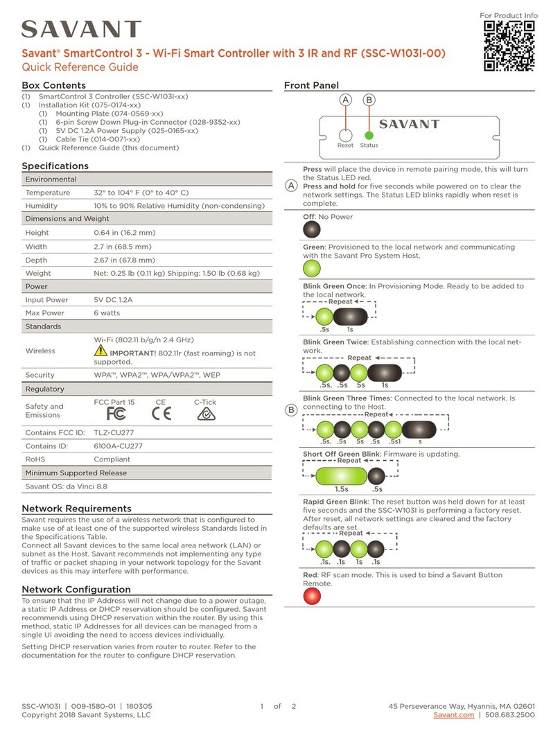
Savant SmartControl 3 User manual
Other Savant Controllers manuals

Savant
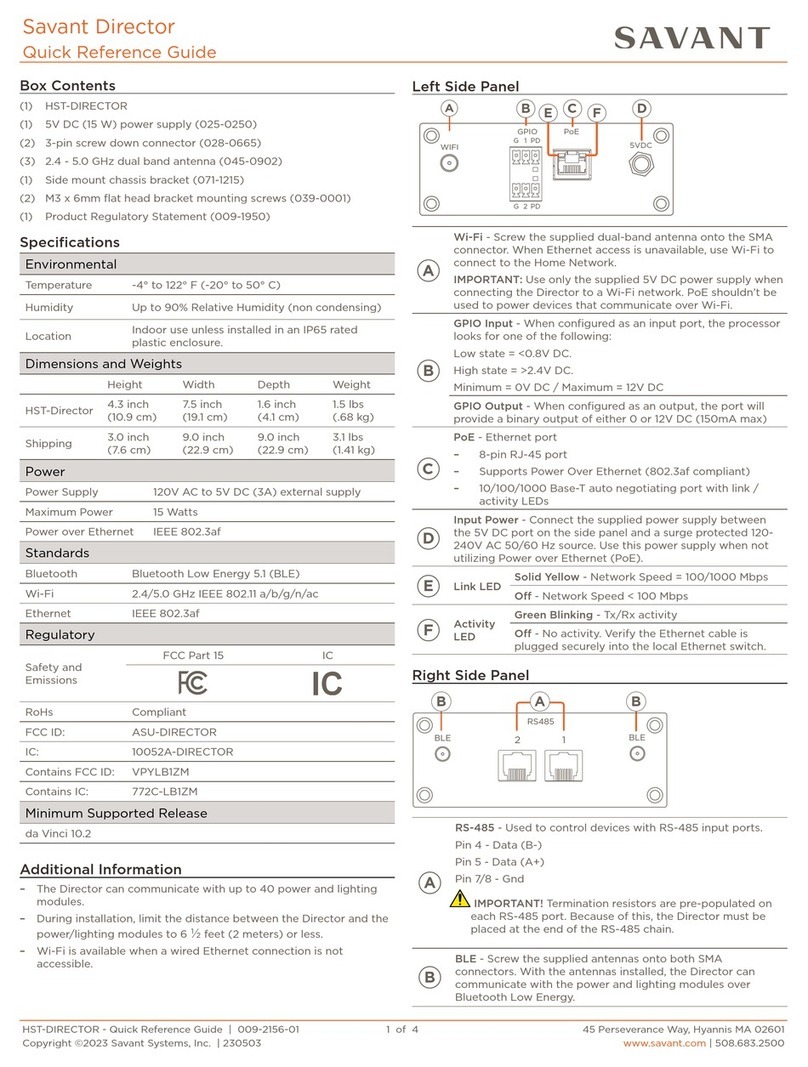
Savant HST-4001 User manual

Savant
Savant QO PBC-1000-10 Quick reference guide
Savant
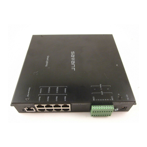
Savant SmartLighting SSL-P018 User manual
Savant
Savant WIF S104 Series User manual
Savant
Savant SSC-0008 User manual
Savant
Savant SmartControl 12 User manual
Savant
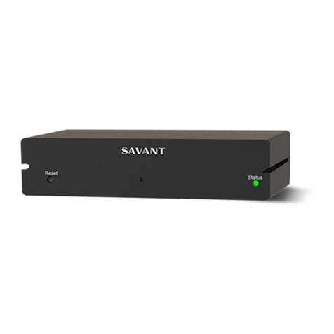
Savant WIF 104 Series User manual
Savant
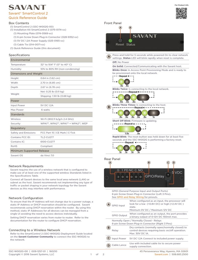
Savant CPT-1212 User manual
Savant
Savant SmartControl 2 User manual

Savant
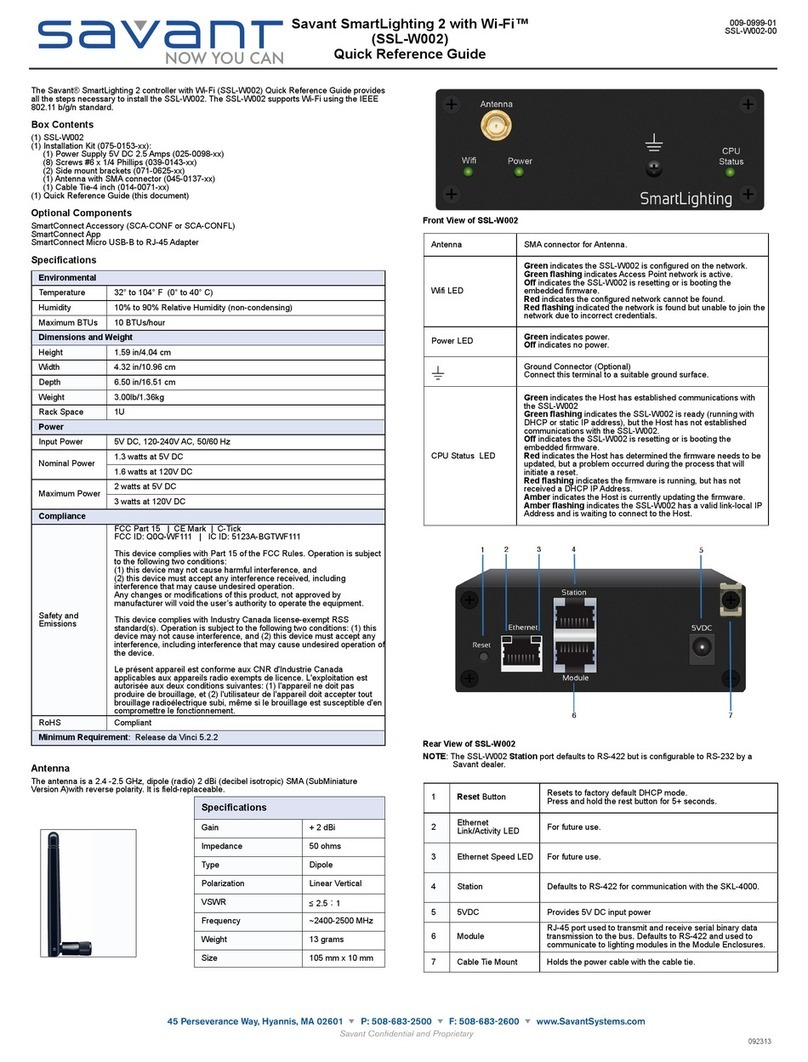
Savant SmartLighting SSL-W002 User manual

Savant
Savant ICC-TP00 User manual

Savant
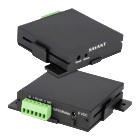
Savant SmartControl 12 Quick reference guide
Savant
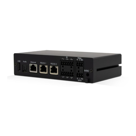
Savant SmartControl SSC-W003I User manual
Savant
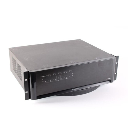
Savant S2 Quick reference guide
Savant
Savant SmartMediaPro 6 Quick reference guide
Savant
Savant SmartControl SSC-W002G User manual
Savant
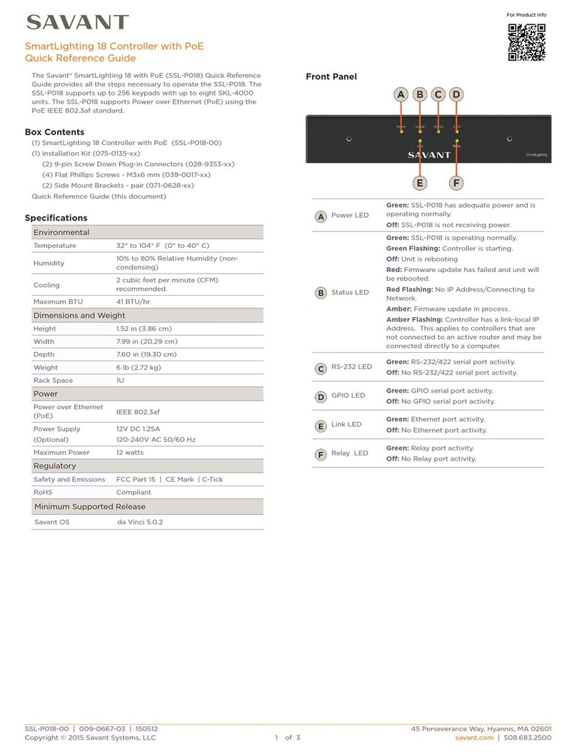
Savant SmartLighting 18 User manual

Savant
Savant CPT-1212 User manual
Savant
Savant SmartControl SSC-W02R User manual
Savant
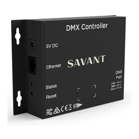
Savant LCB-DMX1 Quick reference guide
Popular Controllers manuals by other brands

Digiplex
Digiplex DGP-848 Programming guide

YASKAWA
YASKAWA SGM series user manual

Sinope
Sinope Calypso RM3500ZB installation guide

Isimet
Isimet DLA Series Style 2 Installation, Operations, Start-up and Maintenance Instructions

LSIS
LSIS sv-ip5a user manual

Airflow
Airflow Uno hab Installation and operating instructions
