5
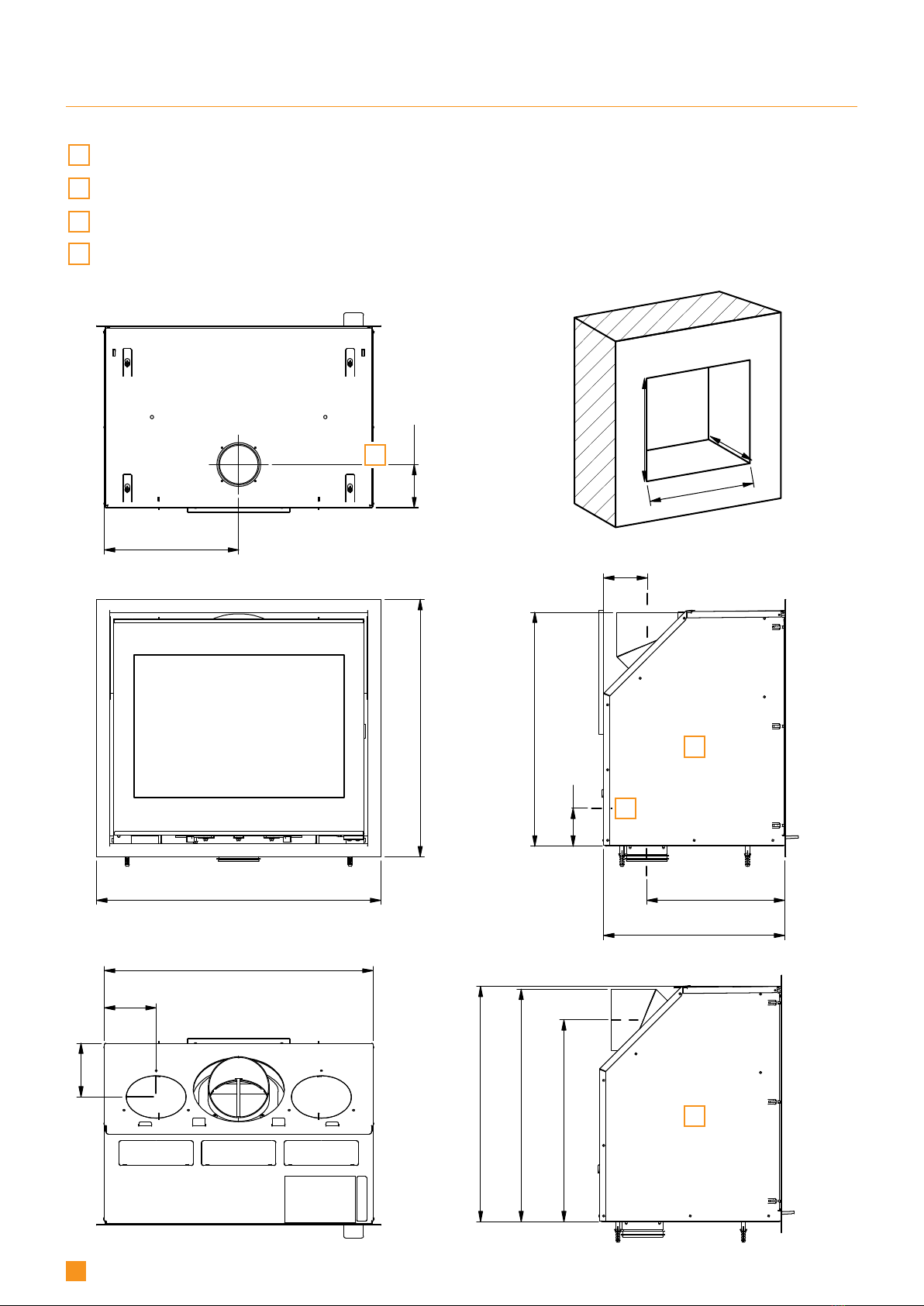
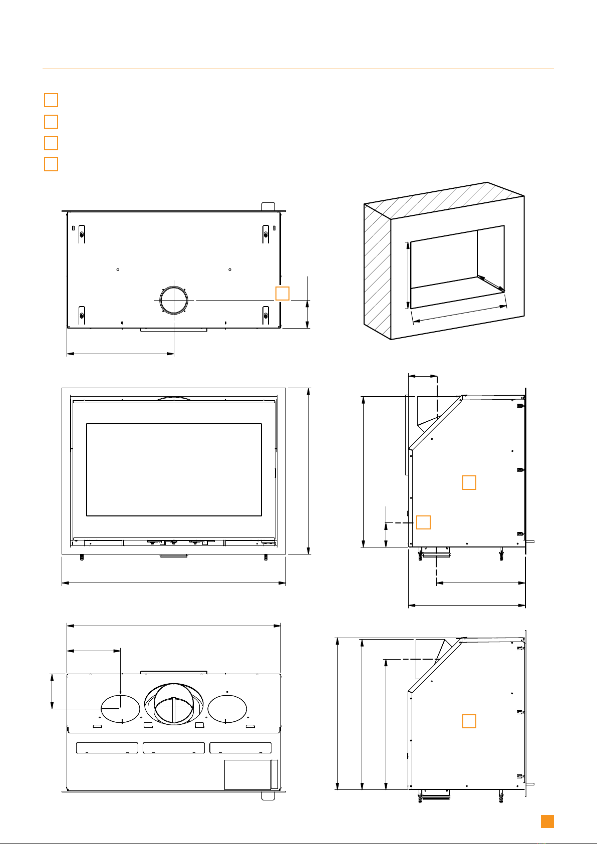
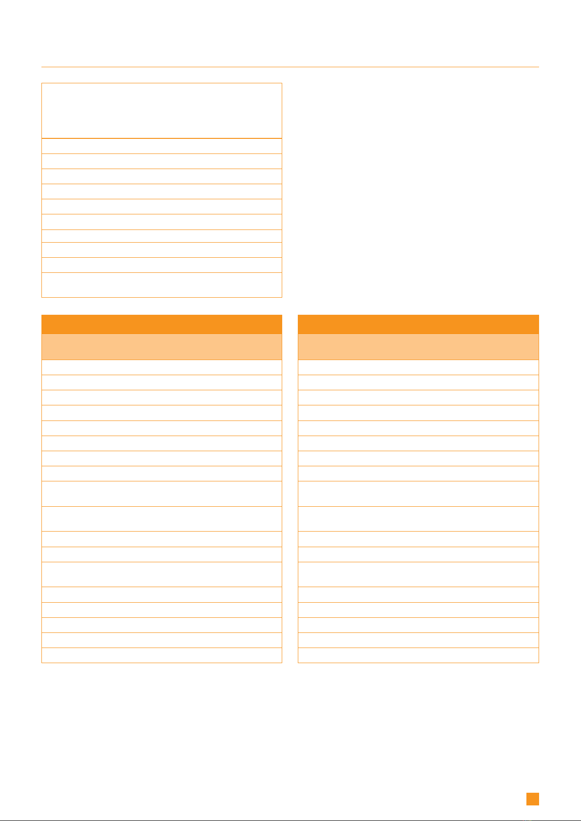
TECHNICAL DATA AND DIMENSIONS
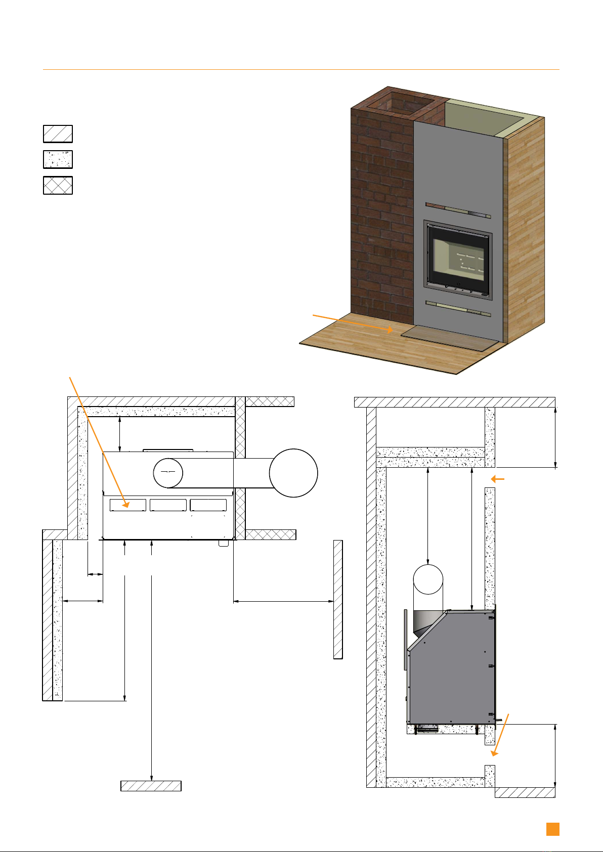
Materials
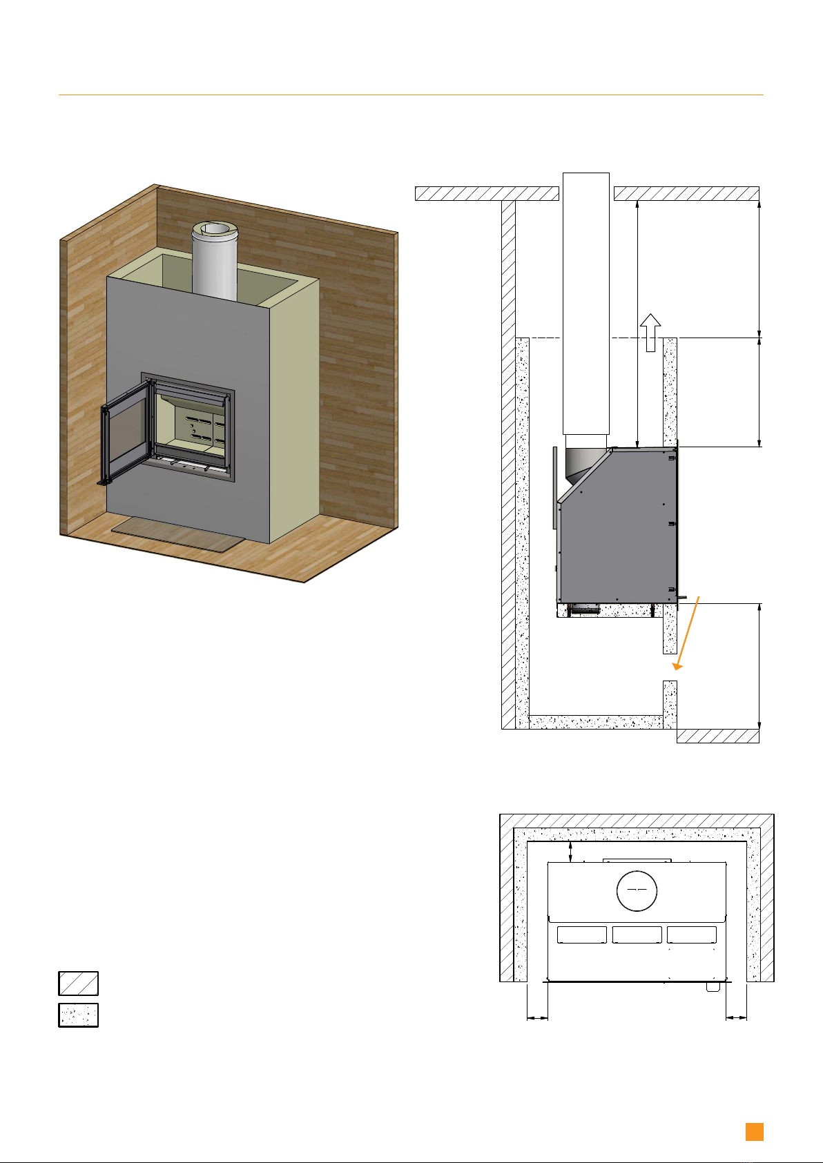
Steel plate
Galvanised sheet
Ceramic stone/vermiculite
Chamotte
Robax glass
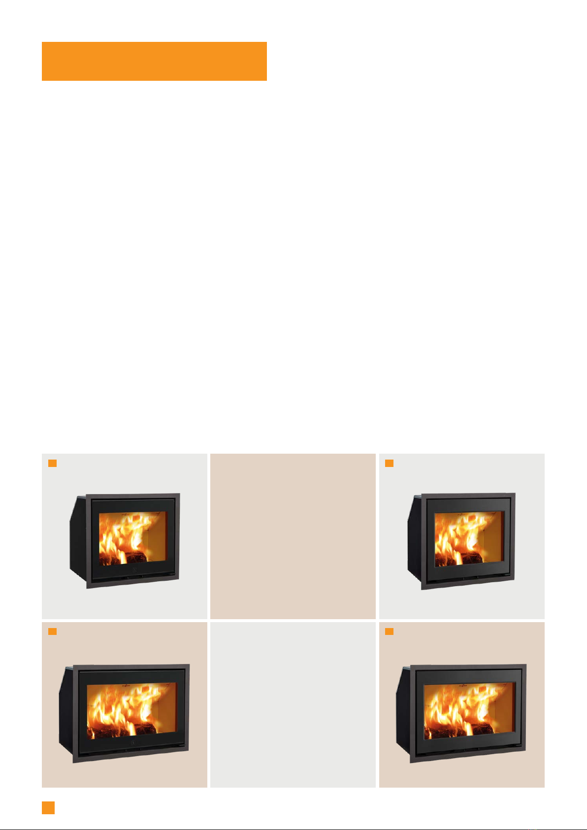
Scan 1003 – Test in compliance with EN 13229
Combustion chamber Ceramic
stone
Vermi-
culite
CO Emission at 13% O20,09 0,07 %
CO Emission at 13% O21148 832 mg/Nm3
Dust @ 13% O229 27 mg/Nm3
Nox@ 13% O295 95 mg/Nm3
Efficiency 81 80 %
Energy efficiency index 108 105
Energy efficiency class A+ A
Nominel output 7,2 7,2 kW
Chimney temperature
EN 13229 242 260 °C
Temperature in flue conn.
piece 290 312 °C
Amount of smoke 7,4 7,4 g/sec
Sub-pressure EN 13229 12 12 Pa
Recommended sub-pressure
in connecting piece 16-18 16-18 Pa
Required combustion air supply 22,5 22 m3/h
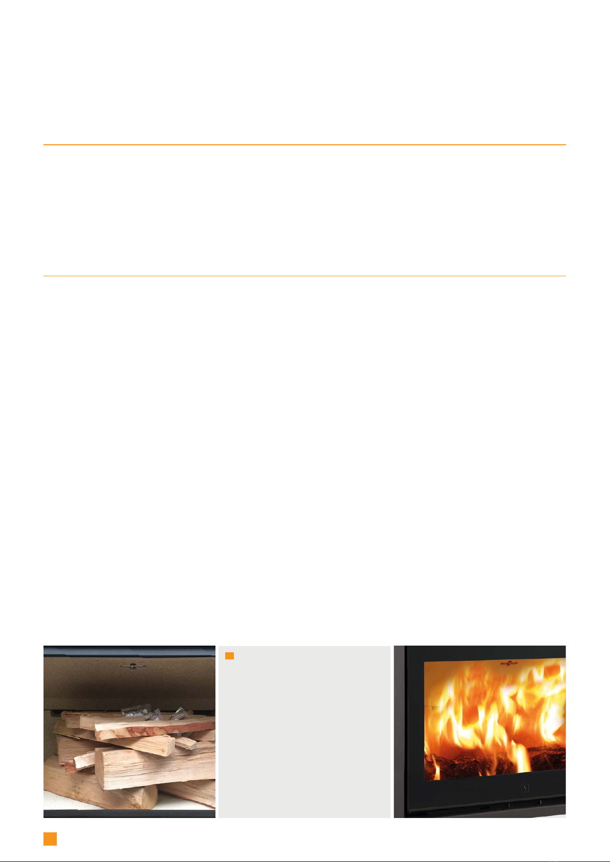
Fuel Wood Wood
Fuel consumption 2,4 2,4 kg/h
Amount of fuel required to light 2 2 kg
Amount of fuel, max. 3 3 kg
* Intermittent operation in this context means normal use of
a wood-burning stove. In other words, you should let the fire
die down until only the embers are left before refuelling.
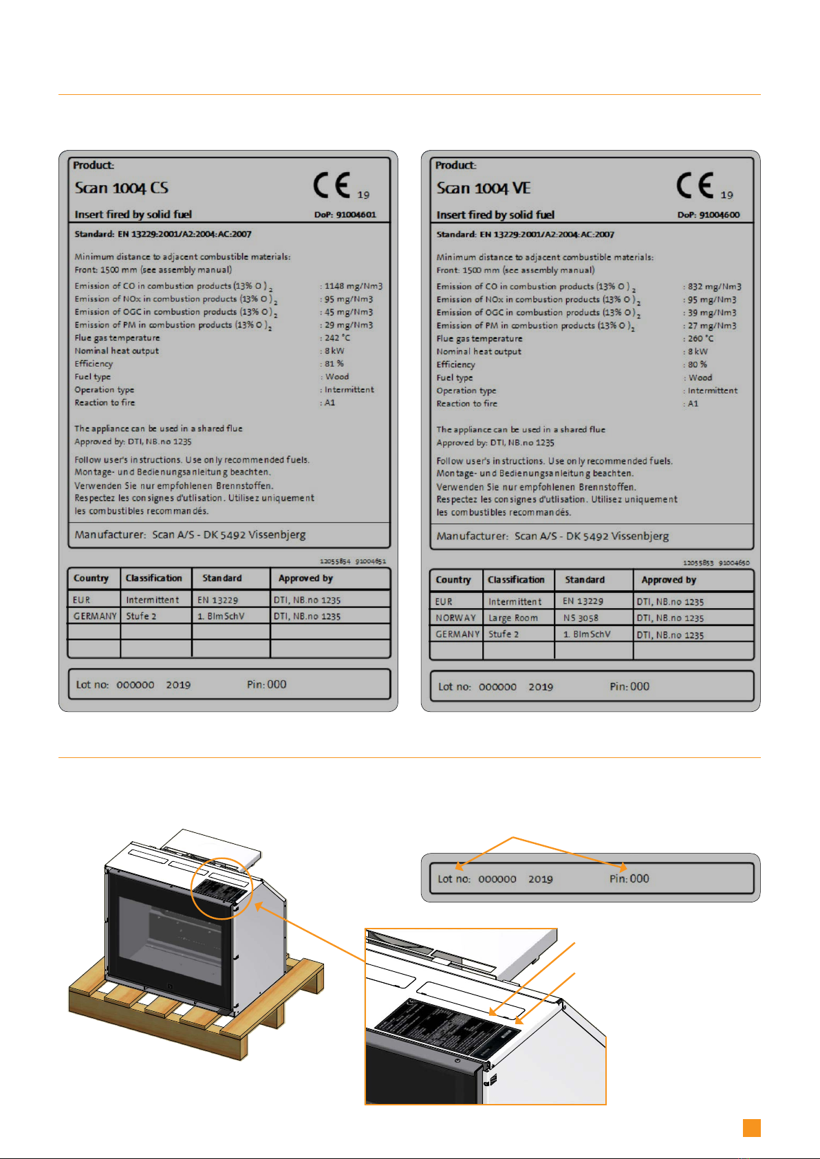
Scan 1003-1004 is produced in accordance with type
approval for the product, which also covers the product’s
Assembly and Instruction Manual.
The Declaration of Performance (DoP) is available from
www.scan-stoves.com
Surface treatment Senotherm
Max. wood length Scan 1003 50 cm
Max. wood length Scan 1004 65 cm
Weight Scan 1003 (Ceramic stone) ca. 124 kg
Weight Scan 1003 (Vermiculite) ca. 106 kg
Weight Scan 1004 (Ceramic stone) ca. 129 kg
Weight Scan 1004 (Vermiculite) ca. 112 kg
Connecting piece internal diameter 144 mm
Connecting piece external diameter 148 mm
Approval type Intermittent
fuelling*
EN 13229 was carried out on the installation shown on page 13.
Scan 1004 – Test in compliance with EN 13229
Combustion chamber Ceramic
stone
Vermi-
culite
CO Emission at 13% O20,09 0,07 %
CO Emission at 13% O21148 832 mg/Nm3
Dust @ 13% O229 27 mg/Nm3
Nox@ 13% O295 95 mg/Nm3
Efficiency 81 80 %
Energy efficiency index 108 105
Energy efficiency class A+ A
Nominel output 8 8 kW
Chimney temperature
EN 13229 242 260 °C
Temperature in flue conn.
piece 290 312 °C
Amount of smoke 7,4 7,4 g/sec
Sub-pressure EN 13229 12 12 Pa
Recommended sub-pressure
in connecting piece 16-18 16-18 Pa
Required combustion air supply 22,5 22 m3/h
Fuel Wood Wood
Fuel consumption 2,4 2,4 kg/h
Amount of fuel required to light 2 2 kg
Amount of fuel, max. 3 3 kg