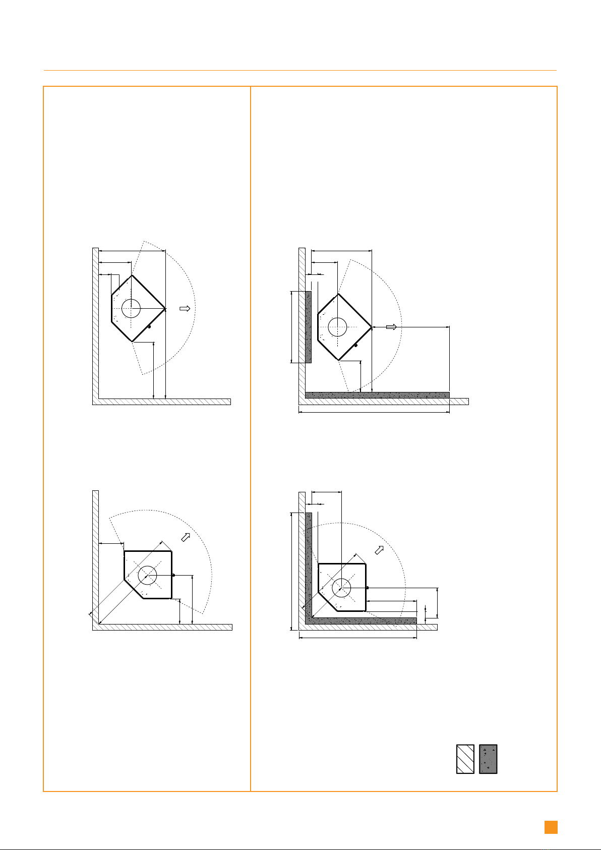
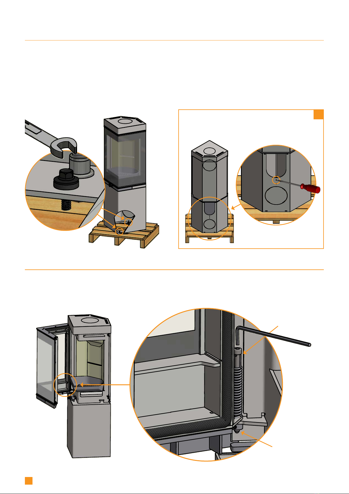
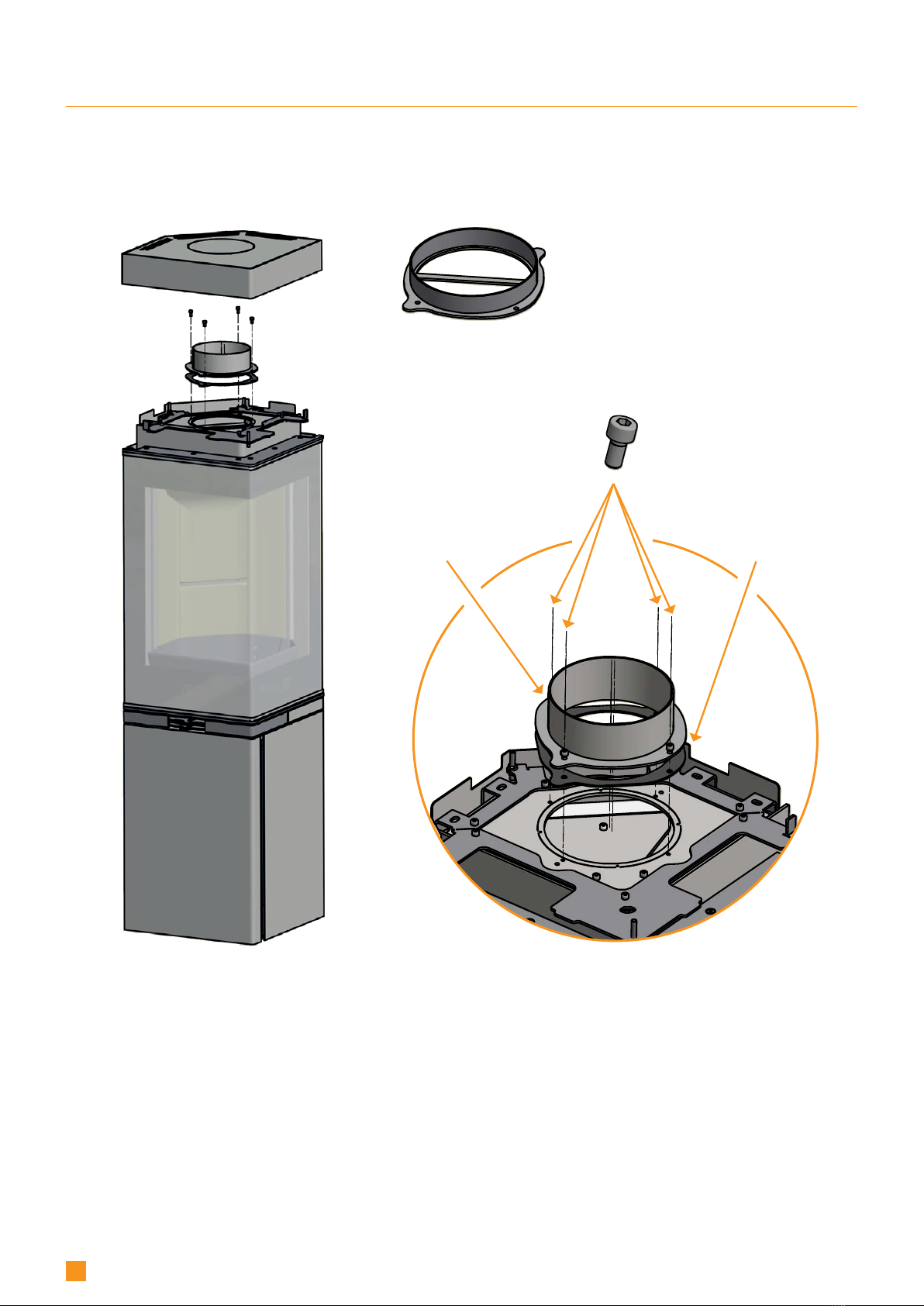
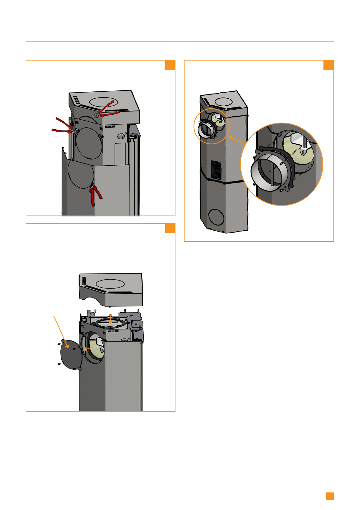
SCAN 80 User guide

80
ASSEMBLY AND INSTRUCTIONS MANUAL SCAN 80
UK
SCAN
UK - ASSEMBLY AND INSTRUCTIONS MANUAL
SCAN
80

80
2
UK
SCAN
You have purchased a product by one of Europe’s leading manufacturers of
wood-burning stoves, and we are sure that you will have years of pleasure from your
purchase.
To make the best possible use of your stove, it is important that you
follow our advice and instructions. Read through this Assembly and Instruction
Manual carefully before you start to assemble your stove.
SCAN 80-3
HIGH TOP
CLOSED BASE
SCAN 80-4C
(CORNER)
HIGH TOP
BASE WITH DOOR
SCAN 80-4
HIGH TOP
BASE WITH DOOR
SCAN 80-3C
(CORNER)
HIGH TOP
CLOSED BASE
SCAN 80-1
CLOSED BASE
SCAN 80-2
BASE WITH DOOR
CONGRATULATIONS
ON YOUR NEW SCAN
WOOD-BURNING STOVE

3
CONTENTS
¬¬
MOUNTING THE UK - BLOCKING AND SCREW 29
¬¬
TECHNICAL DATA 4
Installation 4
Safety 4
The Clean Air Act 1993 and Smoke Control Areas 4
Technical data and dimensions 5
Dimension sketch and minimum distances 6
Type plate 8
Product registration umber 8
¬¬
ASSEMBLY 9
Tools for the mounting of the woodburning stove 9
Loose parts 9
Additional accessories 9
Disposal of packaging 9
Fresh air intake 9
Closed combustion system 10
Existing chimney and pre-fabricated element chimney 10
Connection between stove and steel chimney 10
Requirements for chimney 11
Positioning the stove at a non-flammable wall 11
Distance to furniture 11
Safety distance 11
Removal of the stove from the pallet 12
Door (Self-closing) 12
Height adjustment of stove 13
Fitting the flue connection piece 14
Heat-storage system 16
Load-bearing foundation 17
Floor plate 17
¬¬
INSTRUCTIONS FOR USE 18
CB-technology (Clean Burn) 18
Baffle plate 18
Ash container 18
Primary air 18
Secondary air 18
Adjustment of primary- and secondary air 19
¬¬
INSTRUCTIONS FOR HEATING 20
Environmentally friendly operation 20
Lighting 20
”Top down” lighting 20
Continuous operation 21
Warning about over-firing 21
Using the stove in various weather conditions 22
Firing in the spring or autumn 22
The function of the chimney 22
Chimney fire 22
General notes 22
¬¬
HANDLING OF THE FUEL 23
Selecting wood/fuel 23
Preparation 23
Storing 23
Moisture 23
Use of the following as fuel is illegal 23
Calorific value of the wood 23
¬¬
MAINTAINANCE 24
Sweeping the chimney and cleaning the stove 24
Checking the stove 24
Servicing 24
Combustion chamber lining 24
Gaskets 24
Painted surfaces 24
Cleaning the glass 25
Removing the baffle plate and the baffle unit 25
Disposal of stove parts 26
¬¬
TROUBLESHOOTING 27
¬¬
WARRANTY 28

4
TECHNICAL DATA
INSTALLATION
¬ The house owner is responsible for ensuring that installation and assembly are in accordance with national and local building
regulations as well as the information provided in this Assembly and Instructions Manual
¬ When you install any kind of fireplace or stove, you must inform the local building and housing authorities. In addition you are
obliged to have the installation inspected and approved by a local chimney sweep prior to commissioning
¬ To ensure best-possible functionality and safety for your installation, we advise you to call a professional fitter. Your Scan
dealer will be able to recommend a qualified fitter in your area. For information on Scan Dealers, please go to
www.scan-stoves.com
SAFETY
Any changes made to the product by the dealer, fitter or user could result in the product and safety functions not functioning as
intended. The same applies to the fitting of accessories or extra equipment not supplied by Scan A/S. This could also be the case
if parts that are necessary for the operation and safety of the stove are dismantled or removed.
THE CLEAN AIR ACT 1993 AND SMOKE CONTROL AREAS
Under the Clean Air Act local authorities may declare the whole or part of the district of the authority to be a smoke control area.
It is an offence to emit smoke from a chimney of a building, from a furnace or from any fixed boiler if located in a designated smoke
control area. It is also an offence to acquire an "unauthorized fuel" for use within a smoke control area unless it is used in an
"exempt" appliance ("exempted" from the controls which generally apply in the smoke control area).
The Secretary of State for Environment, Food and Rural Affairs has powers under the Act to authorize smokeless fuels or
exempt appliances for use in smoke control areas in England. In Scotland and Wales this power rests with Ministers in the
devolved administrations for those countries. Separate legislation, the Clean Air (Northern Ireland) Order 1981, applies in
Northern Ireland. Therefore it is a requirement that fuels burnt or obtained for use in smoke control areas have been
"authorized" in Regulations and that appliances used to burn solid fuel in those areas (other than "authorized" fuels) have been
exempted by an Order made and signed by the Secretary of State or Minister in the devolved administrations.
¬ Further information on the requirements of the Clean Air Act can be found here: www.smokecontrol.defra.gov.uk
¬ Your local authority is responsible for implementing the Clean Air Act 1993 including designation and supervision of smoke
control areas and you can contact them for details of Clean Air Act requirements”
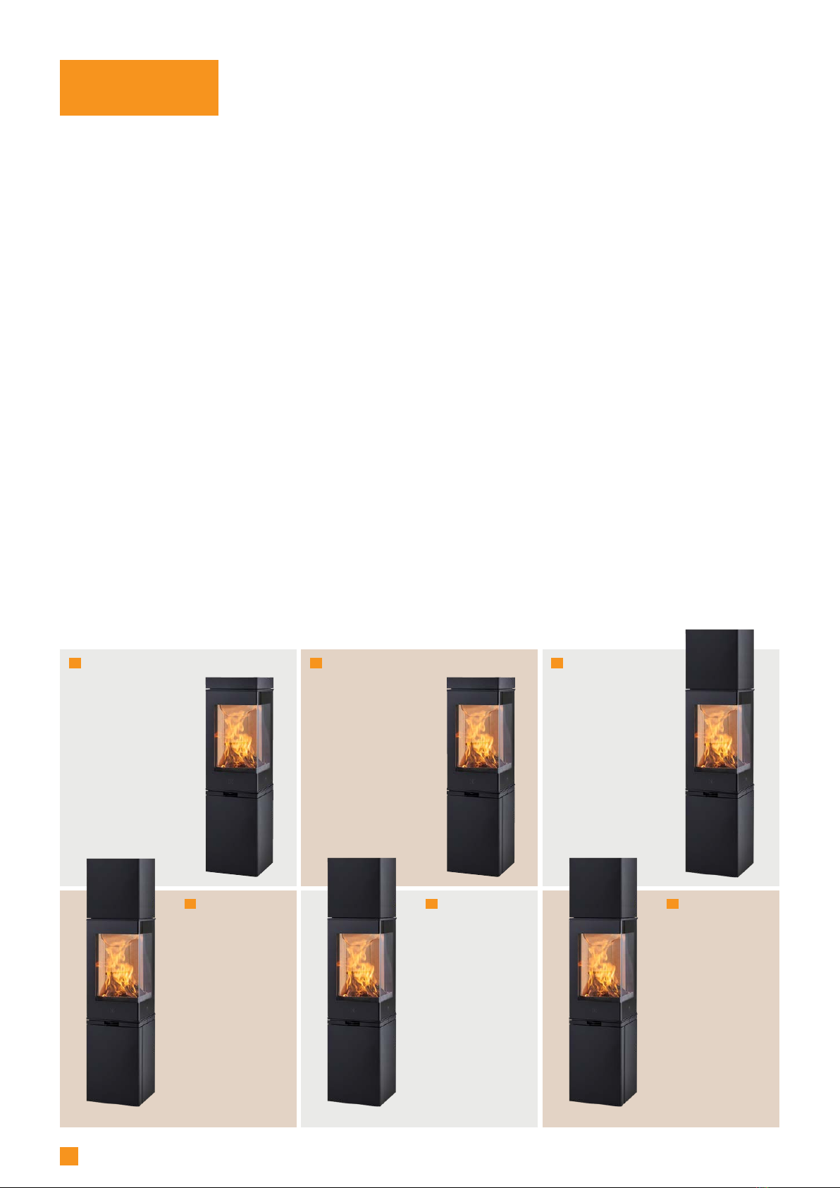
¬ The Scan 80-1, 80-2, 80-3, 80-4, 80-3C and 80-4C have been recommented as suitable for use in smoke control areas when burning
wood logs and when fitted with a mechanical stop to prevent that the secondary air valve cannot be closed lower than 868 mm2
¬ The secondary air valve has been modified, so that is does not close completely but has an opening corresponding to the
position used at the lowest emission test
¬ You can use any type of wood as fuel
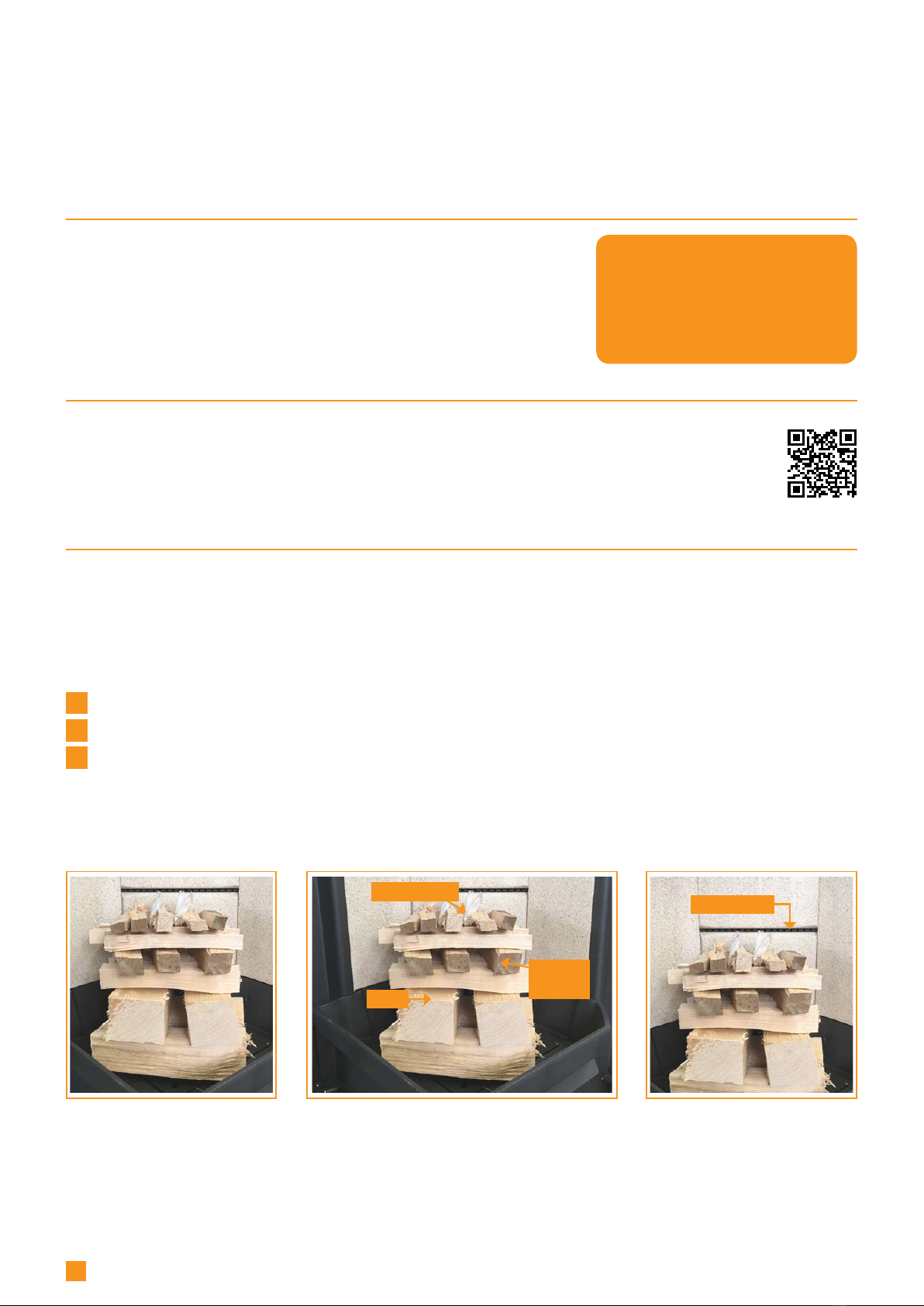
YOU ACHIEVE AN OPTIMAL
BENEFIT OF THE STOVE BY
FOLLOWING THE ADVICE
GIVEN UNDER:
"INSTRUCTIONS FOR HEATING"
PLEASE NOTE!

5
* The stove can take logs up to 30 cm (horizontally placed).
** Intermittent operation in this context means normal use of
a wood-burning stove. In other words, you should let the fire
die down until only the embers are left before refuelling.
The Scan 80-series is produced in accordance with type
approval for the product, which also covers the product’s
Assembly and Instruction Manual.
The Declaration of Performance (DoP) is available from
www.scan-stoves.com
Tested in accordance with EN 13240
CO Emission at 13% O20,06 %
CO Emission at 13% O2800 mg/Nm3
Dust @ 13% O2<6 mg/Nm3
Nox@ 13% O281 mg/Nm3
Efficiency 84 %
Energy efficiency index 112
Energy efficiency class A+
Nominal output 6 kW
Chimney temperature EN 13240 195 °C
Temperature in flue conn. piece 233 °C
Amount of smoke 6,3 g/sec
Negative pressure EN 13240 12 Pa
Recommended negative pressure
in flue connecting piece 17-20 Pa
Required combustion air supply 19-25 m3/h
Fuel Wood
Fuel consumption 1,9 kg/h
Amount of fuel required to light 1,5 kg
Amount of fuel, max. 2,25 kg
Materials
Steel plate
Cast iron
Galvanised sheet
Vermiculite
Surface treatment Senotherm
Max. log length 25 cm*
Weight Scan 80-1/2 ca. 104,4 kg
Weight Scan 80-3/4 ca. 110,0 kg
Flue conn. piece internal diameter 144 mm
Flue conn. piece external diameter 148 mm
Fresh air connection piece
external diameter 100 mm
Approval type Intermittent**
TECHNICAL DATA AND DIMENSIONS
EN test was carried out on the installation with an un-insulated
elbow pipe shown in the assembly manual for Scan 1008 on
page 11.
(Reference to EN 13240: 2001/A2:2004)

Stove:
Path:
Articlenumber:
Material:
Date:
Constructed/Changed by:
SCAN A/S
DK-5492 Vissenbjerg©
Drawing
number:
Name:
C:\Working Folder\Designs\Scan 80\90580024.idw
90580024
Målskitse scan 80-3/4 08-11-2021
jwa
Scan 80
Weight: Area:
891,54 kg 67573034 mm^2
154
1349
385
385
545
1374
183
153
398
1567
25
1670
183
NAVN:
STI:
DIMENSION:
MATERIALE: DATO: SIGN:
Krog Iversen & Co A/S
DK-5492 Vissenbjerg©
TG.NR:EMNE:
C:\Working Folder\Designs\Scan 84\90184008.idw
90184008
Opstillingstegning (afstand til brændbart materiale)
23-06-2020 KEN
Scan 84
VÆGT:
AREAL:
N/A
N/A
Y
X
900**
900
900
360°
NAVN:
STI:
DIMENSION:
MATERIALE: DATO: SIGN:
Krog Iversen & Co A/S
DK-5492 Vissenbjerg©
TG.NR:EMNE:
C:\Working Folder\Designs\Scan 84\90184009.idw
90184009
Opstillingstegning (afstand til brændbart materiale)
30-11-2020 KEN
Scan 84
VÆGT:
AREAL:
N/A
N/A
750
Stove:
Path:
Articlenumber:
Material:
Date:
Constructed/Changed by:
SCAN A/S
DK-5492 Vissenbjerg©
Drawing
number:
Name:
C:\Working Folder\Designs\Scan 80\90580023.idw
90580023
Målskitse scan 80-1/2 08-11-2021
jwa
Scan 80
Weight: Area:
891,54 kg 67573034 mm^2
1206
154
183
153
1349
1351
385
385
193
193
153
545
183
800
350
***
***
*
*
*
*
Stove:
Path:
Articlenumber:
Material:
Date:
Constructed/Changed by:
SCAN A/S
DK-5492 Vissenbjerg©
Drawing
number:
Name:
C:\Working Folder\Designs\Scan 80\90580023.idw
90580023
Målskitse scan 80-1/2 08-11-2021
jwa
Scan 80
Weight: Area:
891,54 kg 67573034 mm^2
1206
154
183
153
1349
1351
385
385
193
193
153
545
183
*
*
Stove:
Path:
Articlenumber:
Material:
Date:
Constructed/Changed by:
SCAN A/S
DK-5492 Vissenbjerg©
Drawing
number:
Name:
C:\Working Folder\Designs\Scan 80\90580024.idw
90580024
Målskitse scan 80-3/4 08-11-2021
jwa
Scan 80
Weight: Area:
891,54 kg 67573034 mm^2
154
1349
385
385
545
1374
183
153
398
1567
25
1670
183
6
DIMENSION SKETCH AND MINIMUM DISTANCES
Flammable ceiling
All distances are in mm.
All distances are minimum distances
* Connection of fresh-air intake - external diameter Ø 100 mm
** Min. distance to furniture/flammable material
*** Height to the beginning of flue connecting piece at top outlet
Floor plate
X / Y according to national laws and regulations
Flammable material
Radiation zone
Scan 80-1 and Scan 80-2 Scan 80-3 and Scan 80-4

Stove:
Path:
Articlenumber:
Material:
Date:
Constructed/Changed by:
SCAN A/S
DK-5492 Vissenbjerg©
Drawing
number:
Name:
C:\Working Folder\Designs\Scan 80\90580009B.idw
90580009B
Afstand brandmur, Isoleret start, parallel 21-04-2021
KEN
Scan 80
Weight: Area:
N/A N/A
50
Møbleringsafstand: 800 mm.
Brandbart materiale
Brandmur
250
570
617
1200
208
482
516
900
900
360°
NAVN:
STI:
DIMENSION:
MATERIALE: DATO: SIGN:
Krog Iversen & Co A/S
DK-5492 Vissenbjerg©
TG.NR:EMNE:
C:\Working Folder\Designs\Scan 87\90087007.idw
90087007
Opstillingstegning (afstand til brandmur)
02-02-2021 KEN
Scan 87
VÆGT:
AREAL:
N/A
N/A
500
304
680
1480
1693
800
50
NAVN:
STI:
DIMENSION:
MATERIALE: DATO: SIGN:
Krog Iversen & Co A/S
DK-5492 Vissenbjerg©
TG.NR:EMNE:
C:\Working Folder\Designs\Scan 87\90087007.idw
90087007
Opstillingstegning (afstand til brandmur)
02-02-2021 KEN
Scan 87
VÆGT:
AREAL:
N/A
N/A
500
304
680
1480
1693
800
50
Stove:
Path:
Articlenumber:
Material:
Date:
Constructed/Changed by:
SCAN A/S
DK-5492 Vissenbjerg©
Drawing
number:
Name:
C:\Working Folder\Designs\Scan 80\90580007B.idw
90580007B
Afst.brændbar væg, hjørne, Isol.+ Uisol. start 21-04-2021
KEN
Scan 80
Weight: Area:
N/A N/A
200
Møbleringsafstand: 800 mm.
Brandbart materiale
559,5
833
200
388
Stove:
Path:
Articlenumber:
Material:
Date:
Constructed/Changed by:
SCAN A/S
DK-5492 Vissenbjerg©
Drawing
number:
Name:
C:\Working Folder\Designs\Scan 80\90580008B.idw
90580008B
Afst. brændbar væg, parallel, isoleret start 21-04-2021
Ken
Scan 80
Weight: Area:
N/A N/A
100
Møbleringsafstand: 800 mm.
Brandbart materiale
450
258
532
716
Stove:
Path:
Articlenumber:
Material:
Date:
Constructed/Changed by:
SCAN A/S
DK-5492 Vissenbjerg©
Drawing
number:
Name:
C:\Working Folder\Designs\Scan 80\90580005B.idw
90580005B
Afstand brandmur, Isoleret start, hjørne 21-04-2021
KEN
Scan 80
Weight: Area:
N/A N/A
400
50
50
Møbleringsafstand: 800 mm.
Brandbart materiale
Brandmur
238
238
336
610
935
935
*
*
7
MINIMUM DISTANCES
Flammable material
Fire wall, e.g. 50 mm Jøtul Firewall, 110 mm brick
or other material with corresponding fireproof and
insulating abilities
All distances are in mm.
All distances are minimum distances
These distances apply for an insulated flue pipe, all the way down to the stove
* Distance to glass
Minimum distance to flammable materials
Minimum distance to flammable wall protected by a fire wall

Stove:
Path:
Articlenumber:
Material:
Date:
Constructed/Changed by:
SCAN A/S
DK-5492 Vissenbjerg©
Drawing
number:
Name:
C:\Working Folder\Designs\Scan 80\90580031.idw
90580031
Placering af typeskilt 17-05-2017
sr
Scan 80
Weight: Area:
N/A N/A
8
PRODUCT REGISTRATION UMBER
All Scan wood-burning stoves are provided with a product registration number. Please make a note of this number at the rear
page of this manual; you will always need to quote it when contacting your dealer or Scan A/S.
The product registration number is located at the rear of the stove.
TYPE PLATE
All Scan wood-burning stoves are fitted with a type plate that specifies the approval standards and the distance to flammable
materials.
The type plate is located at the rear of the stove.
Type plate Scan 80
Product registration number
Type plate
Product
registration
number

9
ASSEMBLY
TOOLS FOR THE MOUNTING OF THE WOODBURNING STOVE
¬Spirit level ¬4 mm Allen key
¬Cutting nippers ¬Crosstip screwdriver
¬Flat head screwdriver
LOOSE PARTS
The following loose parts are located in the stove's combustion chamber:
¬ Oven mitt ¬ Two flue connection pieces (int. and ext. flue pipe)
¬ Gasket for flue connecting piece ¬ Screws for fastening the flue connection piece
¬ Ash container ¬ UK-blocking and screw
¬ Eco energy label
ADDITIONAL ACCESSORIES
¬ Small shaped floor plate in clear or smoke-coloured glass ¬ Large shaped floor plate in clear or smoke-coloured
¬ Heat-storage stones for High Top glass
DISPOSAL OF PACKAGING
Your Scan stove may come supplied with the following packaging:
Wood packaging The wood packaging can be reused and after final use can be incinerated as a CO2neutral
product or sent for recycling
Foam Send for recycling or waste disposal
Plastic bags Send for recycling or waste disposal
Stretch/plastic film Send for recycling or waste disposal
FRESH AIR INTAKE
In a well-insulated house the air used for the combustion process has to be replaced. This particularly applies to houses with
mechanical ventilation. There are different ways of making sure that air is exchanged. The most important thing is to ensure that
there is a supply of air to the room where the wood stove is located. The external wall vent must be located as close to the wood
stove as possible, and you must be able to close it when you are not using the stove.
National and local building regulations must be followed with regard to connection of a fresh air intake.

F ( 1 : 8 ) G ( 1 : 8 )
F
G
Stove:
Path:
Articlenumber:
Material:
Date:
Constructed/Changed by:
SCAN A/S
DK-5492 Vissenbjerg©
Drawing
number:
Name:
C:\Working Folder\Designs\Scan 80\90580029.idw
90580029
ekstern forbrændingsluft 16-05-2017
jwa
Scan 80
Weight: Area:
N/A N/A
Ø170mm.
F ( 1 : 8 ) G ( 1 : 8 )
F
G
Stove:
Path:
Articlenumber:
Material:
Date:
Constructed/Changed by:
SCAN A/S
DK-5492 Vissenbjerg©
Drawing
number:
Name:
C:\Working Folder\Designs\Scan 80\90580029.idw
90580029
ekstern forbrændingsluft 16-05-2017
jwa
Scan 80
Weight: Area:
N/A N/A
Ø170mm.
F ( 1 : 8 ) G ( 1 : 8 )
F
G
Stove:
Path:
Articlenumber:
Material:
Date:
Constructed/Changed by:
SCAN A/S
DK-5492 Vissenbjerg©
Drawing
number:
Name:
C:\Working Folder\Designs\Scan 80\90580029.idw
90580029
ekstern forbrændingsluft 16-05-2017
jwa
Scan 80
Weight: Area:
N/A N/A
Ø170mm.
F ( 1 : 8 ) G ( 1 : 8 )
F
G
Stove:
Path:
Articlenumber:
Material:
Date:
Constructed/Changed by:
SCAN A/S
DK-5492 Vissenbjerg©
Drawing
number:
Name:
C:\Working Folder\Designs\Scan 80\90580029.idw
90580029
ekstern forbrændingsluft 16-05-2017
jwa
Scan 80
Weight: Area:
N/A N/A
Ø170mm.
10
CLOSED COMBUSTION SYSTEM
You should use the closed combustion system for the wood-burning stove if you live in a newly-built, airtight home. External
combustion air is connected through a ventilation pipe via the wall or floor.
We recommend mounting a valve in the ventilation pipe in order to avoid condensate in the stove and the pipe system, which can
be closed when the oven is not in use. It can also be an advantage to insulate the ventilation pipe.
Minimum Ø 100 mm ventilation pipe, maximum length: 6 metres with a maximum of one bend.
If you want external combustion air at the rear, you must close the hole in the bottom with the dismounted cover plate.
NOTE: if the stove has a fresh air connexion or closed combustion, the ventilation pipe must be open, when the stove is in use!
EXISTING CHIMNEY AND PRE-FABRICATED ELEMENT CHIMNEY
If you intend to connect your stove to an existing chimney, it makes sense to contact an authorised Scan dealer, or a local
chimney sweep, for advice. These experts will also let you know if your chimney needs renovating.
¬ When connecting a pre-fabricated element chimney, follow the manufacturer’s connection instructions for the relevant
chimney type
CONNECTION BETWEEN STOVE AND STEEL CHIMNEY
Your Scan dealer, or local chimney sweep, can advise you on choosing a make and type of steel chimney. This ensures that the
chimney will match your wood-burning stove.
External combustion air is
connected at the con-
nection piece under the
combustion chamber.
If you want external combustion
air via floor or wall, remove the
cover plate with a pair of cutting
pliers

Stove:
Path:
Articlenumber:
Material:
Date:
Constructed/Changed by:
SCAN A/S
DK-5492 Vissenbjerg©
Drawing
number:
Name:
C:\Working Folder\Designs\Scan 80\90580075.idw
90580075Scan 80 med knærør 10-09-2018
ken
Scan 80
Weight: Area:
N/A N/A
11
REQUIREMENTS FOR CHIMNEY
The chimney must have a minimum internal diameter of 148 mm and have a T400 designation,
with G for the soot fire test. The length should be min. 4 metres.
If you opt to connect the stove with an elbow pipe, you should use a curved elbow,
as this gives a better draught.
If you connect the stove with a sharp elbow pipe, the cleansing lid must be placed in the
vertical part so that the horizontal part can be cleaned through here.
If the chimney is fitted with a smoke extractor, it must be possible to adjust it to a suitable draft.
The requirements to the chimney and the flue pipe in terms of safety distances must be met.
¬ Choosing the wrong length or diameter of steel chimney could impair functionality
¬ Always comply exactly with the instructions provided by the steel chimney supplier
POSITIONING THE STOVE AT A NON-FLAMMABLE WALL
There are no demands concerning the distance to non-flammable materials, but we recommend a distance of 50 mm in order to
facilitate the cleaning of the stove, the flue pipes and the chimney and to prevent possible damages to the wall.
DISTANCE TO FURNITURE
Distance to furniture: min. 800 mm.
You should however assess whether furniture or other items might become excessively dry due to being too close to the stove.
Distance to ceiling (High Top): 350 mm.
SAFETY DISTANCE
European, national and local regulations concerning safety distances for wood-burning stoves must be complied with.

A
Stove:
Path:
Articlenumber:
Material:
Date:
Constructed/Changed by:
SCAN A/S
DK-5492 Vissenbjerg©
Drawing
number:
Name:
C:\Working Folder\Designs\Scan 80\90580025B.idw
90580025B
Afmontering fra Palle 12-04-2021
KEN
Scan 80
Weight: Area:
N/A N/A
1
A ( 0,13 : 1 )
B ( 1:2 )
C ( 1:2 )
A
Stove:
Path:
Articlenumber:
Material:
Date:
Constructed/Changed by:
SCAN A/S
DK-5492 Vissenbjerg©
Drawing
number:
Name:
C:\Working Folder\Designs\Scan 80\90580025.idw
90580025
Afmontering fra Palle 10-05-2017
jwa
Scan 80
Weight: Area:
N/A N/A
A ( 0,13 : 1 )
B ( 1:2 )
C ( 1:2 )
A
Stove:
Path:
Articlenumber:
Material:
Date:
Constructed/Changed by:
SCAN A/S
DK-5492 Vissenbjerg©
Drawing
number:
Name:
C:\Working Folder\Designs\Scan 80\90580025.idw
90580025
Afmontering fra Palle 10-05-2017
jwa
Scan 80
Weight: Area:
N/A N/A
NAVN:
STI:
DIM.:
MATERIALE: DATO: SIGN:
Scan A/S
DK-5492 Vissenbjerg©
TG.NR:EMNE:
C:\Working Folder\Designs\Bygningsdele\Skruetrækker.ipt
Plade, st. 240
Skruetrækker
18-01-2006 sr
VÆGT:
AREAL:
0,54 kg
12726 mm^2
M3 NR.:
A
Stove:
Path:
Articlenumber:
Material:
Date:
Constructed/Changed by:
SCAN A/S
DK-5492 Vissenbjerg©
Drawing
number:
Name:
C:\Working Folder\Designs\Scan 80\90580025B.idw
90580025B
Afmontering fra Palle 12-04-2021
KEN
Scan 80
Weight: Area:
N/A N/A
A
Stove:
Path:
Articlenumber:
Material:
Date:
Constructed/Changed by:
SCAN A/S
DK-5492 Vissenbjerg©
Drawing
number:
Name:
C:\Working Folder\Designs\Scan 80\90580025B.idw
90580025B
Afmontering fra Palle 12-04-2021
KEN
Scan 80
Weight: Area:
N/A N/A
C ( 1 : 2 )
C
Stove:
Path:
Articlenumber:
Material:
Date:
Constructed/Changed by:
SCAN A/S
DK-5492 Vissenbjerg©
Drawing
number:
Name:
C:\Working Folder\Designs\Scan 80\90580037.idw
90580037
Opspænding af bauart fjeder 04-10-2017
jwa
Scan 80
Weight: Area:
N/A N/A
C ( 1 : 2 )
C
Stove:
Path:
Articlenumber:
Material:
Date:
Constructed/Changed by:
SCAN A/S
DK-5492 Vissenbjerg©
Drawing
number:
Name:
C:\Working Folder\Designs\Scan 80\90580037.idw
90580037
Opspænding af bauart fjeder 04-10-2017
jwa
Scan 80
Weight: Area:
N/A N/A
D ( 1 : 5 )
E ( 1:1 )
D
E
Stove:
Path:
Articlenumber:
Material:
Date:
Constructed/Changed by:
SCAN A/S
DK-5492 Vissenbjerg©
Drawing
number:
Name:
C:\Working Folder\Designs\Scan 80\90580028.idw
90580028
højdejustering 16-05-2017
jwa
Scan 80
Weight: Area:
N/A N/A
Bagklap fjernes ved at løfte op og "vippe" øverste kant ud
12
REMOVAL OF THE STOVE FROM THE PALLET
Before installing the stove, check that it has no damages.
The stove is secured on the pallet with two screws on the inside.
For Scan 80-2 and 80-4, open the door and dismount the screws.
For Scan 80-1 and 80-3, you can get access to the screws (1) from the rear of the stove.
NOTE: Do not touch the glass
NOTE: The stove must be taken off the pallet by dismounting the screws. Do not knock off the pallet, as this can damage the stove.
Remove the plate at the rear by inserting the tip of a
flat screwdriver into the little slot under the plate and
lift upwards, where after the upper edge of the plate can be
“tipped” out
DOOR (SELF-CLOSING)
The door is delivered without self-closing function.
NB: If you want a self-closing door, the spring can be tightened by turning the long screw (inside the spring) clockwise using a
Allen key (5 mm) and at the same time tightening the pointed screw at the bottom with a Allen key (2.5 mm).
Long screw
Pointed screw

D ( 1 : 5 )
E ( 1:1 )
D
E
Stove:
Path:
Articlenumber:
Material:
Date:
Constructed/Changed by:
SCAN A/S
DK-5492 Vissenbjerg©
Drawing
number:
Name:
C:\Working Folder\Designs\Scan 80\90580028.idw
90580028
højdejustering 16-05-2017
jwa
Scan 80
Weight: Area:
N/A N/A
Bagklap fjernes ved at løfte op og "vippe" øverste kant ud
1
NAVN:
STI:
DIM.:
MATERIALE: DATO: SIGN:
Scan A/S
DK-5492 Vissenbjerg©
TG.NR:EMNE:
C:\Working Folder\Designs\Bygningsdele\Skruetrækker.ipt
Plade, st. 240
Skruetrækker
18-01-2006 sr
VÆGT:
AREAL:
0,54 kg
12726 mm^2
M3 NR.:
D ( 1 : 5 )
E ( 1:1 )
D
E
Stove:
Path:
Articlenumber:
Material:
Date:
Constructed/Changed by:
SCAN A/S
DK-5492 Vissenbjerg©
Drawing
number:
Name:
C:\Working Folder\Designs\Scan 80\90580028.idw
90580028
højdejustering 16-05-2017
jwa
Scan 80
Weight: Area:
N/A N/A
Bagklap fjernes ved at løfte op og "vippe" øverste kant ud
13
HEIGHT ADJUSTMENT OF STOVE
The stove has four adjustment screws under the stove. Use the adjustment screws to get the stove to stand straight and level.
For Scan 80-2 and 80-4, open the door and adjust the screws.
For Scan 80-1 and 80-3, you can get access to the adjustment screws (1) from the rear of the stove.
NOTICE: It is very important that the stove is level to allow an optimal function of the door.
Adjustment screws
Adjust the screws so that the
stove stands straight and level
Remove the plate at the rear by inserting the tip of a
flat screwdriver into the little slot under the plate and
lift upwards, where after the upper edge of the plate can be
“tipped” out

A ( 1 : 5 )
A
Stove:
Path:
Articlenumber:
Material:
Date:
Constructed/Changed by:
SCAN A/S
DK-5492 Vissenbjerg©
Drawing
number:
Name:
C:\Working Folder\Designs\Scan 80\90580027.idw
90580027
Montage af røgstuds 16-05-2017
jwa
Weight: Area:
N/A N/A
4 x unbraco M5 x 10
Røgstuds til indvendig skorsten
A ( 1 : 5 )
A
Stove:
Path:
Articlenumber:
Material:
Date:
Constructed/Changed by:
SCAN A/S
DK-5492 Vissenbjerg©
Drawing
number:
Name:
C:\Working Folder\Designs\Scan 80\90580027.idw
90580027
Montage af røgstuds 16-05-2017
jwa
Weight: Area:
N/A N/A
4 x unbraco M5 x 10
Røgstuds til indvendig skorsten
4x
A ( 1 : 5 )
A
Stove:
Path:
Articlenumber:
Material:
Date:
Constructed/Changed by:
SCAN A/S
DK-5492 Vissenbjerg©
Drawing
number:
Name:
C:\Working Folder\Designs\Scan 80\90580027.idw
90580027
Montage af røgstuds 16-05-2017
jwa
Weight: Area:
N/A N/A
4 x unbraco M5 x 10
Røgstuds til indvendig skorsten
14
Connection piece
for external flue
pipe
Connection piece for
internal flue pipe
FITTING THE FLUE CONNECTION PIECE
The manufacturer has prepared the stove to take a top outlet. The gasket for the flue connection piece, flue connection piece
and screws can be found in the stove’s combustion chamber.
Mount the ceramic gasket on the connecting piece. Tighten the flue connection piece with the screws provided.
Gasket
IN THE TOP OUTLET

1
NAVN:
STI:
DIMENSION:
MATERIALE: DATO: SIGN:
Krog Iversen & Co A/S
DK-5492 Vissenbjerg©
TG.NR:EMNE:
C:\Working Folder\Designs\Scan 68\90068058.idw
90068058
klargøring til vægbeslag
12-05-2015 hms
Scan 68
VÆGT:
AREAL:
N/A
N/A
NAVN:
STI:
DIMENSION:
MATERIALE: DATO: SIGN:
Krog Iversen & Co A/S
DK-5492 Vissenbjerg©
TG.NR:EMNE:
C:\Working Folder\Designs\Scan 68\90068058.idw
90068058
klargøring til vægbeslag
12-05-2015 hms
Scan 68
VÆGT:
AREAL:
N/A
N/A
A ( 1 : 5 )
B ( 1:5 )
A
B
Stove:
Path:
Articlenumber:
Material:
Date:
Constructed/Changed by:
SCAN A/S
DK-5492 Vissenbjerg©
Drawing
number:
Name:
C:\Working Folder\Designs\Scan 80\90580035.idw
90580035
Montage af Bagudgang 29-08-2017
jwa
Scan 80
Weight: Area:
N/A N/A
3
2
15
FITTING THE FLUE CONNECTION PIECE IN THE REAR OUTLET
The gasket for the flue connection piece, flue connection piece and screws can be found in the stove’s combustion chamber.
Using cutting pliers, cut off the cover plate from the
top module, the rear plate and the heat shield at its
securing points
Remove the cover from the stove’s rear outlet.
Fit the cover in the stove’s top outlet and tighten it.
Reposition the top module
Cover plate
Mount the ceramic gasket on the connecting piece.
Tighten the flue connection piece with the screws
provided

P-P ( 1 : 7 )
R ( 1:5 )
PP
R
Stove:
Path:
Articlenumber:
Material:
Date:
Constructed/Changed by:
SCAN A/S
DK-5492 Vissenbjerg©
Drawing
number:
Name:
C:\Working Folder\Designs\Scan 80\90580034.idw
90580034varmeakkumulerende sten 19-05-2017
jwa
Scan 80
Weight: Area:
N/A N/A
Spjæld for varmeakkumulerende sten i lukket position
Trækkes til venstre for at åbne for konvektionshullerne i toppen
og lukke den lagrede varme ud
1 2
P-P ( 1 : 7 )
R ( 1:5 )
PP
R
Stove:
Path:
Articlenumber:
Material:
Date:
Constructed/Changed by:
SCAN A/S
DK-5492 Vissenbjerg©
Drawing
number:
Name:
C:\Working Folder\Designs\Scan 80\90580034.idw
90580034varmeakkumulerende sten 19-05-2017
jwa
Scan 80
Weight: Area:
N/A N/A
Spjæld for varmeakkumulerende sten i lukket position
Trækkes til venstre for at åbne for konvektionshullerne i toppen
og lukke den lagrede varme ud
16
HEAT-STORAGE SYSTEM
Heat-storage stones are available for Scan 80-3, 80-4, 80-3C and 80-4C.
Heat-storage stones are made from a special material with a high heating capacity. The stones are heated up during the firing
and gives off the heat again after the firing, which means that the stove stays warm for a longer time.
¬ Firing with the air grid open will give a quicker heating. Firing with theair grid closed will extend the heating time of the stove
The heat-storage stones are placed in the High Top
around the flue pipe as illustrated
Place the High Top over the heat-storage stones
Air grid for
heat-storage stones
in closed position
Pull to the left to open
the convection holes
in the top and
let out the stored heat
(ACCESSORY)

Stove:
Path:
Articlenumber:
Material:
Date:
Constructed/Changed by:
SCAN A/S
DK-5492 Vissenbjerg©
Drawing
number:
Name:
C:\Working Folder\Designs\Scan 80\90580039.idw
90580039
glasgulvplader 13-03-2019
KEN
Scan 80
Weight: Area:
12,87 kg 1708161 mm^2
1124,2
515,2
774,2
315,2
728,7
315,2
Stove:
Path:
Articlenumber:
Material:
Date:
Constructed/Changed by:
SCAN A/S
DK-5492 Vissenbjerg©
Drawing
number:
Name:
C:\Working Folder\Designs\Scan 80\90580039.idw
90580039
glasgulvplader 13-03-2019
KEN
Scan 80
Weight: Area:
12,87 kg 1708161 mm^2
1124,2
515,2
774,2
315,2
728,7
315,2
Stove:
Path:
Articlenumber:
Material:
Date:
Constructed/Changed by:
SCAN A/S
DK-5492 Vissenbjerg©
Drawing
number:
Name:
C:\Working Folder\Designs\Scan 80\90580039.idw
90580039
glasgulvplader 13-03-2019
KEN
Scan 80
Weight: Area:
12,87 kg 1708161 mm^2
1124,2
515,2
774,2
315,2
728,7
315,2
Stove:
Path:
Articlenumber:
Material:
Date:
Constructed/Changed by:
SCAN A/S
DK-5492 Vissenbjerg©
Drawing
number:
Name:
C:\Working Folder\Designs\Scan 80\90580030.idw
90580030
glasgulvplader 16-05-2017
jwa
Scan 80
Weight: Area:
N/A N/A
3
0
3
9
5
2
4
5
5
0
3
303
95
Stove:
Path:
Articlenumber:
Material:
Date:
Constructed/Changed by:
SCAN A/S
DK-5492 Vissenbjerg©
Drawing
number:
Name:
C:\Working Folder\Designs\Scan 80\90580030.idw
90580030
glasgulvplader 16-05-2017
jwa
Scan 80
Weight: Area:
N/A N/A
3
0
3
9
5
2
4
5
5
0
3
503
245
17
LOAD-BEARING FOUNDATION
All items in our product range come under the category of lightweight fireplaces and stoves and do not normally require any
reinforcement of the beam structure. They can be positioned on ordinary beams/floor.
You should of course make sure that the foundation on which the stove is positioned can indeed support the weight of the stove
and, where applicable, a steel chimney, if you have opted for this solution. In case of doubt about the carrying capacity of the
floor, please consult a building expert.
FLOOR PLATE
If you are placing the stove on a flammable floor, you must comply with the national and local regulations on the size of any
non-flammable subsurface required to cover the floor around the stove.
Your local Scan dealer can advise you on regulations concerning protection of flammable materials in the vicinity of your stove.
The floor plate’s function is to protect the floor and flammable material against any sparks that may occur. A floor plate can be
made of steel or glass, but the stove can also be erected on clinker concrete, natural stone or similar materials.
This Scan wood-burning stove has an integrated floor plate at the bottom and can thus be erected directly on flammable
material without the need for further protection underneath the stove.
NOTE: The stove must be levelled, and fresh air inlet must be mounted, before the stove is moved into place.
(ACCESSORY)
Large shaped floor plate in clear or
smoke-coloured glass
Small floor plate in clear or
smoke-coloured glass
Small floor plate in clear glass
for corner installation

18
INSTRUCTIONS FOR USE
CB-TECHNOLOGY (CLEAN BURN)
The stove is equipped with CB technology. In order to ensure optimal combustion of gases released during the combustion
process, air passes through a specially developed system of channels. The heated air is conducted into the combustion chamber
through the holes in the rear lining of the combustion chamber and at the baffle plates. This airflow is controlled by the rate of
combustion and cannot therefore be regulated.
NOTE: The wood must never be placed higher than the tertiary holes at the rear of the burn chamber (This does not apply at a
cold start).
BAFFLE PLATE
The baffle plate is located in the upper part of the combustion chamber. The plate holds back smoke, making sure it stays inside
the combustion chamber for a longer time before escaping through the chimney. This reduces the flue gas temperature as the
gases have more time to dissipate heat to the stove.
The baffle plate must be removed for sweeping; see “Maintenance”. Note that the baffle plate is made of porous, ceramic
material, and is liable to break easily. You should therefore handle it with care.
The baffle plate is subject to wear and tear and not covered by the warranty.
ASH CONTAINER
¬ Open the door of the stove to access the ash container under the combustion chamber
¬ The ash container must always be closed during operation
¬ The ash container must not be become too full and must therefore be emptied at regular intervals
¬ Never empty ashes into a flammable container. Ashes can contain glowing embers long after you finish operating the stove
PRIMARY AIR
The primary air regulation mechanism is used to light the fire or to boost the burning process, when you put
wood on. The primary air can be used during a continious firing with hard wood like oak and beech. If you use
softer wood types like birch and pine, the primary air can stay closed.
SECONDARY AIR
Secondary air is pre-heated and fed indirectly to the fire. At the same time, the secondary air
flow cleans the glass pane to prevent build-up of soot. If you over-restrict the secondary airflow,
soot can build up on the glass pane. The secondary air flow determines the heat output from
your wood stove.
Tertiary holes

N ( 0,40 : 1 )
N
Stove:
Path:
Articlenumber:
Material:
Date:
Constructed/Changed by:
SCAN A/S
DK-5492 Vissenbjerg©
Drawing
number:
Name:
C:\Working Folder\Designs\Scan 80\90580032.idw
90580032
Indstilling af Luftspjæld 18-05-2017
jwa
Scan 80
Weight: Area:
N/A N/A
1
2
3 4
5
19
ADJUSTMENT OF PRIMARY- AND SECONDARY AIR
The primary air (1) is controlled by the lower damper (shown with a match and a small flame).
The secondary air (2) is controlled by the upper damper (shown with a big flame).
When firing a cold stove, pull both dampers to the right. The primary air damper will meet a stop (3).
Lift up the handle for the primary air damper and then pull it all the way to the right (4).
See our video about correct firing and adjustment of primary- and secondary air on www.scan-stoves.com or scan the QR-code
on next page.
ADJUSTMENT OF PRIMARY- AND SECONDARY AIR/WARM STOVE
When the stove is warm, adjust the primary- and secondary air dampers to 20/80 (5).
As long as the stove is warm, the primary air is only to be adjusted within the area before the stop (3).
Primary air: 0-20% at soft wood
Secondary air: 70-80%
Damper for
primary air
Damper for
secondary air
When firing a cold stove, lift
the damper up over the stop
and all the way to the right.
When the stove is warm,
you can adjust the primary-
and secondary air to:
20% primary air
80% secondary air
Pull the primary air damper
to the right, until you reach
a stop.
/COLD STOVE
NOTE: See page 28 "Mounting the UK - blocking and screw"
Dampers for primary-
and secondary air

20
INSTRUCTIONS FOR HEATING
ENVIRONMENTALLY FRIENDLY OPERATION
Avoid turning down your wood-burning stove to the point where no flames are
visible from the wood, as this leads to poor combustion and low efficiency. The
gases released from the wood will not be burnt off due to the low temperature
in the combustion chamber. Some of the gases will condense in the stove and
flue system as soot, and this could lead to your chimney catching fire at a later
point. The residual smoke which exits the chimney will pollute the surrounding
area and cause an unpleasant smell.
LIGHTING
We recommend the use of fire lighters, or similar products, which are available from your Scan dealer.
Using fire lighters helps light the wood more quickly and keeps the combustion process clean.
See our video about correct firing on www.scan-stoves.com or scan the QR-code.
NOTE: Never use liquid lighting fuels!
”TOP DOWN” LIGHTING
"Top down" lighting is a more environmentally friendly way of lighting the fire and helps to keep the glass area as clean as possible.
Do as follows for a correct ”top down” lighting:
¬ 4 pieces of wood approx. 19-20 cm long with a weight of approx. 0.4-0.5 kg per piece
¬ 12-20 thin pieces of firewood of about 19 cm in length, with a total weight of approx. 1 kg
¬ 3-4 fire lighters
1Place the pieces of wood, firewood and fire lighters in the combustion chamber as shown below
2Set the primary and secondary air controls to maximum for 20-30 minutes (See "Instructions for use")
3
When the large pieces of wood have caught fire, you can adjust the primary- and secondary air to the desired level
NOTE: The wood must never be placed higher than the tertiary holes at the rear of the burn chamber (This does not apply at a
cold start).
NOTE!
No matter how good your chimney is,
it will not perform well, if you do
not use it correctly. Equally, a poor
chimney may well give you acceptable
results, if you use it correctly
Scan the QR-code
and see our video
about correct firing.
Fire lighters Tertiary holes
Pieces of
firewood
Wood
Other manuals for 80
1
This manual suits for next models
6
Table of contents
Other SCAN Wood Stove manuals
Popular Wood Stove manuals by other brands

Kuma Stoves
Kuma Stoves K-WC Wood Classic Installation and operating instructions

Panadero
Panadero BRIC-50 Usage and maintenance instructions

United States Stove
United States Stove VOGELZANG VG2520 Assembly instructions

Cleveland
Cleveland HURON Operating instructions and owner's manual

Lopi
Lopi M-440 owner's manual

Camargue
Camargue 134 10 15 Technical manual