Sealey PH10.V6 User manual

1TONNE LOW PROFILE FOLDING ENGINE
CRANE
MODEL NO: PH10.V6
Thank you for purchasing a Sealey product. Manufactured to a high standard, this product will, if used according to these
instructions, and properly maintained, give you years of trouble free performance.
IMPORTANT: PLEASE READ THESE INSTRUCTIONS CAREFULLY. NOTE THE SAFE OPERATIONAL REQUIREMENTS, WARNINGS & CAUTIONS. USE
THE PRODUCT CORRECTLY AND WITH CARE FOR THE PURPOSE FOR WHICH IT IS INTENDED. FAILURE TO DO SO MAY CAUSE DAMAGE AND/OR
PERSONAL INJURY AND WILL INVALIDATE THE WARRANTY. KEEP THESE INSTRUCTIONS SAFE FOR FUTURE USE.
1. SAFETY
9Keep crane, lifting slings, support and beams in good working order and condition. Follow the inspection requirements as described
in Section 6 Maintenance. Take immediate action to repair or replace damaged parts by contacting your supplier. Ensure that all
accessory lifting devices are suitably certified. If crane is damaged, remove from service immediately.
9Ensure the surface on which the crane is used is level, firm and capable of supporting the weight of the crane with maximum load - we
recommend concrete. Never use the crane on tarmacadam or other soft surfaces.
9Ensure the crane legs and arms are locked before use and that the adjustable rods are screwed down to the floor.
9Keep children and unauthorised persons away from the working area.
9Keep working area clean and tidy, free from unrelated materials and ensure that there is adequate lighting.
9Ensure that load does not exceed the maximum lifting capacity of the crane. Overloading the crane is dangerous. Where appropriate,
use only the lifting points recommended by the manufacturer of the item to be lifted, e.g. vehicle engine.
9Before lifting the load ensure that the crane jib is in the lowest practical position, that there are no obstacles which may snag the load
whilst it is being lifted and that the area above the jib is clear.
9To avoid injury, be fully aware of your own and other persons locations in relation to the lifting, and lowering, of the load.
9Keep a sound footing and balance, and ensure the floor is not slippery.
9Ensure jib extension locking bolt and nut are in position before lifting.
9Ensure the centre of gravity always remains inside the crane base.
8DO NOT harness the load at an angle or use any attachments not verified as fit for purpose.
8DO NOT allow the load to swing during lifting.
8DO NOT allow the load to drop suddenly. Lower load with care, ensuring that you are fully aware of the condition of the surface onto
which the load is to be placed.
8DO NOT load crane beyond its rated capacity for each specified jib extension position as indicated in Section 3. The capacity of the
crane reduces as the jib is extended.
8DO NOT position any part of your body beneath the load.
8DO NOT use the crane to move or transport a load other than for repositioning. The crane is a lifting device only.
8DO NOT apply any sideways pressure to any part of the crane during lifting or when a load is suspended.
8DO NOT attempt to adjust the safety valve, which has been set and sealed by the manufacturer.
8DO NOT use this product to perform a task for which it is not designed.
8DO NOT use whilst under the influence of drugs, alcohol or intoxicating medication.
8DO NOT climb on the crane.
9When not in use fold the crane down and store in a safe, dry, childproof area.
9This crane is designed for lifting within a garage or workshop environment.
WARNING! Failure to heed safety and warning instructions may result in damage and/or personal injury and will invalidate the
warranty.
2. INTRODUCTION
Low entry engine crane with a height of only 100mm at the wheels. Fast folding for easy storage and transportation. Features dead man’s load
release for safety.
2.1. IDENTIFICATION:
Supplier: Sealey Power Products,
Kempson Way,
Suffolk Business Park,
Bury St Edmunds,
Suffolk,
IP32 7AR.
Model No: PH10.V6
PH10.V6 Issue:1 22/03/21
Original Language Version
© Jack Sealey Limited
Refer to
instructions
Wear protective
gloves
Wear safety
footwear

3. SPECIFICATION
TECHNICAL DATA
Rated Capacity
Safe Working Load (SWL) 1t (tested to 50% overload).
Model No:...................................................................... PH10
Height jib down ........................................................ 1300mm
Height legs folded .................................................... 1496mm
Height of frame .......................................................... 100mm
Length of jib position 1 ............................................. 1010mm
Length of jib position 2 ............................................. 1100mm
Length of jib position 3 ............................................. 1190mm
Length of jib position 4 ............................................. 1280mm
Length...................................................................... 1600mm
Lifting capacity in position 1 ....................................... 1000kg
Lifting capacity in position 2 ......................................... 750kg
Lifting capacity in position 3 ......................................... 500kg
Lifting capacity in position 4 ......................................... 250kg
Max lift Ht at jib position 1 ........................................ 1870mm
Max lift Ht at jib position 2 ........................................ 1930mm
Max lift Ht at jib position 3 ........................................ 1990mm
Max lift Ht at jib position 4 ........................................ 2050mm
Rear width.................................................................. 670mm
Width front frame ..................................................... 1075mm
Width inside front frame ............................................. 958mm
3.1. For a description of in-service and out-of-service conditions see Section 1 Safety, Section 6 Maintenance.
3.2. Thecraneisttedwithabypassvalvethatwillpreventtheramfromoverextending.
3.3. For applications see Section 1 Safety.
3.4. Forcontrolsystem,seeg.2forreleasevalve,pumpassemblyandhandle.OperationisexplainedinSection5.
3.5. For ground condition requirements, see Section 1 Safety.
3.6. For information on parts and materials requiring specialised repair techniques see Section 6 Maintenance.
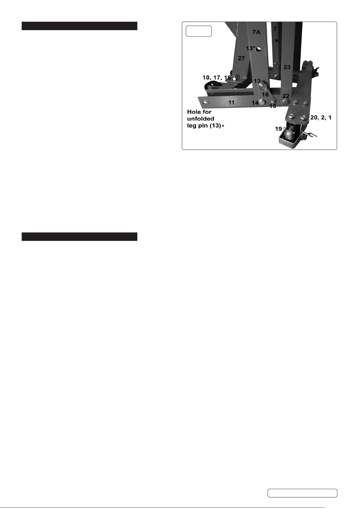
4. ASSEMBLY
Refer to attached parts list and g.1.
WARNING! It takes two people to build the crane. Leave all nuts loose until assembly is complete.
NOTE: Refer to attached parts diagram. Unpack and check against parts lists.
4.1. Attach castor wheels: fronts (parts 1-6), rears: (19) with screw (20), washer (2,) nut (1).
4.2. Fix legs (7 & 7A) into frame base (11) with bolt (14).
4.3. Fit connector plate brackets (16) to frame base (11) using screws (15).
4.4. Insert locating pin (13) into frame base (11).
4.5. Connect main column (27) to frame base (11).
4.6. Fixbottomofsupportstraps(23)ontoframebase(11),usebolt(22),washer(17)nut(18).Nextxtopofsupportstraps(23),use
bolt (14) washer (17) nut (18).
4.7. Connectmainboom(35)tomaincolumn(27)withbolt(32)atwasher(25)andnut(33).
4.8. Fixhydraulicram(28)tomaincolumn(27)withbolt(24)atwasher(25)andnut(26).
4.9. Fix hook (40) to extension boom (37), use bolt (38) washer (17) and nyloc nut (39).
4.10. Fit extension boom (27) into main boom (35) secure with locating pin (36) and hitch pin (12).
4.11. Fit rear handle (30) onto main column (27) with screw (15) and spring washer (2).
4.12. Tightenallxingsandcheckthecrane’sstabilitybeforeuse.
4.13. Bleed hydraulic system: Place the pump handle into the pump socket, ensure the release handle is in the open position and
pump the handle 10-15 times, through the full stroke, thus bleeding from the hydraulic system any air which may have entered the
system during transit.
4.14. How to store: Removelocatingpin(13)andliftlegstovertical.Retlocatingpin(13)throughthetopholeoftheconnectorplate
bracket (16) secure with hitch pin (12). OPERATION
4.15. OPERATION (Refer to Section 6.2 (a) regarding inspection before each and every use).
a) Ensure hand wheel is in the raise (fully clockwise position).
b) Place handle into pump socket and pump, the jib will raise. Continue to pump until the jib reaches the height at which the load can be secured.
c) Connect the crane hook to the load using a suitable certified sling or support beam. Ensure you are aware of the load weight,
and check that it is within the capacity of the crane (at the jib extension you are using) and the sling or support beam.
When removing engines ensure you know the weight to be lifted. Use only the lifting points recommended by the vehicle
manufacturer.
d) Lift only from directly above the load. WARNING! DO NOT LIFT THE LOAD AT AN ANGLE!
e) To lower load, turn release hand wheel VERY SLOWLY anti-clockwise avoiding any sudden movement.
WARNING! DO NOT allow the load to drop suddenly.
f) The crane is not a transportation device but may be used to reposition the load being worked on. To do so, lower load and jib
with care, to the lowest possible point before attempting to move. DO NOT try to move crane in a sideways direction. The crane is
not designed to support the load indefinitely. When you have repositioned the load, lower the load onto a secure and
appropriate working base, being fully aware of your own and other persons locations in relation to the lowering load.
g) When load has been secured, remove lifting sling, support beam etc. and place crane in a safe location with lifting beam fully lowered.
Original Language Version
© Jack Sealey Limited PH10.V6 Issue:1 22/03/21
g.1

5. MAINTENANCE/INSPECTION
NOTE: The crane MUST be kept clean and dry and must be maintained in accordance with these instructions.
5.1. LUBRICATION
a) Oil all working parts monthly.
b) The ram is filled with oil and should only require occasional topping up. For the occasional top up DO NOT use brake fluid, as this will
damage the hydraulic seals. Proceed as follows:
1) Use only good quality hydraulic jack oil available from your Sealey stockist.
2) DO NOT OVERFILL as this will cause failure.
3) After filling with hydraulic oil, pump the crane up to its full height and pour off any excess oil.
5.2. INSPECTION AND EXAMINATION OF CRANE BEFORE USE.
a) Before each use of the crane, perform an inspection for leaks, damage, loose or missing parts.
b) The workshop crane must be examined immediately if it has been subject to an abnormal load or shock. It is recommended that
such an examination is made by an authorised service agent.
c) The owner and/or operator must be aware that repair of this equipment will require specialised knowledge and facilities. It is
recommended that an annual examination of the workshop crane is made by an authorised service agent.
d) Unauthorised parts may be dangerous and will invalidate the warranty.
5.3. DEFINITION OF ‘INSPECTION’ AND ‘EXAMINATION’ BELOW.
INSPECTION:
Inspect the crane for defects and check the operation of controls, limiting and indicating devices without loading the crane. This check
does not normally require any part of the crane to be dismantled other than removal or opening of covers or housings.
EXAMINATION:
Verification that the crane can safely continue in service including a functional test of all safety devices i.e. limiting, indicating equipment,
brakes, clutches, safety valves etc to verify that they operate within the required tolerances. An examination is more thorough than an
inspection.
5.4. DAMAGED CRANES
Any crane which appears to be damaged, badly worn, or operates abnormally MUST BE REMOVED FROM SERVICE! It is
recommended that necessary repairs be made by an authorised service agent.
Sealey Group, Kempson Way, Suffolk Business Park, Bury St Edmunds, Suffolk. IP32 7AR
01284 757500 01284 703534 sales@sealey.co.uk www.sealey.co.uk
ENVIRONMENT PROTECTION
Recycle unwanted materials instead of disposing of them as waste. All tools, accessories and packaging should be sorted, taken to
a recycling centre and disposed of in a manner which is compatible with the environment. When the product becomes completely
unserviceable and requires disposal, drain any fluids (if applicable) into approved containers and dispose of the product and fluids
according to local regulations.
Note: It is our policy to continually improve products and as such we reserve the right to alter data, specifications and component parts without prior
notice. Please note that other versions of this product are available. If you require documentation for alternative versions, please email or call
our technical team on technical@sealey.co.uk or 01284 757505.
Important: No Liability is accepted for incorrect use of this product.
Warranty: Guarantee is 12 months from purchase date, proof of which is required for any claim.
Original Language Version
© Jack Sealey Limited PH10.V6 Issue:1 22/03/21
Table of contents
Other Sealey Construction Equipment manuals

Sealey
Sealey DF600.V2 User manual

Sealey
Sealey PH20 User manual

Sealey
Sealey SC10 User manual

Sealey
Sealey PH10.V4 User manual

Sealey
Sealey SC10.V4 User manual

Sealey
Sealey FDT3.V2 User manual

Sealey
Sealey PH5 User manual

Sealey
Sealey PBS90 User manual

Sealey
Sealey 500KCA User manual

Sealey
Sealey PBB04.V2 User manual

Sealey
Sealey PH10.V5 User manual

Sealey
Sealey PCB32 User manual

Sealey
Sealey PBS90.V2 User manual

Sealey
Sealey WF10Q User manual

Sealey
Sealey PFC101 User manual

Sealey
Sealey SG2000W User manual

Sealey
Sealey WD302.V2 Firmware update

Sealey
Sealey PH20.V4 User manual

Sealey
Sealey Quality MACHINERY WD302 User manual

Sealey
Sealey PCB32 User manual