Sealey PCM2500SP.V2 User manual

Thank you for purchasing a Sealey product. Manufactured to a high standard this product will, if used according to these instructions and properly
maintained, give you years of trouble free performance.
1. SAFETY INSTRUCTIONS
INSTRUCTIONS FOR:
PETROL PRESSURE WASHER
MODEL No:PCM2500SP.V2
IMPORTANT: PLEASE READ THESE INSTRUCTIONS CAREFULLY. NOTE THE SAFE OPERATIONAL REQUIREMENTS, WARNINGS & CAUTIONS.
USE THE PRODUCT CORRECTLY AND WITH CARE FOR THE PURPOSE FOR WHICH IT IS INTENDED. FAILURE TO DO SO MAY CAUSE
DAMAGE AND/OR PERSONAL INJURY AND WILL INVALIDATE THE WARRANTY. PLEASE KEEP INSTRUCTIONS SAFE FOR FUTURE USE.
GENERAL SAFETY
WARNING! RISK OF FLUID INJECTION. This washer operates at fluid pressures and velocities high enough to penetrate human
and animal flesh. If there is an occurrence of fluid injection seek medical help immediately.
WARNING! Stop the engine and disconnect the mains water supply before changing accessories or performing any maintenance.
WARNING! DO NOT operate the washer if damaged. Replace or repair using recommended parts only. Unauthorised parts may
be dangerous and will invalidate your warranty. Use authorised Service agent only.
Keep the washer in good condition. Regular maintenance will give the best and safest performance.
Ensure you comply with the water supply company regulations before connecting to the mains. If you are connecting to the mains drinking
water supply ensure you have a back flow preventer valve installed.
The water supply hose must be reinforced and have an internal diameter of 13mm (1/2”). The minimum water supply rate must be at least
equal to the cleaner capacity. The water temperers must not exceed 60oC, and the pressure must not exceed 10bar.
WARNING! DO NOT operate the washer without the water supply connected. To do so will damage the machine.
Position the washer as near as possible to the water supply.
Only use recommended washing detergents. Failure to do so may cause corrosion to equipment and hoses.
WARNING! Use the washer on a flat, level surface, in a horizontal position. Failure to do so will invalidate your warranty.
Wear safety goggles and adequate protective clothing, and anti-slip rubber soled footwear.
WARNING! The high pressure jet must be used with caution. Ensure you aim the lance correctly at the work surface. Failure to do so may
scatter loose particles at the same force as the water pressure, resulting in possible damage or personal injury.
Keep all persons and animals at a safe distance from the hose working area. It is difficult to give an exact safe distance as it will depend upon your
circumstances. We recommend at least 15 metres. Also ensure other persons are aware before you start to depress the washer trigger.
Hold the gun firmly with both hands as it will tend to “kick” backwards when you first pull the trigger.
DO NOT allow children or untrained persons to operate the washer.
DO NOT connect other appliances to the washer inlet or outlet. Only use the supplied or recommended outlet nozzle.
DO NOT use the washer if the water supply hose is damaged. Also check that the hose is laid out straight and safely.
DO NOT jam the operating trigger in the operating position and DO NOT pull the trigger without holding and aiming the gun correctly.
WARNING! DO NOT attempt to alter the pressure regulating valve as this may cause serious damage.
DO NOT move the washer by pulling on the high pressure hose or the mains water supply hose. Use the machine handle.
DO NOT direct jet against yourself, other persons or animals, electrical equipment or the machine itself.
WARNING! DO NOT leave the engine running for more than 2 minutes without operating the trigger, as temperature/pressure increase
may damage the sealing system.
DO NOT use the washer if you are tired or under the influence of alcohol, drugs or intoxicating medication.
Ensure that the hose pressure is discharged before disconnecting the mains water hose.
When not in use, disconnect from the water supply. Clean and dry the washer and store in a safe, dry, childproof area.
DO NOT allow the machine to become frozen.
ENGINE SAFETY
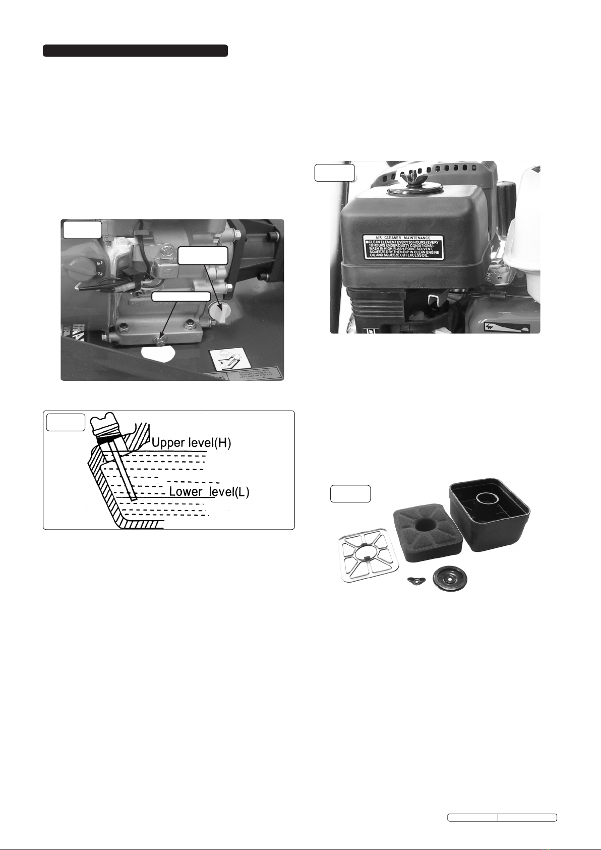
WARNING! Check the engine oil level before each startup. Only use a specified oil and never operate the engine with insufficient oil.
DO NOT operate the washer in an enclosed area as the motor exhaust fumes are a health hazard.
DO NOT use the washer with flammable, toxic or corrosive liquids.
DO NOT leave the washer unattended whilst operating and DO NOT remove the fuel cap whilst the engine is running.
DO NOT refuel the engine whilst it is running. Stop the engine and allow it to cool for two minutes before attempting to refuel.
DO NOT refuel in a closed or poorly ventilated environment as there is a danger of explosion or fire. Refuel out doors.
DO NOT smoke or place the washer near any naked flames whilst re-fuelling.
DO NOT operate washer if there is a fuel leak. Move the unit and avoid any combustion until the leak has been fixed and the machine is dry.
DO NOT start the engine if there are any flammable materials near the exhaust system or in the path of the exhaust gases.
DO NOT block the engine ventilation grilles.
Ensure engine fuel is stored in an approved container.
For long term storage ensure the fuel is drained and that the washer is adequately protected against frost.
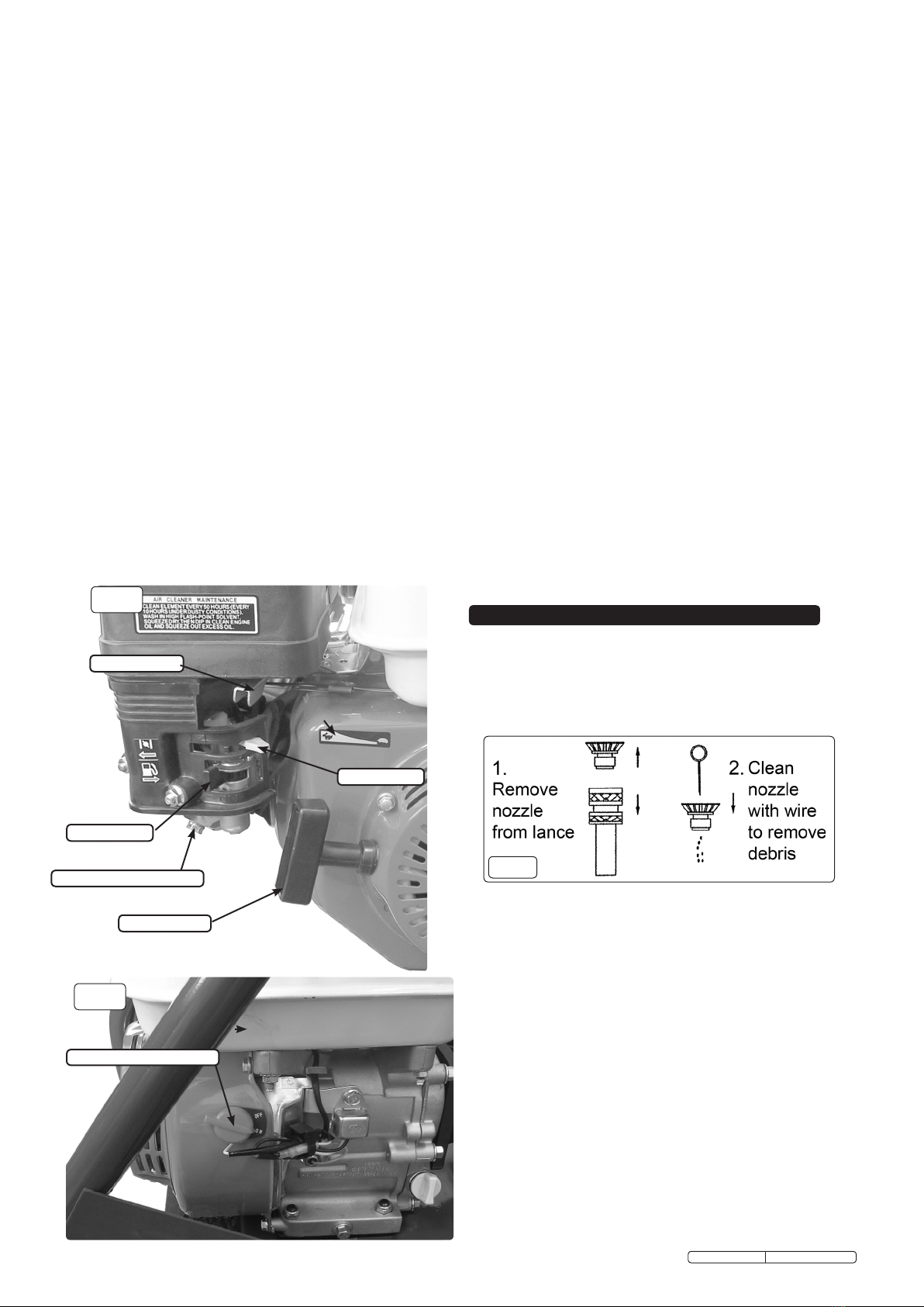
DO NOT operate the engine with either the silencer or air filter removed.
DO NOT touch the engine during or after use. To avoid burns allow it to cool before handling.
WARNING: The warnings, cautions and instructions discussed in this manual cannot cover all possible conditions and situations that may
occur. It must be understood that common sense and caution are factors which cannot be built into this product, but must be applied by
the operator
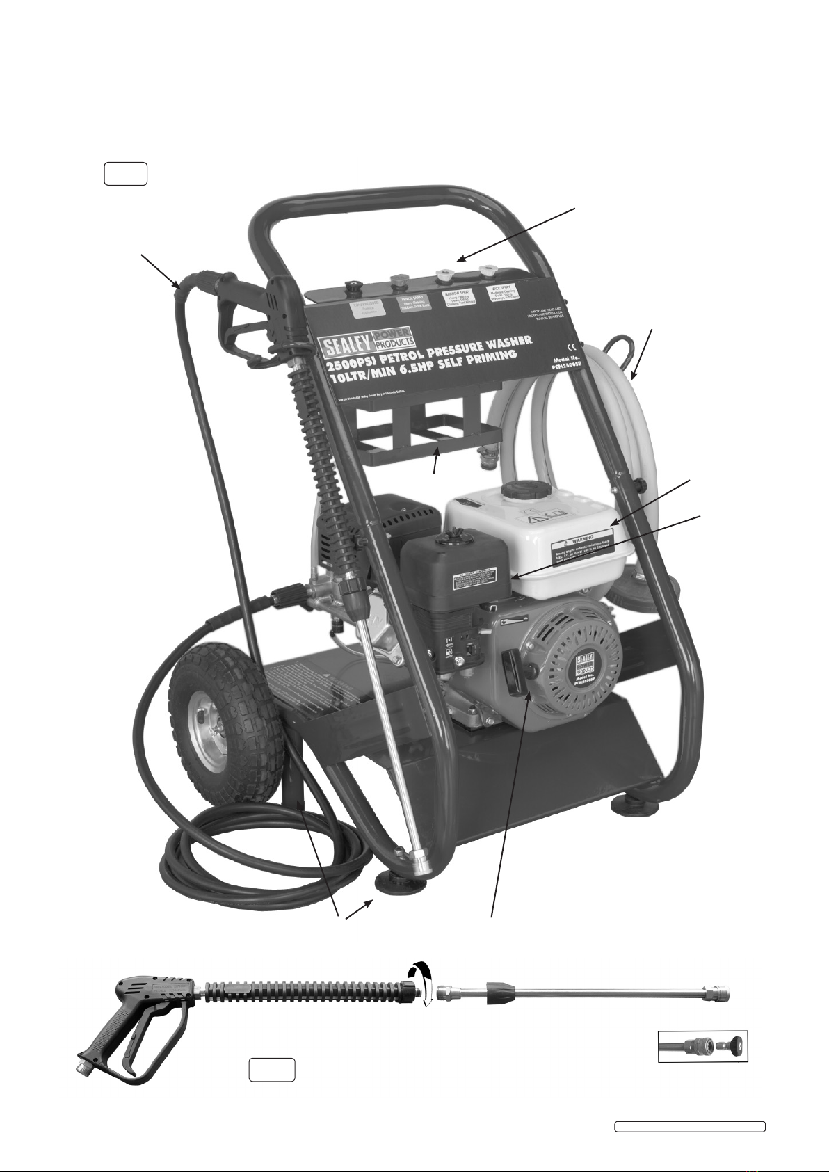
2. SPECIFICATION & INTRODUCTION
Output Pressure/Flow:....................... 2500psi/600ltr/hr
Hose Length: .......................................5.0mtr
Nozzles:....Low Pressure, Wide Angle, High Pressure, 0°, 15°, 40°
Maximum Inlet Temperature:............................60°C
Engine Type: ...................4 Stroke, single cylinder, Petrol
Engine Capacity: ....................................196cc
Engine Power ......................4.8kW(6.5hp) @ 3600rpm
Starting: ...........................................Recoil
Weight: ............................................46kg
FuelTank:......................................... .3.6ltr
Fuel:. . . ....................Unleaded Petrol 85 RON minimum
Fuel Consumption: . . . . . . . . . . . . . . . . . . . . . . . . . . . . .2.1 - 2.6ltr/hr
EngineOil: ...................................SAE10W-30
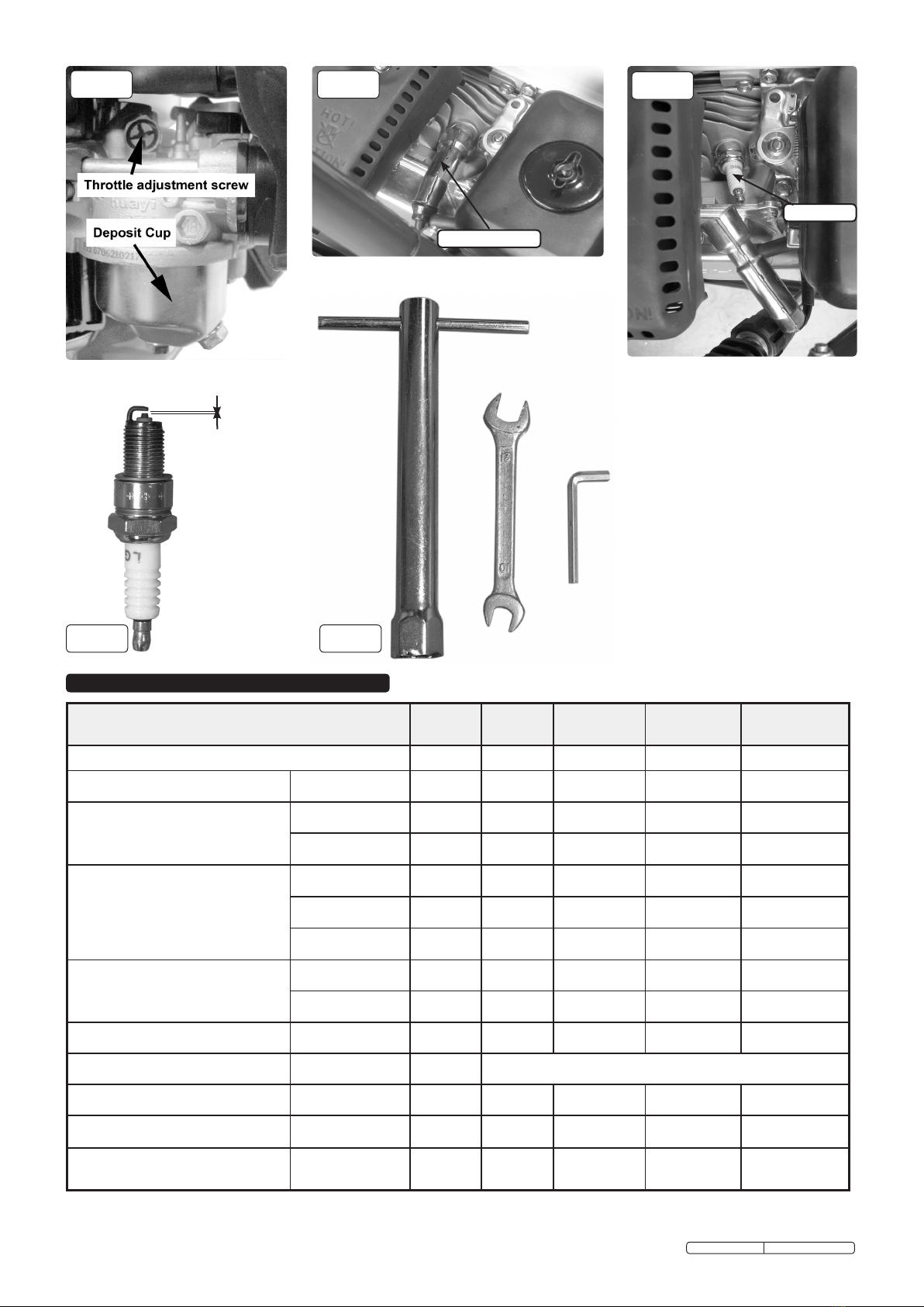
Spark Plug: .........................NGK BP6ES or BPR6ES
SparkPlugGap: ...............................0.7-0.8mm
Idle Speed:. .................................1700 +/- 15rpm
Valve Clearance (cold engine): Inlet .............0.15 +/- 0.02mm
................................................: Exhaust ..........0.20 +/- 0.02mm
Original Language Version PCM2500SP.V2 Issue: 1 - 27/01/12

fig.2
Petrol powered pressure washer with recoil starting. Ideal for commercial applications: with 5mtr pressure hose, 1mtr gun and lance and
adjustable nozzle. Self priming pump makes this unit fully portable and can be used where no mains pressure is available. Can draw clean
water from water butts and tanks etc. Low-pressure liquid detergent injection system with provision for detergent bottle stowage. Safety latch on
trigger and automatic low-oil engine shutdown reduce risks of misuse and equipment damage. Unit stands on four legs, two with sucker feet to
prevent creep, and tilts back onto two pneumatic tyred wheels for moving. Supplied with tools and full Instructions.
fig.1
Nozzle Holder
Fuel Tank
Air Filter
High Pressure Hose & Lance
Siphon Hose & Filter
Detergent Holder
Legs Recoil Starter
Original Language Version PCM2500SP.V2 Issue: 1 - 27/01/12

4.1 THERMAL RELIEF VALVE.
4.1.1 A thermal relief valve is fitted to protect the machine from
overheating if the gun remains closed for an extended
period of time or if the nozzle becomes blocked. To prolong the
life of the washer every effort should be made to avoid
overheating. It is recommended that if the unit is not going to
be used for two minutes or more it should be switched off.
4.2 TRIGGER LOCK.
4.2.1 To prevent accidental starting of the pressure washer the
trigger can be locked as shown in fig.4 by hinging out the
lever built into the back of the trigger and pressing it until it
locks into position. To release the locking lever flex the trigger
handle forwards and flip the lever out and fold it back into the
trigger. The trigger should be locked whenever the washer is
not in use.
4.3 LOW OIL SHUTDOWN.
4.3.1 The engine on this washer is equipped with a low oil shutdown
feature which stops the engine if the oil drops below a
specified level. Should the engine cut out, first check that it is
standing on a level surface. If the oil level is still low top it up
as described in Section 7.2.
Regulator Valve
Detergent Siphon
High Pressure Pipe
Mains / Siphon Pipe Water Inlet Connection
3. ASSEMBLY / PRE-OPERATION
Unpack contents and check to ensure all parts are in good
condition. If you experience any problems contact your
dealer immediately.
3.1 ASSEMBLY. (See fig.1.)
3.1.1 Screw together the two halves of the lance as shown in fig.2.
3.1.2 Select an appropriate nozzle from the nozzle stowage area. Pull
back the spring loaded sleeve at the end of the lance and insert the
nozzle. Let go of the sleeve and check that the nozzle is firmly
gripped in the fitting. The nozzle selection is colour coded and offers
the following options.
BLACK Low pressure wide angle spray for use with detergent.
RED High pressure, 0° degree spray, Very Aggressive. Use
with extreme caution to prevent damage to the surface
being cleaned or injury to persons or animals.
YELLOW High pressure, 15° Spray angle, normal cleaning,
provides a wide coverage and powerful water stream.
WHITE High pressure, 40° Spray angle, normal cleaning and
rinsing, provides a less powerful stream of water and is
suitable for most general cleaning jobs.
3.1.3 To attach the high pressure hose to the water inlet on the gun,
push it into the inlet on the gun until it is fully seated and tighten
as shown in figs.4 & 5.
3.1.4 Attach the other end of the high pressure hose to the pump
outlet as shown in fig.6. Push the end of the hose into the
pump outlet until it is fully seated and then tighten to secure.
3.1.5 Connect either a mains water supply hose or the siphon hose
to the pump inlet as shown in fig.6. USE COLD WATER ONLY.
Note: The water supply hose must be reinforced and have an internal
diameter of 13mm (1/2”). The minimum water supply rate must
be at least equal to the washer flow rate.
The siphon pipe may require priming if drawing water from a
level lower than the pump.
3.2 DETERGENT DELIVERY.
3.2.1 Attach the BLACK low pressure nozzle to the end of the lance.
Remove the cap from a bottle of detergent and place the bottle
in the detergent holder.
3.2.2 On the top of the pump outlet is a brass siphon injection fitting.
Push the detergent input pipe onto the fitting (fig.6) and place the
filter on the other end into the container of detergent ensuring
that it goes all the way to the bottom. When used with the low
pressure black nozzle detergent will be drawn from the
container by siphonic action and will mix automatically with the
water from the pump. Use Sealey General Purpose Detergent,
AK130 (25ltr) or AK131 (5ltr). Traffic Film Remover is also
available, AK132 (25ltr) or AK133 (5ltr).
3.3 ENGINE LUBRICATION.
3.3.1 THE PRESSURE WASHER ENGINE IS SHIPPED FROM THE
FACTORY WITHOUT OIL. DO NOT ATTEMPT TO START THE
ENGINE BEFORE THE SUMP HAS BEEN FILLED WITH THE
CORRECT AMOUNT OF OIL. Refer to the section 7.2.
3.4 FUEL.
3.4.1 Fill the tank with fresh unleaded petrol fuel. Keep fuel level
below the fuel filter which sits in the neck of the tank.
3.5 PUMP.
3.5.1 The pump is supplied already filled with oil. Re-check the oil
level before using the unit. The combined oil filler cap and
dipstick is on top of the pump. The oil level can also be seen in
the sight glass on the end of the pump.
3.6 SITING OF UNIT.
3.6.1 Ideally the unit should be used on level ground. Where this is
not possible the unit should not be inclined more than 20° in
any one direction.
3.7 RUNNING IN THE ENGINE.
3.7.1 For the first 20 hours of operation the unit should not be placed
under heavy load. After the first 20 hours change the oil.
fig.3
fig.4
fig.6
fig.5
4. SAFETY FEATURES
BLACK RED YELLOW WHITE
5. OPERATION
WARNING! THE PRESSURE WASHER ENGINE IS SHIPPED
FROM THE FACTORY WITHOUT OIL.
WARNING! RISK OF FLUID INJECTION. This washer
operates at fluid pressures and velocities high enough to
penetrate human and animal flesh. If there is an occurrence
of fluid injection seek medical help immediately.
WARNING! Ensure you read, understand and apply
Section 1 safety instructions.
WARNING! Dry running can seriously damage the unit.
WARNING! DO NOT leave motor running for more than
2 minutes without operating the trigger, as
temperature/pressure increase may damage sealing system.
Original Language Version PCM2500SP.V2 Issue: 1 - 27/01/12

6. MAINTENANCE (WASHER)
6.2 Check and clean the water inlet filter every 50 operating
hours. The filter is moulded into a rubber washer. Unscrew
the brass connector from the black fitting on the water inlet on
the pump. Push the black fitting backwards which will eject
the filter/washer and then clean the filter washer. If the filter is
damaged in any way it should be replaced.
6.3 Check and clean the detergent filter at the end of the
detergent input tube on a regular basis.
6.4 WINTER STORAGE: Fill the pump with an antifreeze
mixture before storing in a frost free, safe, dry area for the
winter. Introduce the antifreeze by the following method.
6.4.1 Shut off the water supply and disconnect the supply hose.
Relieve pressure within the pump by squeezing the gun
trigger. Remove the high pressure hose and let all water drain
from it. Hold gun/lance with nozzle downwards and pull
trigger until all water has drained out.
6.4.2 Connect a short length of garden hose to the water inlet and
using a funnel pour an antifreeze mixture into it.
6.4.3 Pull the recoil starter several times to circulate the antifreeze
through the pump. Continue to add antifreeze and pull the
recoil until antifreeze is expelled from the pump.
5.1. MANUAL STARTING PROCEDURE.
5.1.1 Check engine oil level before each use.
5.1.2 Check that the mains water feed hose is laid straight, and
then fully open the water tap. Check to ensure there are no
leaks from hoses or connections.
5.1.3 Release gun trigger safety catch and depress trigger to allow
any air left in the system to escape, hold until there is a steady
flow of water coming out and release the trigger.
5.1.4 Rotate the engine switch clockwise to the ON position. See fig.8.
5.1.5 Fig.7 shows the fuel tap in the OFF position. Push the
fuel tap up to the right to the open position.
5.1.6 If the engine is cold move the choke lever to the left to close
the choke.
5.1.7 Move the throttle lever slightly to the left, fig.7 shows the
throttle in the full throttle position.
5.1.8 Turn the engine switch to the ON position.
5.1.9 Take hold of the recoil starter handle (see fig.1) and pull it
slowly until you feel resistance, then let it return slowly.
5.1.10 Now pull the starting handle hard and fast all the way out. Use
two hands if necessary.
5.1.11 If the engine doesn’t start repeat the process from 5.1.9.
5.1.12 Once started adjust throttle valve to the required setting and
return the choke to the open position when the engine is warm.
5.2. CLEANING
5.2.1. Only apply detergent using the BLACK low pressure nozzle.
5.2.2. Depress the trigger to apply the detergent to the dry surface
which is to be cleaned.
Vertical surfaces should be cleaned from the bottom upwards.
5.2.3 When detergent application is complete remove the syphon
tube from the detergent container and place it in a container
of clean water. Run the washer at low pressure to purge the
gun of detergent.
5.2.4. Leave the detergent to act for 1-2 minutes, but DO NOT
allow the surface to dry.
fig.7
fig.8
fig.9
5.2.5. The detergent should be rinsed off using either the YELLOW
or WHITE high pressure nozzles depending on the
spray angle required. Do not use the RED nozzle as the
aggressive spray action may erode the surface being
cleaned. Always lock the gun trigger before changing nozzles.
5.2.6. Hold the gun firmly with both hands and commence washing
with high pressure clean water. When rinsing work from the
top to the bottom to avoid streaks.
Note: Care should be taken when selecting the nozzle for the job in
hand. The distance from the nozzle to the surface being
cleaned will depend on the condition of that surface. Always
start further away and slowly move closer until the level of
cleaning required is achieved.
5.3. SHUT DOWN PROCEDURE.
5.3.1 When cleaning has finished and the unit is no longer
required allow the engine to run unloaded for 2 minutes
before shutting down.
5.3.2 Stop the engine by pushing the throttle lever fully to the right.
(See fig.7) and turn the engine switch to the OFF position.
5.3.3 Turn off the fuel tap. (See fig.7)
5.3.4 Turn off the mains water supply.
5.3.5 Discharge residual pressure from the washer by pressing the
trigger until no more water comes out of the nozzle.
5.3.6 Engage the gun trigger safety catch.
5.3.7 In an emergency turn the engine switch to the OFF position.
CAUTION!
a) Avoid sudden bursts of water as this will cause the
water pressure to drop and put extreme pressure on the
hoses and connections.
b) If another person is using water from the same supply as
the washer, the water pressure will drop and the washer
will not operate correctly. Switch the engine off
immediately and wait until the pressure is restored.
Maintenance should only be performed with the engine turned
off and the unit disconnected from the mains water supply.
6.1 CLEANING THE NOZZLES: Pull back the brass sleeve on
the end of the lance and pull out the nozzle. Clean the nozzle
with wire provided (fig 9). If this does not improve the flow
from the nozzle it should be replaced.
Throttle Lever
Fuel Tap
Choke
Carburettor Drain plug
Recoil Starter
Engine ON / OFF Switch
Original Language Version PCM2500SP.V2 Issue: 1 - 27/01/12

7. MAINTENANCE (ENGINE)
7.1 Change engine oil after the first 20 hours of operation.
Thereafter, change oil every six months or every 100 hours of
operation. Change oil more often if engine is operated under
heavy load, or in high ambient air temperatures. During
normal operation, partially burned fuel, small particles of
metal from the cylinder walls, pistons, bearings and
combustion deposits will gradually contaminate the oil. If the
oil is not changed regularly, these foreign particles can cause
increased friction and a grinding action which shortens the life
of the engine. Fresh oil also assists in cooling. Old oil
gradually becomes thick and loses its cooling ability as well
as its lubricating qualities.
fig.10
fig.11
7.2 CHECKING THE OIL LEVEL. Ensure the unit is on a level
surface.
7.2.1 Unscrew the dipstick/oil filler cap (see fig.10) and wipe it
clean of oil. Note that the maximum oil level should be just
below the opening of the filler neck.
7.2.2 Check the oil level by seating the dipstick into the hole
without screwing it in. See fig.11 above. On removal the oil
level should be between the two marks on the dipstick. If it is
at the lowest level or below, top-up immediately with an
SAE10W30 oil.
7.2.3 Screw dipstick fully home to seal oil fill hole.
Note: The engine is fitted with a low oil sensor which will
automatically shut the engine down in a low oil situation. The
sensor may also operate if the unit is not on a level surface.
7.3 CHANGING THE OIL.
7.3.1 Change the oil. Operate the engine for 3 minutes to warm the
oil then stop the engine using the shut down procedure
described in section 5.3. There is a hole in the chassis below
the oil drain plug. See fig.10. Place a suitable container below
the hole, remove the plug and allow the oil to drain. Replace
the drain plug and refill with fresh oil. Check the oil level using
the dipstick. Dispose of the old oil according to local authority
guidelines.
7.4 FUEL FILTER: The fuel filter is in the neck of the fuel tank.
7.4.1 Clean it every 300 hours.
7.6 AIR FILTER. To access the air filter element unscrew and
remove the wing nut and seal washer on the top of the cover.
Lift the air filter off its threaded mounting rod
7.6.1 Remove the metal retainer and the foam filter from the inside of
the outer air filter casing.
7.6.2 Wash the foam element with a household detergent or a high
flash-point solvent and squeeze dry. When the element is
thoroughly dry soak it in clean engine oil. Squeeze out any
excess oil, fit back into the outer casing and replace the metal
retainer.
7.6.3 Place the air filter back over the threaded rod and secure with
the seal and wing nut.
7.6.4 The foam element should be replaced after every 300 hours of
service.
fig.12
fig.13
7.5 ENGINE STORAGE. If the unit is not to be used for more
than one month the following procedure should be followed.
7.5.1 Drain the fuel from the fuel tank, fuel line and fuel tap.
7.5.2 Ensure that the engine switch is in the off position and pull the
recoil starter handle slowly until an increase in pressure is felt
indicating that the piston has commenced its compression
stroke and leave it in this position. This closes both the intake
and exhaust valves and prevents the inside of the cylinder from
rusting.
7.5.3 Cover the unit and store it in a clean dry place that is well
ventilated and away from open flame or sparks.
Oil Drain Plug
Dipstick
and Oil Filler
7.7 CARBURETTOR. To adjust the idling speed, turn the throttle
adjustingscrew(g.14)clockwisetoincreaseand
anti-clockwise to decrease engine speed.
Standard idling speed:1700 +/- 15rpm
7.7.1 Tocleanthedepositcup(g.14),setthefueltaptoOFF,undo
the central bolt and lower the deposit cup, take care not to spill
any fuel, dispose of old fuel in accordance with local authority
guidelines.Washcomponentsinanon-ammableorhigh
ashpointcleaningsolvents,drycomponentsandret
components in reverse order. Turn fuel tap back ON and check
for leaks.
7.8 SPARK PLUG. To remove the spark plug, pull off the spark
pluglead(g.15)andremovethesparkplug(g.16)usingthe
sparkplugwrenchsupplied(g.18).
Note: Care must be taken if the engine is hot due to the close proximity
of the exhaust silencer to the spark plug.
7.8.1 Clean spark plug using a wire brush and check the insulator for
damage, replace if damaged or at service schedule.
7.8.2 Checktheelectrodeclearance(g.17)withafeelergauge,
adjust if required using a plug gap tool.
7.8.3 Replacesparkplugandretpluglead.
Original Language Version PCM2500SP.V2 Issue: 1 - 27/01/12

8. ENGINE MAINTENANCE SCHEDULE
Spark Plug Lead
Spark Plug
fig.14 fig.15 fig.16
fig.18fig.17
0.7 - 0.8mm
Operation Hours Daily
First Month
or 20hrs
Every 3 months
or 50hrs
Every 6 months
or 100 hrs
Every 12 months
or 300hrs
Task
Check and tighten nuts and bolts Check
Engine oil
Oil Level Check
Replace
Replace air cleaner element
Check
Clean
Replace
Spark Plug
Clean / Adjust
Replace
Fuel Tank & Fuel Filter Clean
Fuel Supply Line Check Every 2 years (replace if required)
Carburettor Deposit Cup Clean
Idling Check / Adjust
Intake and exhaust valve clearances Check / Adjust
Original Language Version PCM2500SP.V2 Issue: 1 - 27/01/12

9. GENERAL TROUBLESHOOTING
PROBLEM POSSIBLE CAUSES REMEDY
Engine will not start Low oil sensor has shut down engine Top up oil level
Engine Switch not in the ON position Turn switch ON
Pressure build up in pump Operate trigger
Engine is overloaded Nozzle partially blocked Clean nozzle
Excessive pressure build up ReturntoSealeydealertohavereuxvalveadjusted
Engine running, but pump not
building maximum pressure or
has irregular pressure
Mainswaterturnedofforinsufcientsupply Turn on mains water or increase supply
Unit has been stored in freezing temperatures Thaw out completely including hose, gun and wand
Waterinletlterclogged Cleanoutlter
Kink in water supply hose Straighten out hose
Lance nozzle worn or damaged Replace nozzle
Air in pump Refer to section 5.1 - 5.1.3 and bleed air out of system
No intake of detergent Injection tube not properly attached to unit Pushtubermlyontosiphonnozzle
Tube cracked or split Replace tubing
Highpressurenozzletted Fit low pressure nozzle (BLACK)
Siphon nozzle blocked Clean nozzle
Trigger will not move Trigger lock engaged Release trigger lock
Noisy operation Worn bearings Return to Sealey dealer for bearing replacement
Tappet clearances excessive Return to Sealey dealer for servicing.
Cavitation in pump Check inlet hose for correct size or leaks
Rough / pulsating operation
with pressure drop
Inlet restriction Check inlet hose for correct size, blockages or leaks
Cavitation in pump Check inlet hose for correct size or leaks
Engine running hot Wrong grade of oil Use recommended oil
Oil too high / low Adjust oil level to recommended level
NOTE: It is our policy to continually improve products and as such we reserve the right to alter data, specifications and component parts without prior notice.
IMPORTANT: No liability is accepted for incorrect use of this product.
WARRANTY: Guarantee is 12 months from purchase date, proof of which will be required for any claim.
INFORMATION: For a copy of our latest catalogue and promotions call us on 01284 757525 and leave your full name and address, including postcode.
01284 757500
01284 703534
sales@sealey.co.uk
Sole UK Distributor, Sealey Group,
Kempson Way, Suffolk Business Park,
Bury St. Edmunds, Suffolk,
IP32 7AR
www.sealey.co.uk
Web
email
Original Language Version PCM2500SP.V2 Issue: 1 - 27/01/12
Table of contents
Other Sealey Pressure Washer manuals

Sealey
Sealey PC2275 User manual

Sealey
Sealey PWM2500SP.V2 User manual

Sealey
Sealey PW2512 User manual

Sealey
Sealey PC2301 User manual

Sealey
Sealey PC3451 User manual

Sealey
Sealey PC1950 User manual

Sealey
Sealey PC2901 User manual

Sealey
Sealey PCM2500.V2 User manual

Sealey
Sealey PCM2500SP User manual

Sealey
Sealey PW2000HW User manual

Sealey
Sealey PC3401.V2 User manual

Sealey
Sealey PW1850 User manual

Sealey
Sealey PW2500HW User manual

Sealey
Sealey PW1610 User manual

Sealey
Sealey PW2400 User manual

Sealey
Sealey PC3150 User manual

Sealey
Sealey PW1860 User manual

Sealey
Sealey PW1601 User manual

Sealey
Sealey PW2012R User manual

Sealey
Sealey PC2100 User manual