Sealey PWH616 User manual

WELDING HELMET WITH POWERED AIR
PURIFYING RESPIRATOR (PAPR)
MODEL NO: PWH616
Thank you for purchasing a Sealey product. Manufactured to a high standard, this product will, if used according to these
instructions, and properly maintained, give you years of trouble free performance.
IMPORTANT: PLEASE READ THESE INSTRUCTIONS CAREFULLY. NOTE THE SAFE OPERATIONAL REQUIREMENTS, WARNINGS & CAUTIONS. USE
THE PRODUCT CORRECTLY AND WITH CARE FOR THE PURPOSE FOR WHICH IT IS INTENDED. FAILURE TO DO SO MAY CAUSE DAMAGE AND/OR
PERSONAL INJURY AND WILL INVALIDATE THE WARRANTY. KEEP THESE INSTRUCTIONS SAFE FOR FUTURE USE.
1. SAFETY
1.1. ELECTRICAL SAFETY
WARNING! It is the user’s responsibility to check the following:
Check all electrical equipment and appliances to ensure that they are safe before using. Inspect power supply leads, plugs and
all electrical connections for wear and damage. Sealey recommend that an RCD (Residual Current Device) is used with all electrical
products. You may obtain an RCD by contacting your local Sealey stockist.
If the product is used in the course of business duties, it must be maintained in a safe condition and routinely PAT (Portable
Appliance Test) tested.
Electrical safety information, it is important that the following information is read and understood.
1.1.1. Ensure that the insulation on all cables and on the appliance is safe before connecting it to the power supply.
1.1.2. Regularly inspect power supply cables and plugs for wear or damage and check all connections to ensure that they are secure.
1.1.3. Important: Ensure that the voltage rating on the appliance suits the power supply to be used and that the plug is tted with the
correct fuse - see fuse rating in these instructions.
8DO NOT pull or carry the appliance by the power cable.
8DO NOT pull the plug from the socket by the cable. Remove the plug from the socket by maintaining a rm grip on the plug.
8DO NOT use worn or damaged cables, plugs or connectors. Ensure that any faulty item is repaired or replaced immediately by a
qualied electrician.
1.1.4. This product is tted with a BS1363/A 13 Amp 3 pin plug.
If the cable or plug is damaged during use, switch the electricity supply and remove from use.
Replace a damaged plug with a BS1363/A 13 Amp 3 pin plug. If in doubt contact a qualied electrician.
Class II products are wired with live (brown) and neutral (blue) only are marked with the
Class II symbol;
A) Connect the BROWN live wire to the live terminal ‘L’.
B) Connect the BLUE neutral wire to the neutral terminal ‘N’.
C) After wiring, check that there are no bare wires and ensure that all wires have been correctly connected.
Ensure that the cable outer sheath extends inside the cable restraint and that the restraint is tight.
DO NOT connect either wire to the earth terminal.
Sealey recommend that repairs are carried out by a qualied electrician.
1.2. GENERAL SAFETY
WARNING! This helmet is not suitable for use with laser welding or CUTTING or for overhead welding applications.
9Ensure all workshop safety rules, regulations and conditions are complied with when using welding equipment. The helmet will not
oer protection against misuse of workshop tools, equipment, or accessories.
9Maintain the helmet in good condition and protect cartridge from liquid and dirt contact. Regularly replace the protective lens and
replace any damaged or worn parts. Use genuine parts only. Unauthorised parts may be dangerous and will invalidate the warranty.
9Ensure the front cover window is securely in place before use.
9Fit the helmet and adjust the head band so the helmet will sit as low and near to your face as possible.
9 Use helmet only in temperatures ranging from -5°C to 55°C.
9 Remove ill tting clothing, remove ties, watches, rings and other loose jewellery.
9Maintain correct balance and footing.
9 Ensure the oor is clear from obstructions, not slippery and wear non-slip protective shoes.
9Keep children and unauthorised persons away from the working area.
WARNING! The helmet will only protect the eyes and face from radiation and sparks. It will not protect against explosive devices or
corrosive liquids.
8DO NOT use helmet for any purpose for which it is not designed.
8DO NOT use helmet unless you have been instructed in its use by a qualied person.
8DO NOT open or tamper with the shade cartridge.
8DO NOT get the helmet wet or use in damp or wet locations.
8DO NOT leave work place with helmet in lowered position, as bright light source may darken cartridge unexpectedly.
Recommended fuse rating:
3 A
Original Language Version
© Jack Sealey Limited
Charger
Indoor use only
PWH616 Issue 1 04/12/20
Refer to
instructions

Original Language Version
© Jack Sealey Limited PWH616 Issue 1 04/12/20
8DO NOT place the helmet on a hot surface.
8DO NOT use helmet without front cover window tted. To do so will invalidate your warranty.
9 Clean helmet (see section 5.5) and store the helmet in a safe, dry, childproof location.
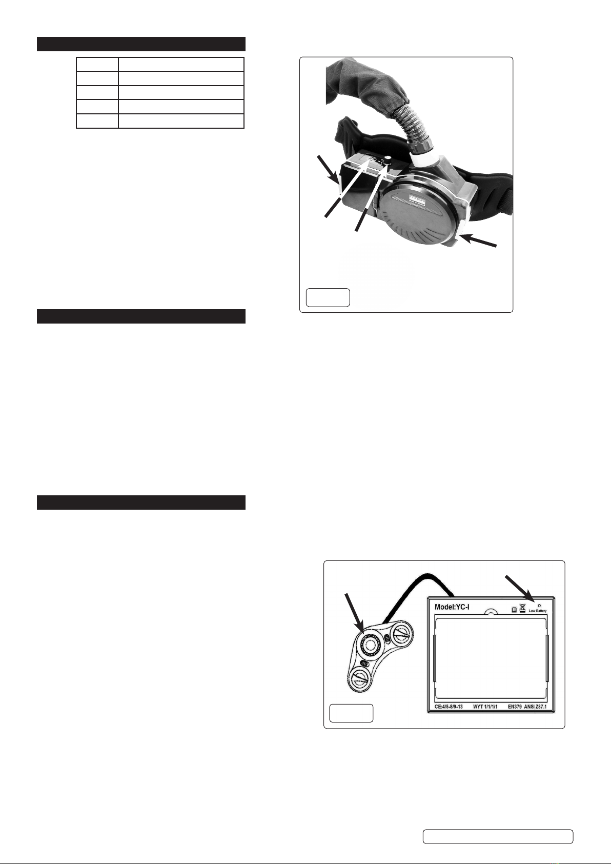
WARNING! Before welding always inspect the cartridge lter to ensure that it is not damaged. To test the lter prior to welding, direct
the front of the cartridge lter to a bright light source which will cause the lens to darken. Then using your hand rapidly cover and
uncover the sensor. The lter should lighten momentarily then return to a dark state.
WARNING! DO NOT use the helmet if damaged or you suspect it may be faulty. (Contact Sealey Stockist).
▲DANGER! DO NOT use if, at any time, the face plate in the cartridge FAILS to darken when exposed to a welding spark. Remove
cartridge and return to your Sealey stockist for checking.
9 Continued use of the product knowing that the auto darkening feature is NOT FUNCTIONING may DAMAGE YOUR EYES and
CAUSE BLINDNESS.
▲DANGER! DO NOT wear this respirator system to enter areas where:
1. Atmospheres are oxygen decient.
2. Contaminant concentrations are unknown.
3. Contaminant concentrations are Immediately Dangerous to Life or Health.
4. Contaminant concentrations exceed the maximum use concentration determined using the assigned Protection Factor for the
specic respirator system.
WARNING! The Particle lter cannot be cleaned. DO NOT attempt to remove contamination using for example compressed air as
this will destroy the lters, the equipment will not give the expected protection and the warranty will be invalidated.
9If ventilation is poor, wear an approved air-supplied respirator.
9Read and understand the Material Safety Data Sheets and the manufacturer’s instructions for metals, consumables, coatings,
cleaners, and degreasers.
9 Work in conned space only if it is well ventilated, or while wearing an air-supplied respirator. Always have a trained watch-
person nearby. Welding fumes and gases can displace air and lower the oxygen level causing injury or death. Be sure the breathing
air is safe.
8DO NOT weld in locations near degreasing, cleaning, or spraying operations. The heat and rays of the arc can react with vapours to
form highly toxic and irritating gases.
8DO NOT weld on coated metals, such as galvanized, lead, or cadmium plated steel, unless the coating is removed from the weld
area, the area is well ventilated, and while wearing an air-supplied respirator. The coatings and any metals containing these
elements can give o toxic fumes if welded. RESPIRATOR (PAPR) MISUSE can be hazardous. Welding produces fumes and gases.
Breathing these fumes and gases can be hazardous to your health.
9Read and follow these instructions and the safety labels carefully. The powered air purifying respirator (PAPR) helps protect the
user from specic airborne contaminants but must be used correctly to be fully eective. Have an industrial hygienist test the air
in your facility to ensure the PAPR provides adequate protection from contaminants in your environment. If you have questions
about the respirator, see equipment warning label and consult your Safety Director and a certied Industrial Hygienist.
9 Follow all applicable EN/ANSI/CSA/AS&NZS, and other regulatory guidelines pertaining to the use of respirators.
8DO NOT use the powered air purifying respirator where there is danger of re or explosion.
8DO NOT use the powered air purifying respirator in windy conditions or negative pressure inside the hood may draw in
contaminants from the outside air.
8DO NOT use the powered air purifying respirator without a properly installed spark guard cover. Without the spark guard cover,
welding sparks may ignite the lter, or damage the lter and allow unltered air into the helmet.
9 The powered air purifying respirator does not supply oxygen. Use the respirator only in atmospheres for which it is EN/ANSI/CSA/
AS&NZS approved. DO NOT use the respirator where oxygen levels are 19.5% or lower, where contaminant levels are unknown or
are immediately dangerous to life or health, or where the contaminant levels exceed the respirator specications.
8DO NOT enter a hazardous area until you are sure the respirator equipment is correctly assembled, working properly, and properly
worn.
9 Before each use, inspect the respirator equipment for damage and verify it operates properly, Before using the respirator, test air
ow to verify it is providing an adequate volume of air.
8DO NOT use the powered air purifying respirator without all lter components or with the blower turned o, as hazardous levels of
oxygen and carbon dioxide may accumulate in helmet.
9Always wear the powered air purifying respirator when entering a contaminated area. DO NOT remove the respirator until outside
the contaminated area.
9Dangerous contaminants may not smell or be visible. Leave the area immediately if you notice the following:
- Breathing becomes dicult.
- You experience dizziness, impaired vision, or eye, nose, or mouth irritation.
- The powered air purifying respirator alarm sounds.
- The equipment is damaged.
- Air ow decreases or stops.
- If you think the equipment is not supplying adequate protection.
8DO NOT remove the equipment until you are in a safe area.
8DO NOT repair, modify, or disassemble the powered air purifying respirator or use with parts or accessories not supplied by the
manufacturer. Use only those components that are part of the approved assembly.
9 Replace damaged or clogged lters. DO NOT wash or reuse lters. DO NOT clean lters by tapping or with compressed air or lter
elements may be damaged. Dispose of used lter elements according to local, state, and federal requirements.
9 The powered air purifying respirator must be used with the helmet, hood, and lters recommended by the manufacturer to provide a
respirator system. See the label on the blower for information on the required equipment.
8DO NOT use the powered air purifying respirator belt or shoulder straps(if equipped) as a safety harness.
2. INTRODUCTION
PAPR (Powered Air Purifying Respirator) system with auto darkening welding helmet. Lithium battery powered respirator unit provides the user
a constant ltered stream of air to their head and face for up to approx. 8 hours. The lter is designed to reduce or remove dust and particles but
not vapours and gases. The kit meets performance class TH1 according to EN 12941:1998/A2:2008. Adjustable airow settings of 150/180/210L/

Original Language Version
© Jack Sealey Limited
min. Features an audible alarm to alert user of low battery/low airow. Inner hood has protective clear visor to BS EN166 standards. Welding
helmet has adjustable shade control from 9-13 & 5-8. Fully automatic switching from light to dark on striking arc @ 1/25,000s. Solar panel
power supply to welding helmet. Contoured design helmet with adjustable headband for added comfort. Suitable for MIG, TIG and ARC welding.
Complies with BS EN379, EN175, EN166, EN12941 and DIN standards.
3. SPECIFICATION
Model No:...................................................................................................... PWH616
HELMET:
Shade Active:.................................................................................5-8 & 9-13 Variable
Shade Inactive: .......................................................................................................... 4
Grinding Function:.................................................................................................. Yes
Viewing Area: ..............................................................................................98 x 62mm
Operating Time Light / Dark: .........................................................................1/25,000s
Operating Temperature: ......................................................................... -5°C to +55°C
POWERED AIR PURIFYING RESPIRATOR:
PAPR Air Flow Settings:...................................................................150/180/210L/min
PAPR Lithium Battery Charging Time:..................................................... 2.5hr approx.
PAPR Filter Classication: ........................................................................ TH1 P R SL
PAPR REPLACEMENT PARTS:
Filter cartridge:............................................................................................PWH616.F
Lithium battery: ........................................................................................ PWH616.BP
Blower hose: ............................................................................................ PWH616.BH
HELMET REPLACEMENT PARTS:
Block nut .................................................................................................PWH616.H01
Front Cover Lens ....................................................................................PWH616.H02
Auto-Darkening Filter Cartridge ..............................................................PWH616.H03
Headband ...............................................................................................PWH616.H04
Sweat Band.............................................................................................PWH616.H05
4. HELMET
4.1. HELMETADJUSTMENT(g.1)
4.1.1. To adjust the t-to-head, use the handwheel (g.1.1) on the back of the strap to increase or decrease the head band circumference.
4.1.2. Further adjustment for t-to-head can be achieved by increasing or decreasing the length of webbing straps g.1.2 and g.1.3.
4.1.3. To adjust the distance between the user’s face and the front of the mask, loosen the side thumbwheels and depress the spring loaded
pin on the hinge points (g.1.4, g.1.5). Slide the helmet to the desired position and release the pin. There are three locations into
which the spring loaded pin may be seated. Re-tighten the thumbwheels. This should be done one side at a time and both sides
should be located at the same position for proper auto-darkening lter operation.
4.1.4. To adjust the viewing angle loosen the side thumbwheels. Depress the tab on item g.1.6 to disengage it from the rotation lock
(g.1.7) and set the angle to suit. There are several locations on the rotation lock into which the tab may be engaged. Re-tighten the
thumbwheels.
1
2
3
5
4
6
7
PWH616 Issue 1 04/12/20
g.1

Original Language Version
© Jack Sealey Limited
4.2. SHADE GUIDE TABLE
4.3. CONTROLS(g.2)
4.4. SHADE VALUE
4.4.1. The shade value ranges are divided into two sections ( 5-8 or 9-13). The shade range can be set to either 5 - 8 or 9 - 13 using the
selector switch (g.2.1).
4.4.2. The shade value can be set using the control dial (g.2.2). Check the shade guide table (above) to determine the proper shade
number for your application. The shade goes darker from 5 to 8 or from 9 to13.
4.5. SENSITIVITY CONTROL
4.5.1. The sensitivity can be set from LOW to HIGH by using the sensitivity contgrol dial (g.2.5). The LOW setting suits excess ambient light
or with another welding machine close by. The HIGH setting suits low amperage welding and welding in areas with low light conditions,
especially low amperage argon arc welding. Selections between LOW and HIGH are suitable for most of indoor and outdoor welding
operations.
4.6. DELAY CONTROL
4.6.1. When welding ceases, the viewing window automatically changes from dark back to light but with a pre-set delay to compensate.
The delay time can be set from MIN (0.2 sec) to MAX (1.0 sec), by shade delay control (g.2.4). The minimum delay suits spot or short
welds. The maximum delay suits heavy current welding and reduces eye fatigue from the arc. Selections between MIN and MAX are
suitable for most of indoor and outdoor welding operations.
4.7. GRINDING
4.7.1. To select between grinding and welding, set the Grind/Weld select switch (g.2.3) to “GRIND”.
NOTE: It is important to return this switch to the WELD position when the grinding operation is completed.
PWH616 Issue 1 04/12/20
4
3
2
1
5
g.2
Item Description
1 Shade grades select switch
2 Shade knob
3Grind / Weld select switch
4 Delay knob
5Sensitivity knob

5. RESPIRATOR
5.1. BATTERY
5.1.1. To remove battery, unclip the latch (g.3.1) and lift out
the battery.
ALLOW THE BATTERY TO COOL BEFORE CHARGING
5.2. FILTER
5.2.1. To remove the lter, unclip the latch (g.3.2) and lift out
the lter.
5.3. CONTROLS
5.3.1. Turn the unit on or o using the button (g.3.3).
5.3.2. To set the air volume delivered, use the control
dial (g.3.4.)
NOTE: When the battery charge level is low, the unit will beep
twice quickly repeatedly. Leave the area immediately.
NOTE: If the lter or air ow is compromised, the unit will beep
once repeatedly. Leave the area immediately.
6. OPERATION
6.1. CHECKING THE UNIT BEFORE USE
Before using the respirator, check the following items:
9Face seal; Inspect the face seal and replace if damaged.
9 Check front cover lens for scratches / damage and replace if necessary.
9 Correct and comfortable tting for user.
9 Air Filter Assembly; Verify the air lter is suitable for the application. Also be sure the lter is undamaged, and securely located.
9 Breathing Tube; Be sure the tube is undamaged and properly connected to the blower assembly and hood.
9 Battery; Ensure the battery is fully charged and securely connected within the blower assembly. The charger shows a red LED when
charging which turns to green when the battery is fully charged. A fully charged battery can work for up to 6 hours.
9 Air Flow Alarm; Turn on blower assembly and check for audible alarms indicating poor/restricted air ow.
9 Hood; Inspect the hood and replace if damaged.
6.2. HELMET SETTINGS
6.2.1. Set shade, sensitivity and delay options to suit operational and environmental conditions (See section 4).
NOTE: If the unit is used in a grinding role, ensure that the Grind / Weld select switch (g.2.3) is returned to the Weld option after use.
NOTE: If the helmet does not darken upon striking an arc, stop welding immediately and refer to the troubleshooting section.
7. MAINTENANCE
7.1. HELMET FRONT COVER LENS REPLACEMENT
7.1.1. Replace the front cover lens if it is damaged (cracked, scratched, pitted or dirty). Remove the old front cover lens by sliding screw
driver blade or similar into the relief under the lens at the bottom of the retaining frame and pull the lens out. and replace with new
lens. Remove any protective lm before installing the new one.
7.2. HELMET AUTO-DARKENING FILTER CARTRIDGE (FIG.4)
7.2.1. Carefully remove the head band and face mask from the helmet.
7.2.2. When the Low Battery light (g.4) is lit you will need to replace
the cartridges’ batteries. The batteries are housed in a covered
compartment on the inside face of the control panel accessed
from the inside of the helmet. Slide the battery compartment
cover o and replace the batteries.
7.2.3. To replace the inside cover lens if it is damaged (cracked,
scratched, pitted or dirty), slide a screw driver blade or similar
under the lens, ex it and remove from the unit.
7.3. REPLACING WELDING HELMET ADF FILTER CARTRIDGE
7.3.1. Remove the three control knobs and two slide controls by prising
them carefully from the unit.
7.3.2. From inside the helmet remove the ve cross head screws.
7.3.3. Unclip the holding frame from the helmet by pushing the two rear
clips away from the unit.
7.4. REPLACING PAPR FILTER CARTRDGE
7.4.1. Open the lter compartment (g.3.2) and remove the lter.
7.4.2. Handle soiled lter carefully and use suitable PPE i.e. gloves and face mask.
7.5. CLEANING AND DISINFECTING
7.5.1. Detach breathing tube and respirator. Inspect all parts for damage. Replace all damaged parts prior to storage or next use.
Clean the outer surfaces of PAPR assembly with a soft cloth dampened in a solution of water and mild, pH neutral detergent.
DO NOT immerse the respirator or any element in water.
DO NOT use solvents or abrasive cleaners. DO NOT attempt to clean the interior of the blower with compressed air or vacuum.
Ensure the electrical contacts of the blower and battery pack are dry.
Battery compartment
On rear
Low Battery light
g.4
2
1
3
4
g.3
Item Description
1Battery compartment
2 Filter compartment
3 On / O button
4Volume control
Original Language Version
© Jack Sealey Limited PWH616 Issue 1 04/12/20

Filter: Open the lter cover (g.3.2) and inspect the lter. Replace if excessively dirty.
7.6. STORAGE:
If the blower will not be used for an extended period, remove the lter and battery and store them in a clean, dry, cool place free of
solvent-based vapours.
8. TROUBLESHOOTING
8.1. WELDING SHIELD;
PROBLEM POSSIBLE CAUSES SUGGESTED SOLUTIONS
Dicult to see through lter Cover lens dirty Clean or replace cover lens
Filter lens dirty Clean lter lens
Filter does not darken when arc is struck Grind Mode Selected Adjust to ‘Weld’ mode.
Sensors or Solar Panel blocked Make sure sensors or solar panel are
exposed to weld arc without blocking
Set Sensitivity to LOW Adjust Sensitivity to required level
Low voltage of lithium batteries Replace with new lithium batteries if indicator
turns red
Filter darkens without arc Set Sensitivity to HIGH Adjust Sensitivity to required level
Filter remains dark after welding Set Delay to MAX Adjust Delay to required level
8.2. FILTER AND HOOD;
FAULT POSSIBLE SOLUTION
Blower does not supply air to hood 1. Press On switch to start blower
2. Recharge battery
3. Verify battery is properly connected to blower
4. Remove blockage from blower outlet and breathing tube
Battery pack’s charge lasts less than
expected
1. Ensure battery pack is fully charged
2. Replace battery
3. Replace charger
4. Check the air lter and replace it if necessary
Blower cannot be turned o Press ON/OFF button for one second
Battery red level light is ashing Charge or replace the battery
Danger light is on, alarm sounds or blower
vibrates
Check the blower air ow paths are clear.
Sealey Group, Kempson Way, Suffolk Business Park, Bury St Edmunds, Suffolk. IP32 7AR
01284 757500 01284 703534 sales@sealey.co.uk www.sealey.co.uk
ENVIRONMENT PROTECTION
Recycle unwanted materials instead of disposing of them as waste. All tools, accessories and packaging should be sorted, taken to
a recycling centre and disposed of in a manner which is compatible with the environment. When the product becomes completely
unserviceable and requires disposal, drain any fluids (if applicable) into approved containers and dispose of the product and fluids
according to local regulations.
WEEE REGULATIONS
Dispose of this product at the end of its working life in compliance with the EU Directive on Waste Electrical and Electronic Equipment
(WEEE). When the product is no longer required, it must be disposed of in an environmentally protective way. Contact your local solid
waste authority for recycling information.
Parts support is available for this product. Please email sales@sealey.co.uk or telephone 01284 757500
Original Language Version
© Jack Sealey Limited PWH616 Issue 1 04/12/20
Table of contents
Other Sealey Welding Accessories manuals

Sealey
Sealey PWH620.V2 User manual

Sealey
Sealey Siegen Tools S01000.V2 User manual

Sealey
Sealey SGA1.v3 User manual

Sealey
Sealey SGA3 User manual

Sealey
Sealey PWH399 User manual

Sealey
Sealey Siegen Tools S01001.V2 User manual

Sealey
Sealey SR20.V2 User manual

Sealey
Sealey PWH601 User manual

Sealey
Sealey PWH610 User manual

Sealey
Sealey VSAC135 User manual

Sealey
Sealey MIG/N315 User manual

Sealey
Sealey MIG/LITE User manual

Sealey
Sealey SGA1.V4 User manual

Sealey
Sealey PWH599 User manual

Sealey
Sealey WFS94X User manual

Sealey
Sealey PWH620 User manual

Sealey
Sealey SGA3.V2 User manual

Sealey
Sealey SHADE 10 User manual

Sealey
Sealey GCSC219 User manual

Sealey
Sealey SSP6 User manual