Sealey PWH399 User manual

Thank you for purchasing a Sealey Power Product. Manufactured to a high standard this product will, if used according to these
instructions and properly maintained, give you years of trouble free performance.
IMPORTANT: PLEASE READ THESE INSTRUCTIONS CAREFULLY. NOTE THE SAFE OPERATIONAL
REQUIREMENTS, WARNINGS AND CAUTIONS. USE THIS PRODUCT CORRECTLY AND WITH CARE FOR THE
PURPOSE FOR WHICH IT IS INTENDED. FAILURE TO DO SO MAY CAUSE DAMAGE OR PERSONAL INJURY
AND WILL INVALIDATE THE WARRANTY. PLEASE KEEP INSTRUCTIONS SAFE FOR FUTURE USE.
INSTRUCTIONS FOR:
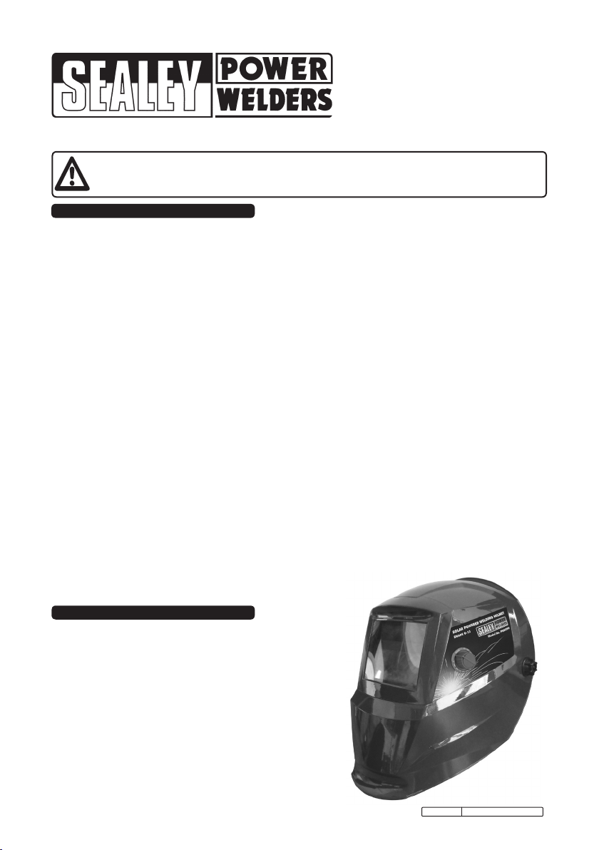
WELDING HELMET SOLAR
POWERED SHADE 9 - 13
MODEL NO:
PWH399
1. SAFETY INSTRUCTIONS
WARNING! THIS HELMET IS NOT SUITABLE FOR USE WITH LASER WELDING OR CUTTING OR FOR OVERHEAD
WELDING APPLICATIONS.
3 Ensure all workshop safety rules, regulations and conditions are complied with when using welding equipment. The helmet
will not offer protection against misuse of workshop tools, equipment, or accessories.
3 Maintain the helmet in good condition and protect cartridge from liquid and dirt contact. Regularly replace the protective lens
and replace any damaged or worn parts. Use genuine parts only. Unauthorised parts may be dangerous and will invalidate
the warranty.
3 Ensure the front cover window is securely in place before use.
3 Fit the helmet and adjust the head band so the helmet will sit as low and near to your face as possible,
3 Use helmet only in temperatures ranging from -5°C to 55°C (23°F to 131°F).
3 Store helmet only in temperatures ranging from -20°C to 70°C (-4°F to 158°F).
3 Remove ill fitting clothing, remove ties, watches, rings and other loose jewellery.
3 Maintain correct balance and footing.
3 Ensure the floor is clear from obstructions, not slippery and wear non-slip shoes.
3 Keep children and unauthorised persons away from the working area.
WARNING! The helmet will only protect the eyes and face from radiation and sparks. It will not protect against explosive
devices or corrosive liquids.
7 DO NOT use helmet for any purpose for which it is not designed.
7 DO NOT use helmet unless you have been instructed in its use by a qualified person.
7 DO NOT open or tamper with the shade cartridge.
7 DO NOT get the helmet wet or use in damp or wet locations.
7 DO NOT leave work place with helmet in lowered position, as bright light source may darken cartridge unexpectedly.
7 DO NOT place the helmet on a hot surface.
7 DO NOT use helmet without front cover window fitted. To do so will invalidate your warranty.
3 Clean helmet (see section 5.5) and store the helmet in a safe, dry, childproof location.
WARNING! The materials of the helmet may, when coming into contact with the wearers skin, cause an allergic reaction to
susceptible individuals.
WARNING! Before welding always inspect the cartridge filter to ensure that it is not damaged. To test the filter prior to
welding, direct the front of the cartridge filter to a bright light source which will cause the lens to darken. Then using your
hand rapidly cover and uncover the sensor. The filter should lighten momentarily then return to a dark state.
WARNING! DO NOT use the helmet if damaged or you suspect it may be faulty. (Contact Sealey dealer).
DANGER! DO NOT USE if, at any time, the face plate in the cartridge FAILS to darken when exposed to a welding
spark. Remove cartridge and return to your Sealey dealer for checking.
Continued use of the product knowing that the auto darkening feature is NOT FUNCTIONING may DAMAGE YOUR
EYES and CAUSE BLINDNESS.
2. INTRODUCTION
High quality variable shade 9-13 welding helmet manufactured and
tested to BS EN 379 and BS EN 175. Fully automatic switching from light
to dark on striking arc. Fitted with solar power panel - no batteries
required. Features infinitely adjustable sensitivity and delay controls for
switching dark to light. Grinding mode enabling the user to grind without
the need to remove mask. Contoured design offers full face and neck
protection and also protects lens from scratching when unit is laid down.
Fitted with comfortable head band and non-slip quick release ratchet
mechanism. Suitable for MIG, TIG and arc welding.
Original Language Version PWH399 Issue No.1 03/06/10

4. INSTRUCTIONS FOR USE
WARNING! Before using the helmet for welding ensure you
have read and understood the safety instructions in Section 1.
4.1 Assemble the headband parts (see fig.1) into the mask as
indicated in fig.2. Before the mask can be used the
headband must be adjusted to fit the user properly.
4.2 ADJUSTING THE FIT OF THE HELMET.
The overall circumference of the headband can be made
larger or smaller by pushing in and rotating the knob on the
back of the headband (See adjustment ‘A’ in fig.2). This
can be done whilst wearing the helmet and allows just the
right tension to be set to keep the helmet firmly on the
head without it being too tight.
4.3 If the headband is riding too high or too low on your head
adjust the strap which passes over the top of your head. To
do this release the end of the band by pushing the locking
pip out of the hole in the band. Slide the two portions of the
band to a greater or lesser width as required and push the
locking pip through the nearest hole (See adjustment ‘B’ in
fig.2).
4.4 Test the fit of the headband by lifting up and closing down
the helmet a few times whilst wearing it. If the headband
moves whilst tilting re-adjust it until it is stable.
4.5 ADJUSTING HELMET TILT.
If the cartridge window is not aligned with the eyes when
the helmet is in the lowered position adjust the tilt of the
helmet in relation to the headband. Referring to fig.2 loosen
the knob ‘C’ adjacent to the tilt plate ‘D’. Lift the tilt plate off
the fixed peg within the helmet and rotate it to the required
position and allow one of the holes in the plate to drop back
over the peg. Retighten the clamp knob ‘C’.
4.6 SELECTING SHADE LEVEL
4.6.1 Refer to the shade guide in Section 7 and adjust the knob
on the side of the helmet to the correct setting (fig.3).
4.7 GRIND POSITION. Turn the shade knob (fig.3)
anti-clockwise until it clicks into the grind position. When
grinding is finished the knob must be turned back to the
appropriate shade position before welding again. Failure to
do this could result in damage to your eyes.
4.8 SELECTING DELAY TIME/RESPONSE TIME
4.8.1 The delay time in which it takes the lens to change from
dark to light or vice versa can be varied from 0.1sec to 0.9
sec, this adjustment is carried out by turning the delay time
knob on the inside of the cartridge, see fig.4.
4.9 SENSITIVITY
4.9.1 For normal ambient light conditions set the sensitivity knob
to the high setting (fig.4).
4.9.2 For conditions where there is an excess of light, which may
affect the performance of the lens, turn the knob to the low
setting.
fig.3
fig.4
3. SPECIFICATION
Original Language Version PWH399 Issue No.1 03/06/10
fig.1
fig.2
Model No:......................................................... PWH399
Shade Active: .................................................... 9 - 13 Variable
Shade Inactive:.................................................. 4
Viewing Area: .................................................... 96 x 42mm
UV/IR Protection:............................................... YES
Operating time, Light/Dark: ............................... 0.0001ms
Temperature Range:.......................................... -5°C to +55°C
Power: ............................................................... Solar Cells

5.1 CHANGING THE SHADE CARTRIDGE.
All components clip into the front of the helmet as shown
in fig.5 above.
5.1.1 To access the cartridge firstly remove the front cover ‘A’
by releasing the four clips accessible on the inside of the
helmet above and below the cartridge.
5.1.2 Release the top clips first (see ‘A’ in fig.4) by pressing
them downwards and forwards. Then release the bottom
clips (see ‘B’ in fig.4) by pressing them upwards and
forwards. Lift off the front cover.
5.1.3 Pull the grey knob off the potentiometer shaft on the side
of the helmet. Unscrew the nut at the base of the shaft
and remove it. Push the shaft through into the inside of
the helmet so that the potentiometer is hanging free on
its lead.
5.1.4 Referring to fig.5, push downwards on the two clips ‘H’
whilst pushing the bottom edge of the cartridge outwards
from inside the helmet. When it is free from the lower
clips pull the cartridge downwards and forwards to free it
from the upper retainers. See ‘G’ in fig.5.
5.2 FITTING NEW CARTRIDGE.
Take the new shade cartridge and hook the top edge
under the upper retainers ‘G’ ensuring that the
potentiometer has passed into the inside of the helmet.
Push firmly on the bottom edge of the cartridge so that it
snaps into place behind the two clips ‘H’.
5.2.1 Refix the potentiometer to the side of the helmet and
turn the shaft anticlockwise until it clicks into the ‘off’
position. Push the knob back onto the shaft so that the
pointer points to the ‘Grind’ position.
5.2.2 Place the front cover ‘A’ onto the front of the helmet so
that the cover clips pass into the matching holes in the
helmet. Press firmly on the top of the cover to engage
the top clips then press firmly at the base of the cover
to engage the lower clips.
5.3 REPLACING OUTER PROTECTIVE WINDOW.
Remove the front cover ‘A’ as described in sections
5.1.1 and 5.1.2.
5.3.1 Remove the window ‘B’ from the back of the front cover
by lifting one vertical edge and sliding the whole window
sideways until it releases from its retaining points. The
window will flex sufficiently to allow you to do this.
5.3.2 Flex the new window and slide it in from one side under
the retaining points until it is in position. Ensure that it
laps over the inside of the window opening on either
side.
5.4 REPLACING CARTRIDGE PROTECTIVE WINDOW.
The protective cartridge window that can be seen on the
inside of the helmet should be replaced if damaged. The
window is held in place at its four corners.
5.4.1 To remove the window place your finger tip into the
scoop just below the cartridge controls (see fig.4 ) and
flex the window upwards until the upper corners release.
Lift out the window.
5.4.2 Take the new window and place one vertical edge under
the corner retainers in the window recess. Flex the
window in the middle and tuck the other end into the
corner retainers.
5.5 CLEANING.
Clean helmet by wiping with a soft cloth. Clean cartridge
surfaces regularly. Do not use solvent based cleaners .
Clean sensors and solar cells with methylated spirit using
a clean cloth and wipe dry with a lint-free cloth.
5. MAINTENANCE
Original Language Version PWH399 Issue No.1 03/06/10
fig.5

NOTE: It is our policy to continually improve products and as such we reserve the right to alter data, specifications and component parts without prior notice.
IMPORTANT: No liability is accepted for incorrect use of this equipment.
WARRANTY: Guarantee is 12 months from purchase date, proof of which will be required for any claim.
INFORMATION: Call us for a copy of our latest catalogue on 01284 757525 and leave your full name and address including your postcode.
01284 757500
01284 703534 sales@sealey.co.uk
www.sealey.co.uk
Web
Sole UK Distributor
Sealey Group,
Bury St. Edmunds, Suffolk.
7. SHADE GUIDE & MARKINGS
Original Language Version PWH399 Issue No.1 03/06/10
Problem Cause Solution
Irregular darkening or
dimming.
The headband may have been unevenly set on the two
sides of the helmet (unequal distances from the eyes to
the shade cartridge).
Readjust the distance of the
shade cartridge.
Shade cartridge does
not darken or ickers.
The sensors are soiled or obstructed. Clean.
Front cover lens oiled or damaged. Clean or replace.
Welding current too low. Adjust weld amps.
Poor vision. Operative lenses and/or shade cartridge soiled. Check, clean or replace.
Insufcient background lighting. Adjust light.
Slow response. Operating temperature too low. Do not use at temperatures
below -10oC (14oF).
Welding helmet slips. Headband adjustments incorrect. Refer to section 4.
6. PROBLEM SOLVING
CURRENT (AMPERES)
WELDING
PROCESS
0.5 2.5 10 20 40 60 125 175 225 275 350 450
1.0 5.0 15 30 50 100 150 200 250 300 400 500
Covered
Electrode
Shade 9 S10 Shade 11 Shade 12 Shade 13 S14
MIG Plate
Welding
Shade 10 Shade 11 Shade 12 Shade 13 S14
MIG Sheet
Welding
Shade 10 Shade 11 Shade 12 S13 S14 S15
TIG Shade 9 S10 Shade 11 S12 Shade 13 Shade 14
MAG Shade 10 S11 S12 Shade 13 S14 S15
Arc Gouging Shade 10 S11 S12 S13 S14 S15
Plasma Cutting Shade 11 Shade 12 Shade 13
Plasma Welding 4 5 6 7 8 9 10 11 S12 Shade 13 Shade 14 S15
Meaning of the markings on the filter:
4 9 13 SEALEY 1 3 1 379
Light state
scale no.
Lightest dark
state scale
no.
Darkest
state scale
no.
Manufacturers
identification.
Optical class. Diffusion of
light class.
Variation in
luminence
transmittance
class.
Number of
the applied
standard.

EC DECLARATION
OF CONFORMITY
We the sole importers into the UK, hereby declare that the equipment described below
Description and Function:...............................................................................................................................................
Model/Type:.....................................................................................................................................................................
Manufacturing Date / Serial number (optional).................................................................................................................
Manufacturer's authorised representative within the EC: Jack Sealey Ltd. Kempson Way, Suffolk Business Park,
Bury St. Edmunds, Suffolk, IP32 7AR
Conforms to the requirements of the following Directives, as indicated.
2006/42/EC Machinery Directive 2000/14/EC Outdoor Noise Emissions Directive
2006/95/EC Low Voltage Directive 2002/96/EC WEEE Directive
2004/108/EC EMC Directive 2002/95/EC RoHS Directive
93/68/EEC CE Marking Directive 97/23/EC Pressure Equipment Directive
And the following harmonised standard(s):…………………………………………………..................................................
……………………………………………………………………………………………….......................................................
National technical standards and specifications (if applicable):………………………………............................................
……………………………………………………………………………………………….......................................................
Technical file compiled by: Jack Sealey Ltd.
Signed:……………………………………..
Date:………………………………............. Place: Bury St.Edmunds.
Name:…………………………………………
Position:…………………………………....
Being the responsible person appointed by the manufacturer.
Welding Helmet Solar Powered Shade 9-13
PWH399
BS EN 175: 1997 BS EN 379: 2003 + A1: 2009
BS EN 165: 2005 BS EN 166: 2002
10-May-2010
Steve Buckle
Marketing Director
Table of contents
Other Sealey Welding Accessories manuals

Sealey
Sealey SHADE 10 User manual

Sealey
Sealey VSAC135 User manual

Sealey
Sealey WFS94X User manual

Sealey
Sealey SGA1.V4 User manual

Sealey
Sealey SWH189 User manual

Sealey
Sealey PWH599 User manual

Sealey
Sealey Siegen Tools S01000.V2 User manual

Sealey
Sealey PWH620 User manual

Sealey
Sealey SGA3.V2 User manual

Sealey
Sealey PWH620.V2 User manual

Sealey
Sealey SGA3 User manual

Sealey
Sealey PWH601 User manual

Sealey
Sealey MIG/LITE User manual

Sealey
Sealey PWH616 User manual

Sealey
Sealey GCSC219 User manual

Sealey
Sealey PWH599 User manual

Sealey
Sealey SR20.V2 User manual

Sealey
Sealey SGA1.v3 User manual

Sealey
Sealey PWH599 User manual

Sealey
Sealey Siegen Tools S01001.V2 User manual