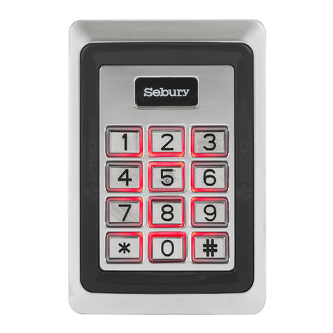
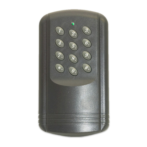
Sebury BC2019 User manual

Instruction ManualV1.0
1 Product overview
1.1 Product introduction
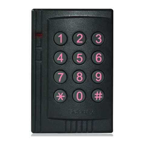
This product uses high-strength zinc alloy housing, Proximity card (EM card, also known as
ID card) or password to open the door, built-in highly integrated micro-controller, simple
circuit, safe and reliable, economical and durable, suitable for office, villa etc.
1.2 Product Features
> 1000 user cards bound with 1000 user passwords, and the user can modify password by himself
> Opening door modes: card, card + password, card or password, password.
> Opening time: 50mS, 1-98 seconds for normal mode, 99 seconds for switch mode;
> It can connect with the door magnetic detection for alarm or door closing prompts;
> Built-in high current MOS tube, can directly drive external alarm;
> Safe mode can be set: 10 times of invalid card or password will automatically lock the machine
for 10 minutes;
> Can connect with an exit button, convenient to open the door from inside.
> Safety screw at the bottom to prevent malicious destroy.
BC2019 Access control

1.3 Functional component
1.4 Technical parameters
> Working voltage: DC12±2V
> Static current: ≤20mA
> Operating current: ≤100mA
> Drive electric lock current: ≤3A
> Working environment temperature: -20~50°C
> Working environment humidity: 0~95% (no condensation)
> Maximum card reading distance:5cm
2 Installation, wiring and Debugging
2.1 Installation
Unscrew the anti-tamper screw on the bottom of the product with the special anti-tamper
screwdriver, remove the back case of the product, then according to the opening position of the
back case, use the impact drill to open the corresponding holes on the wall, make a hole with
diameter larger than 8mm, and four holes with diameter of 6mm, then insert four matching plastic
expansion screws, and fix the back case to the wall with four matching self-tapping screws.
As shown below:
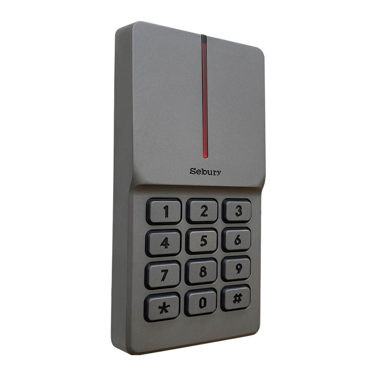
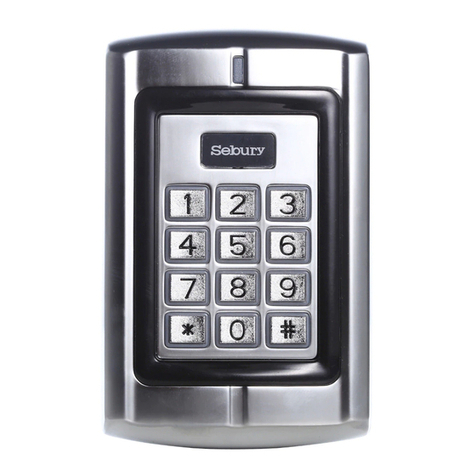
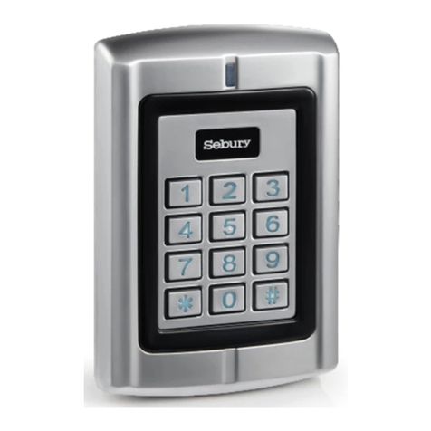
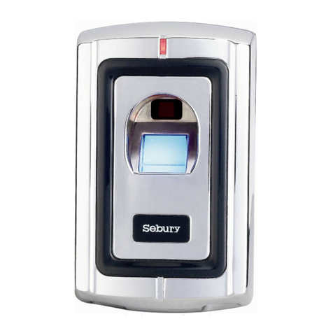
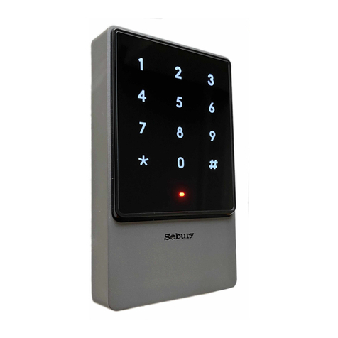
Button frame indicator
LOGO
Indicator light
Metal Key
Card reader antenna
Metal body

2.2Wiring
According to the selected wiring diagram, connect the wire according to the wiring diagram one
by one. The rest unused wire should be wrapped by the electrical tape. Be careful not to short
circuit, or the power supply will be burned out, then insert the wires into the access control keypad
8P socket. check every wire is correct, briefly turn on the power to see if the indicator LED light is
normal, and the buzzer will beep once, otherwise cut off the power supply immediately, Check the
wires again.
If everything is correct, install the front case of the product on the bottom case on the wall.
Remove the screws and fix them. As shown below:
The correspondence between the color of wire and their function:
Door Strike Relay NC
Door Strike Relay NO
Door Strike Relay Com
Alarm Switched negative when active
To Door EXIT Request Button Then Negative
To Door Contact Then To Negative
(+) 12VDC Positive Regulated Power Input
(-) Negative Regulated Power Input
3
2
1
NO
COM
NC
Blue
Purple
Orange
8
7
6
5
4
OPEN
D_IN
12V
ALARM
Yellow
Brown
Red
Black
Grey
GND
Exit button
Door detecting switch
-
+
Alarm
ALARM-
OPEN
D_IN
Grey
Yellow
Brown
Red
Black
Blue
Purple
Orange
+12V
GND
NC
COM
NO
NO COM NC +12V GN PUSH
Special Power Supply
Unlocking time
should be set
to the minimum
For strike lock: BC2019 opening time should set to be 50mS
For magnetic lock: BC2019 door opening time shoule set to be 5S
Electric control lock
-+
Electric Bolt lock
-+

2.3 Debug
Turn on the power supply and test according to the instructions. The debugging will be completed
until the lock can be opened correctly by reading card, password and exit button.
3 Basic functions
Operating conventions:
> A long sound"Di-"indicates correct operation. Three short sounds"Di Di Di"indicate wrong
operation . The indicator light flash in green means operate correctly.
> "#"indicate confirm completed, normally used behind pass word, ID number, or parameter.
> "*"indicate cancel the current operation or return to the previous menu.
> The management menu is fixed to 1 digit from 0-6, cannot press key"#"after it. After entering
setting menu, the indicator light turns to orange.
> Under administrator mode, it will automatically exit to standby state if there is no operation
within 30 seconds.
> Under non- administrator mode, it will automatically exit to standby state if there is no operation
within 5 seconds.
Light and buzzer indication:
3.1 Enter into administrator mode
* 6 digits administrator password #
888888 is the default factory administrator code. It fixed to 6 digits.
For example, press *888888* to enter into administrator mode.
Enter into the administrator mode first before start the below operations.
operation status Light color Buzzer
Standby Red
PIN inputting Red flash
Read the card in Card & PIN mode Red flash
Enter into administrator mode Red flash
Enter menu setting status Orange
Successful operation Green A long sound
Unlock the lock Green
Press numeric key A short sound
Press * A long sound
Failed operation Three short sound

3.2 Change the administrator password
Press 0 new password # new password #
For example, change administrator password to 999999, press 0 999999 # 999999#
3.3 Add card user
Below 3 methods to add a card user, the ID number range is 0-999, the user password is fixed to
6 digits, and it can be operated continuously. Press * to exit the add user menu.
3.3.1 Quickly to add card user
press 1 read card … *
For example, continuously add 3 cards. Press 1,read card, read card, read card *
3.3.2 Specifying the ID number to add a card
Press 1 ID number # read card … *
For example, continuously add 3 cards with ID numer as 1,2,3
Press 1 1#read card 2# read card 3#read card *
3.3.3 Specifying the ID number to add a user password
1 (ID number) # (6 digits user password) # ... *
For example, consecutively set 3 passwords with ID numbers 4, 5, and 6: 14#444444#5#555555#6
#666666#*.
3.4 Deleting users
There are three ways to delete a user, where the ID number ranges from 0 to 999, every ID
number corresponds to a card or password, and the deletion ID number indicates that a card or
a password is deleted, and the operation can be continued. Press the * key to exit the delete user
menu
3.4.1Quickly delete the card
2 swipe card ... *
Example, delete 3 cards continuously: 2, swipe card, swipe card, swipe card, *
3.4.2 Specify ID Number to Delete Card or Password
2 (ID number) # ... *
For example, continuously delete three users with ID numbers 1, 2, and 3: 2,1#2#3#*.
3.4.3 Deleting all users
2 0000 # *
3.5 Setting the door opening method
3 0 # Open the door by card.
3 1 # Open the door by card and password.
3 2 # Default value, open the door by card or password.
3 3 # Open the door by password.
Example, set the card and password to open the door: 3,1#.

3.6 Setting the door opening time
4 0 # Default value, the door opening time is 50 milliseconds.
4 (1-98) # the door opening time is 1-98 seconds. The default is 5 seconds
4 99 # Set the keypad to switch mode, that is, change the lock status every time once door
opened
For example, set the door opening time to 5 seconds: 4,5#.
Note: The 50-millisecond door opening time is suitable for the electric control lock or the access
control special power supply. The switch mode is suitable for the normally open normally closed
door.
3.7 Set the alarm time
5 0 # default , No alarm
5 1-3 # alarm time is 1-3 minutes
Eg. Set the alarm time for 1 minute: 51#
3.8 set the door contact
6 0 # default , door contact invalid
6 1 # door contact valid
Eg. Set the safe mode in lock mode : 61#
There are two functions if connect with door contact by default:
1. The door left open in 10 seconds after opening, the built-in buzzer will ring. Close the door ,
swipe the valid card or input correct user PIN Code #, wait for more than 1 minutes will release
alarm.
2. If the door was opened by force, or open the door after 120 seconds when normal unlock. The
outer connecting alarm and built-in buzzer will alarm simultaneously. swipe the valid card or input
correct user PIN Code #, wait for more than 1 minutes will release alarm.
3.9 Setting the security mode
7 0 # Default value, set to normal mode
7 1 # Set to lock mode. When the invalid card, user password or administrator password is
continuously tried 10 times, the keypad will be automatically locked for 10 minutes.
7 2 # Alarm mode. If there are continuously 10 invalid cards, 10 incorrect PIN number or
administrator code within 10 minutes, both the buzzer and alarm output will be operated. Swiping
valid card, or input valid PIN number, or wait for 1 minute will release the alarm output.
For example, set to lock mode: 71#
3.10 Exit from the administrator mode
In the administrator mode, press * key several times, until the indicator light is red(constantly).

3.11 Change user’s password
3.11.1 Change password by card
* Swipe user card (Old user password) # (New password ) # (New password) #
Example, Change user password by card:*,Swipe user card 1234#123456#123456#
Note: A initial password 1234 will be generated when adding a new card user. The initial password
can’t open the door, Just can be used to change the card user’s password. The new password
should be in 6 digits.
3.11.2 Change password by ID number
* (ID number) # (old password) # (new password) # (new password) #
Example Change user’s password by ID, *1#123456#111111#111111#
Note: when changing password by ID number, the old user password can not be initial password
1234
3.12 User to open the door
Read the card, or enter 6 digits user’s passwords, or press the Exit button
Note: No pressing # key after entering the password reduces frequency of using # key and greatly
improves the service life of # key. When opening the door, there will be a long sound of "beep"
and the indicator light will turn green during unlock. when the opening mode is card and
password, the interval between reading card and enter the password cannot exceed more than 5
seconds.
3.13 Resetting To Factory Default Setting
When administrator password is out of mind, or after user randomly adjust various parameters,
you can return to the normal situation by resetting to factory default setting. As following:
power off, press *and hold it, then power on, release it until hear two beeps, and master password
will revert to 888888,
And the keypad parameters are reset to factory default setting, detail is in the “administrator
mode operation summary table”, the user’s card and password won’t be deleted.
4. Administrator mode operation summary table

50# Set to normal mode 0
(1-3)# Set the alarm time to 1-3 minutes
60# To disable door open detection 0
1# To enable door open detection
7
0# To set normal mode
01# To set lock mode
2# TO set alarm output
Enter Master Operation Mode: *(6 digits administrator code)#
Menu Parameters or operation steps Function Default
0( new administrator password ) #,( new
administrator password again)# Modify administrator password 888888
1
* read card,…,* Quickly add user card
(ID No.)#,read card,…,* Add user card with ID No.
(ID No.)#(user pin)#,…,* Add user pin with ID No.
2
Read card,…,* Quick delete card
(ID No.)#,…,* Delete card or pin with ID No.
0000#,* Delete all the users
3
0# Entry by card
2
1# Entry by card with pin together
2# Entry by card or pin
3# Entry by only pin
4
0# to set door relay time 50ms To set door relay time 50ms
0(1-98)# To set door relay time 1-98s
99# To set the switch mode
Fault
phenomenon Fault Cause Reason & Solution
Unusual
Indicator light Power voltage too low or too much interference Change to qualified power supply,
cable or restoring power
No response Continuously swipe in lock mode or input the pin
code more than 10 times Restoring power or wait for 10 min.
Abnormal
unlocking
Wrong electric lock mode Set the different modes follow the
way of different electric locks
Wrong wiring Follow the right way of wiring
Can’t enter
administrator
mode
Make sure the red indicator light normally on
before press * Follow the right operation way
Forget the master password Factory reset
Can’t enter
by card
Set the mode of entry by pin Set the right open mode
Too much interference of power or power voltage
too low
Change to good power supply or
cable
Can’t enter
by pin
1. Need to set the pin first, master setting or users
change the 1234 to new 6 digits pin by themselves
Set or change the user pin
password
3. Input the wrong pin password Input the right pin password
Digits key
invalid To set the entry by card or card & pin Set the right entry mode
5. Simple Troubleshooting
Table of contents
Other Sebury IP Access Controllers manuals
