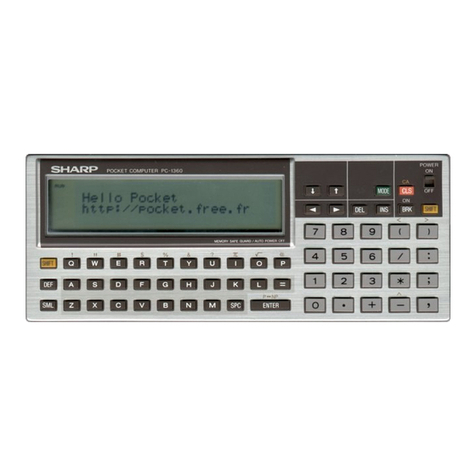
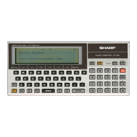
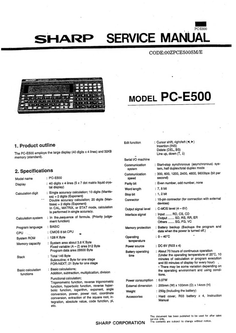
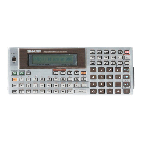
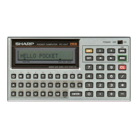
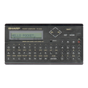
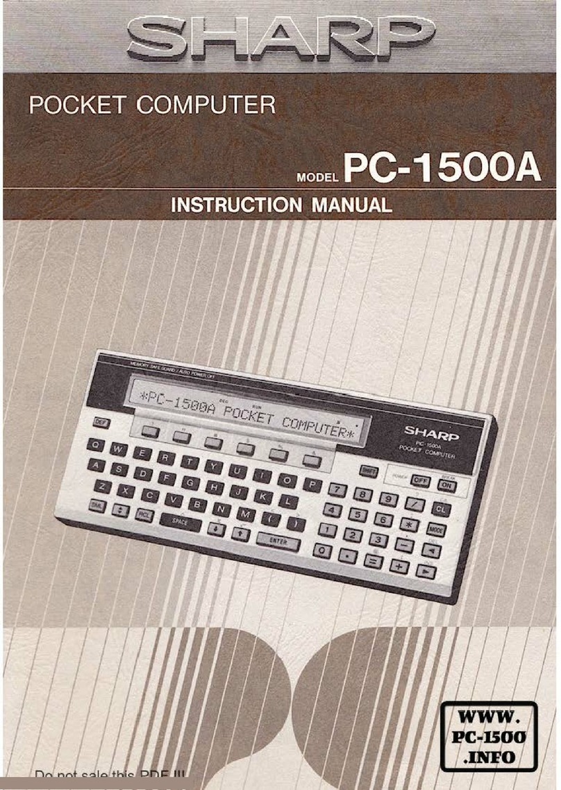
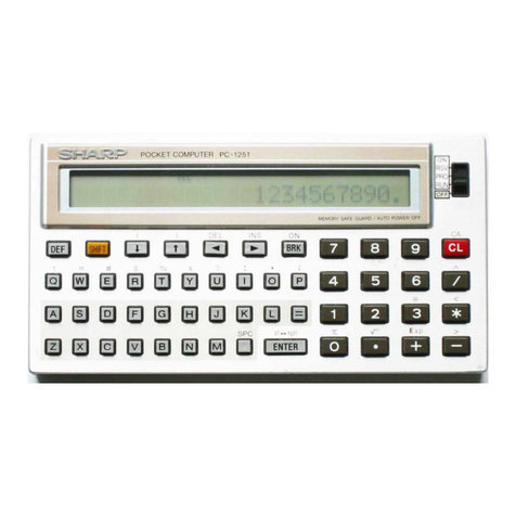
Sharp PC-E500S User manual

SHARP
1.
GENERAL
The
PC-E500S
is
a
modified
version
of
the
PC-E500,
having
the
easy-to-read
FSTN
LCD.
The
major
changes
lie
in
the
resin
key-top
and
the
hard
cover
installation
method.
2.
SPECIFICATIONS
*
Model
:
PC-E500S
*
Display
:
40
digits
x
4
lines
(5
x
7
dot
matrix
LCD
Parts
marked
with
"A\"
is
important
for
maintaining
the
safety
SHARP
CORPORATION
Arithmetic
capacity
Arithmetic
method
Programming
ianguage
-
CPU
System
ROM
Memory
capacity
Stacks
Basic
arithmetic
functions
>
Single
precision;
display)
10
digits
(mantissa)
+
2
digits
(exponent)
Double
precision;
20
digits
(mantissa)
+
2
digits
(exponent)
Calculation,
however,
is
performed
in
the
single
precision
under
the
CAL
mode,
the
MATRIX
mode,
and
the
STAT
mode.
:
According
to
the
formula
(with
the
priority
discrimination
function)
BASIC
:
CMOS
8
bit
CPU
:
512K
byte
>
System
area
.........ee
About
3.8K
byte
Fixed
variable
(A
-
Z)
area.........
312
byte
Program
data
area
...............
28,600
byte
:
Totali45
byte
Subroutine
..............6.
4
byte
for
one
step
FOR-NEXT
............--
21
byte
for
one
step
REPEAT-UNTIL.........
7
byte
for
one
step
WHILE-WEND...........
8
byte
for
one
step
SWITCH-CASE-DEFAULT-ENDSWITCH
Per
reece
here
animes
9
byte
for
one
step
.
Basic
functions;
Four
arithmetic
rules
Functional;
Trigonometric,
inverse
trigonometric,
hy-
perbolic,
inverse
hyperbolic,
logarithmic,
exponential,
angular
transformation,
power
raising,
power
root,
coordinate
transformation,
square
root,
ratio
of
in-
tegers,
absolute
value,
signed
function,
ratio
of
the
circumference,
and
others.
of
the
set.
Be
sure
to
replace
these
parts
with
specified
ones
for
maintaining
the
safety
and
performance
of
the
set.
SERVICE
MANUAL
As
sg
a
CODE:
007PCE500SSME
mopeL
PC-E500S
¢
Editing
functions
Serial
I/O
Communication
mode
Communication
speed
Parity
bit
Word
length
Stop
bit
Connector
Output
signal
level
Interface
signal
Memory
protection
Operating
temperatures
Power
source
Battery
life
Power
consumption
External
dimensions
Weight
Accessories
>
Horizontal
cursor
control
(<,
>)
Insertion
(INS)
Deletion
(DEL,
BS)
Line
up
and
down
(T,
1)
:
Advance
sync
(asynchronous)
system,
half-duplex/full-duplex
mode
-
300,
600,
1200,
2400,
4800,
9600
bps
:
Even,
odd,
none
:
7,
8
bits
:
1,
2
bits
:
15-pin
connector
(from
connection
with
an
external
device)
:
C-MOS
level
(4
~
6V)
INPUT
0.2...
cere
eessee
ener
eee
enters
RD,
CS,
CD
OUMOUT
occtesiaehs
eoceseca
SD,
RS,
RR,
ER
QHETS
....csccccrccccsconscre
er
seerones
SG,
FG,
VO
:
Battery
backup
(The
program
and
data
in
memory
are
protected
when
the
_
power
is
off.)
:0°C
~
40°C
:
Operating;
6V
=
(DC),
Alicaline
battery
(UM4)
x
4
Memory
protection;
3V
=;
(DC),
Lithium
battery
(CR2016)
x
1
:
Approx.
70
hours
under
continuous,
nor-
mal
use.
(10
minutes
of
operation
or
pro-
~
gram
execution
per
hour
under
tempera-
ture
of
20
C
with
50
minutes
of
display-
ing.)
The
battery
life
depends
on
the
operat:
ing
conditions
and
usage.
0.09W
:
220mm
(W)
x
202.5mm
(D)
x
14mm
(F)
(with
the
hard
cover
opened)
220mm
(W)
x
104.5mm
(D)
x
19mm
(F)
(with
the
hard
cover
closed)
:
340
g
(including
the
batteries)
:
UM4
battery
x
4
pcs.,
Instruction
manual,
CR2016
battery
*
ipcs.,
screwdriver
(for
replacing
the
memory
backup
battery)
This
document
has
been
published
to
be
used
for
after
sales
service
only.
The
contents
are
subject
to
change
without
notice.

PC-E500S
3.
System
composition
@)
Cassette
interface
Ft
aa
ee
et
foe
RS-232C
CE-124
Printer
&
cassette
interface]
Pocket
computer
PC-E500S
Level
converter
CE-130T
Personal
Soniplter
CE-126P
¥
RAM
card
CE-135T
euaae
eee
evel
bye)
mE!
Sense
-
required.)
is
CE-2H16M
(16K
byte)
\
CE-2H32M
(32K
byte)
Mark
><
shows
the
cable
©)
i
eHeehl
(oalseyie)
which
is
required
according
b
to
the
model.
Pocket
disk
drive
CE-140F
4.
PC-E500S
system
biock
diagram
Voltage
Detecter
IRQ
|
LCD
LE7766Q
|
V1-V6
| ,
DC/DC
VEE
|
Common
Columu
Columu
Carver:
Driver
»
Driver
—®
Driver
|
HD61203
|
HD61202
HD61202
REG
ka
+
|
VDD
=
|
|
|_|
Adrr.
AO-A17
15
Ceralock
|
PU
___¥Datadob7
|
+t
D
29MHz_|
scezoiscor
ceoces
|
#
SST
PCS
—
ee)
hh
KOO~KO10
|
,
1S
=
|
=-—
CEO
rt
EH
ez
|
pam
pe
Ty
boot
td
eee
aK
ROM
AT256
Coe
|
BF
SEES
ERRER
Key
Matrix
ino

5.
Memory
map
hy
aad
eae
&HOO000
oe
Coenen
&H10000
.
|
64KB
ead
RAM
card
es
&H20000
=
4M-ROM
CE3
(2Mb)
32KB
16KB
4
Reh
eayhece
gH40000
Fb
RAM
card
RAM
card
ai
&H47FFF
|
CE1
&H4FFFF
r
7
a
CEO
&HB0000
|
RAM
|
(32KB)
a
ea
&HCO0000
!
4M-ROM
CE2
OM)
re
&HFFFFF
§.
LSI
description
CPU
(SC62015)
pin
signal
description
Pin
No.
|
Signal
name
Signal
description
1
x1
O
Ceramic
oscillation
output
2
AZ
|
|
Ceramic
oscillation
input
3
X38
O
|
CR
oscillation
output
4
x4
|.
|
CR
oscillation
input
5
“YDD
re)
Display
power
(convertor)
control
output
6
|
VCC
POWER
(+)
electrode
input
pin
7
|
RESET
|
Reset
input.
Reset
at
HIGH
level.
8
GND
POWER
(-)
electrode
input
pin
9
TEST
|
|
|
Test
input
10
Ci
|
|
Cassette
signal
input
pin
11
CO
oO
|
Cassette
signal
output
pin
12
ON
|
|
ON
key
input
pin.
Normally
pulled
down
to
LOW
level.
13
WR
O
|
Write
clock.
Normally
HIGH.
14
MRQ
|
—_—
_
(Reserved)
15
K1i0
|
|
oo
|
|
4
KEY
input
pin
2
2
|
2
22
K17
|
|
|
23
DIOO
/O
!
:
|
:
Data
bus
3
|
pio7
|
vo
|
31
|
AO
|
O
|
|
Address
bus
49
A18
O
|
50
VDISP
—
(Reserved)
51
|
VA
=
4
52
oD
O
|
Clock
output
pin
for
display
chip
53
KO15
O
SIO
PRQ
(Reserved)
54
KO14
0
HIGH
with
the
ER
OPEN
command
from
SIO
A
PC-E500S

LPO
PE
CMAN
BCITEI
Ak
AGATA
LCWAT'T
2
ENTERS
ER
MAR
TATA
YT
TH
APE
SCTE
NTS
RT
SSP
GACT
AR
NEA
WR
RI
AEE
TEN
CNT
CEPT
AL
ANG
55
56
57
58
59
60
61
62
63
64
65
66
67
68
|
69
70
74
(72
73
2
82
83
84
86
87
88
89
20
(of
ces
OE
—~$
Gh
cn
Le-9)
to
O
85
ooh
1
<2)
PC-E500S
|
Pin
No.
|
Signal
name
i
i
nip
eS
ae
a
re
er
a
SS
ue
a
a
tt
KO13
©
KO12
KO14
KO10
IRQ
oOUT
CE7
CE6
CES
CE4
CE3
CE2
CEt
CEO
oA.
DIS
HA
RD
KO9
2
KOO
RXD
iT}
oH
GQ
dd
wethe
mom
ot
om
owt
in
a)
ae)
VO
O
e)
.
O
|
OO
|
~O};
|
|]
|
ooo]
es
HO
a
te
I-—--
OO
|
---O-O0O
|
Signal
description
SIO
RR
(Can
be
received
in
the
main
body.)
SIO
RS
(Main
body
send
request)
Key
strobe
signal
Low
battery
detection
input
pin
(Reserved)
ROM
card
chip
select
signal
(Active
HIGH),
10000~1F
FFF
Display
chip
select
signal
(Active
HIGH),
0O0000~03FFF
and
08000~OBFFF
(Reserved)
|
Internal
ROM
chip
enable
signal,
COOOO0~FFFFF
|
RAM
card
chip
enable
signal,
40000~7FFFF
Internal
RAM
chip
enabie
signal,
80000~BFFFF
|
(Reserved)
|
|
Key
sirobe
signal
|
SIO
RD
(Receive
data)
|
SID
SD
(Send
data)
|
|
CE-140F
data
input
pin
|
i
_
11
pin
DIN,
P-ch
open
output
ae
pin
DOUT,
P-ch
open
ouipul
|
14
pin
[02,
P-ch
open
output
;
11
pin
iO1,
P-ch
open
output
|
11
pin
ACK
|
11
pin
BUSY,
P-ch
open
output
:
(Reserved)
-
Display
power
(convertor)
contro!
signal
,
Low
battery
vailage
contro!
signal
|
SIC
CS
(Remote
station
transmission
enabie)
|
SIOCD
(Remoie
station
send
request)
_
|
SIO
PAK
(Reserved)
ee
Te
eT
et
nt
RHR
|,

7.
Low
battery
detection
circuit
This
model
is
equipped
with
the
low
battery
detection
circuit,
the
operations
of
which
are
described
below.
(Location
Nos.
of
the
parts
are
different
from
the
actual
ones.)
As
shown
in
the
figure
below,
the
output
of
the
voltage
detecting
IC
[LBIC
(RH5VA39A)]
turns
HIGH
when
input
voltage
VIN
exceeds
detecting
voltage
VD.
When,
on the
contrary,
VIN
falls
below
VD,
the
output
turns
LOW.
The
LBIC
(RH5VA39A)
detects
two
levels;
the
CAU
level
and
the
STOP
level.
For
that
reason,
a
voltage
applied
to
the
input
pin
(2
pin)
is
divided
by
R1
and
R2,
and
R2
is
turned
on/off
by
the
CAU
signal
of
G.A.
When
the
power
voltage
falls
below
the
CAU
level,
as
shown
in
Fig.
3,
the
BATT
symbol
lights
up.
When
it
falls
further
below
the
STOP
level,
the
BATT
symbol
goes
off.
To
detect
the
CAU
level,
the
CPU
E3
is
turned
on
(LOW)
and
the
CPU
IRQ
pin
state
is
checked.
(If
the
IRQ
pin
is
at
LOW,
the
symbol
lights
up.)
:
When
the
CAU
level
is
detected,
the
CAU
pin
is
turned
off
(HIGH).
(When
the
CAU
E3
is
turned
off,
resistance
is
not
divided,
rising
the
potential
at
BIC
2
pin
and
turning
the
output
from
LOW
to
HIGH.)
Then
the
CPU
IRQ
pin
is
checked
again
to
check
the
STOP
level.
After
detecting
the
STOP
level,
ON
key
and
RESET
key
are
made
invalid.
7
VCC
VCC
[Fig.
1]
Ag
no
ePuL
i
{
res
LB
A
CPU
E3__
hoicel
|
IRQ
B
(V)
TIN
oo
Power
voltage
(V)
\.
Voltage
detection
IC
operation
Symbol!
lights
up.
[Fig.
2]
[Fig.
3]
Low
battery
detection
circuit
check
CAU
level
VCC-GND:
4.2V
-
4.6V
STOP
level
VCC-GND:
3.8V
-
4.2V
8.
Current
consumption
check
Power
source:
11-pin
connector,
+5V
-
OV
applied
to
VCC
(2
pin)
-
GND
(3
pin)
Current:
At
ON
(BASIC
mode
with
">"
displayed),
3.29
mA
or
less.
At
OFF
(Power
OFF),
22.8
uA
or
less.
Reference
PC-E500S5
[__[eseration
|
display
|
DC-DC
=
|
converter
3
pvoo
|
075m
A
TC4S81F
|
TC3WO1F
§-1.
Current
consumption
and
low
battery
voltage
detection
Ammeter
Turn
on
the
main
DC
|
=
_
power
(+6.3V
40.1
V).
a
Ee
While
pressing
ON
key,
press
RESET
key.
*
Press
Y
key
to
initialize
the
internal
RAM.
Press
PF1
key
to
go
into
the
BASIC
mode.
*
Check
">"
display
and
|
check
the
current
value.
|
(The
current
should
be
|
3.77
mA
or
less.)
Set
the
DC
power
to+4.1)*
Check
that
the
BATT
|
+0.05V.
symbol
lights
up.
:
|
4
|°
Set
the
DC
power
to,*
Check
that
the
display
is
+3.7V+
0.1V.
out
4
i
eee
ne
ewww
we
ee
eee
ew
eee
eee
5
Return
the
DC
power
to
|
*
Check
that
the
display
is
|
+6.3V
+
O.1V.
|
out
and
check
—
the
|
:
current.
(The
—
current
|
|
|
should
be
22.8nA.)
1
6
|
*
Disconnect
the
1i-pin
|
|
connector.
|
|
the
11-pin
connector
with
|
a
3.9KQ
resistor
for
6
|
sec.
|
Note:
if
there
are
any
data
or
program,
save
them
in
advance
to
this
check.

PC-E500S
8-2.
Backup
current
detection
Ammeter
DC
power
+3V
[
[Operating
procedure
1
1°
Set
the
DC
power
to
+3.0V
+0.1V.
*
Apply
a
probe
to
the
|*
Check
the
current
value.
backup
battery
terminal
(0.1
nA
~
2.38
LA)
of
the
set.
(Be
careful
not
|
to
mistake
the
DC
power
polarity.
The
positive
(+)
terminal
should
be
brought
into
contact
with
the
battery
terminal
from
the
side,
not
from
the
above,
and
the
negative
(-)
terminal
should
be
connected
with
the
soldered
section.)
*
Disconnect
the
probe.
&-3.
Built-in
RAM
memory
protection
function
check
@
Release
the
RAM
card
cover
lock
switch
and
turn
off
the
power.
@
Set
the
builtin
RAM
memory
protection
switch
to
B
and
remove
one
UM4
battery.
@
Connect
2
pin
ana
3
pin
of
the
jii-pin
connector
with
a
3.9KQ
resistor
for
6
sec.
+
Connecting
time:
6
sec
@
Install
the
UM4
battery
which
was
previously
removed
to
the
original
position,
set
the
RAM
card
lock
switch
to
the
lock
position,
and
press
RESET
key.
©
Check
that
"NO
MEMORY"
is
displayed.
(Check
of
the
memory
protection
switch
function)
©
Set
the
built-in
RAM
memory
protection
switch
to
A
and
press
ON
key.
@®
Check
that
"MAIN
MENU”
is
displayed.
(Check
of
the
memory
protection
function)
9.
Diag
Entering
the
diag
mode:
Turn
of
the
power,
keep
pressing
key
and
CJ
key,
press
key.
Release
key,
then
release
|
SH!
FT]
key
and
LJ
Key.
Diag
Menu
1
diag
4:aging2
7:ESD
2:LB
5:RAM
8:diag(menu)
S:aging
1
6:FCC
ee
(1)
Diag
check
e
Key
input
(5)
LB
check
3 key
oe
(3)
Aging
1
4
key
input
(4)
Aging
2
(5)
RAM
check
6
Key
input
(6)
FOC
check
(key
input
>)
Esp
check
(8)
|
8
key
input
(1)
Diag
check
Main
menu
|
1
key
‘oe
LCD
check
Cross-stitch
display
1
(LCD
left
upper
corner
lights
up.)
|
ENTER
key
|
Cross-stitch
display
2
(
Inverted
cross-stitch
display
1)
ENTER
key
ance
line
display
14
|
ENTER
key
Slanted
line
dispiay
2
(Inverted
sianted-iine
display
1)
ENTER
key
Rain
drop
display
(Lower
half
of
the
screen)
ENTER
key
@
ROM
check
a
|
i
*
ROK
check
i
PC-E560S
Ver,
08
om
peg
are
ere
OK
Ss
|
|
*
ROM
OK!
*
}
CE
key
{
ierror
|
ppeme—>
|
x
ROM
error!
x
PC-E500S
Ver.
08
x
ET
Corwin
any
OME
aaa
EES
|
i
The
second
line
{
inverted
display
Jaddress
=
XXxXxxxX-XXxxxxxh
!
Error
address
}
check
sug
xxh
(true)
xxh
(err
)
|
Sum
data
ca
atel
C-CE
key
twice.
|
I

PC-E500S
@)
RAM
check
©
Card
RAM
check
—_eeea
ee
—_—a—a—a——y
|}
$$$
|
*
ROM
OK!
*
}
Card
present
—————
|
x
RAM
check
*
PC-E500S
Ver.
08
x
CARD
RAM
check
x
xxKbytes
i
aie
Ra
ey
a
a
a
aan
ER
|
aaa
|
Card
capacity
display
fone»
|
x
ROM
OK!
*
|
The
third
line
inverted
aces
|
{
*
RAM
error!
*
[
display
[
|
address
xxxxxxh
data
xxh(true)
xxh(err)
|
Error
address,
data
OK
|
C-CE
key
twice.
!
*
NO
CARD
*
|
|
|
|
|
|
ENTER
key
*
RAM
OK!
*
To
(7)
KEY
check
[
|
*
ROM
OKI
*
}
PC-E500S
Ver.
08
RN
EE
coeeehe
VRS
emer
teats
ceri
fei
eo
AT
|
ENTER
key
-——
—_—_—a—o
ee
end
1
lerror
|
i
}———>
|
*
CARD
RAM
error!
*
xxkbytes
|
The
second
line
|
inverted
display
|
address
xxxxxxh
data
xxh(true)
xxh(err)
|
Error
address.
cata
Pe
|
OK
|
C-CE
key
twice
ee
a,
iene
Tet
en
Cee
@)
11
pin
check
*
CARD
ROM
OK!
x
*
LIPIN
check
x
el
en
ee
eee
ee
catEEEEE
SSIES
|
ENTER
key
|
$$
$<
$
$< <$
$<
I
|
—_——
|
jerror
|
|
The
second
line
f————>
|
*
JIPIN
error!
*
|
inverted
display
|
check
No.xx
xx
(true)
xx
(error)
|
Error
No.,
data
eas
C-CE
key
twice.
——_—
eee
ae
OK
—_—————
7
KEY
check
————n
nn
een
i
*
1IPIN
OKI
x
|
|
KEY
Menu
i
|
|
:
Ful
key
check
|
ENTER
key
1
2:
Simplicity
key
check
EXXKKKKKAKKAKKKAKKAKK
|
|
1
key:
All
keys
check
2
key:
Simple
key
check
&
15
pin
check
A
SC«i
rer
;
|
|
t
|
|
*
I5PIN
check
*
|
a
|
|
[
|
|
*
KEY
check
*
| | |
|
|
|
eK
j
"x"
of
the
pressed
key]
|
Da
nr
|
|
is
displayed.
[
|
i
xxx
|
Indicates
the
key
to
|
|
j
———
oe
La
nner
HE
Pressed.
i |
lerror
| |
The
second
line
|
Correctkey
|
|
jum
|
x
I5PIN
error!
*
|
inverted
display
eee
eee
EE
EEE
{
j
|
check No.xx
xx
(true)
xx
(error)
[Error
No..
data
|
}
incorrect
key
|
i
Es,
|
|
Bie
eee
|
|
*
KEY
error!
*
|
The
first
line
|
40K
|
C-CE
key
twice.
i
[|
rocacex
[inverted
|
————<—
| |
|
display
|
|
| i |
|
xxx
|
|
|
x
J5PIN
OKI
*
| |
t
Ba
end
|
|
|
|
+
All
key
end
IPress
the
correct
key.
|
a
|
|
La
rh
|
*
KEY
OK!
*
|
|
|
ENTER
key
|
¥
j |
'
er
en
ee
ee
ae
RE
|
|
ENTER
key
‘
To
Main
menu

PC-E500S
(2)
LB
check
*
Low
Battery
check
*
|
|
|
|
a
ne
|
|
Caution
lavel
Low
Battery
check
*
|
x
*
Low
Battery!
*
BATT
symbol
lights
up.
Pa
[
Fatal
level
{
Power
off
(3)
Aging
1
|
Cross-stitch
1
(LCD
left
upper
corner
lights
up.)
Cross-stitch
2
(inverted
cross-stitch
1}
|
Ne
j
counter
xxxxxxxx
j
Rotation
display
}
*
ROM
check
*
|
{
[
|
PC-E500S
Ver.
08
|
|
|
lerror
|
counter
xxxxXxxxx
b>
|
*
ROM
error!
*
Sree
ie
se
eee
ee
counter
XXXXXXXX
|
*
ROM
OK!
*
H
|
PC-E500S
Ver.
08
an
ee
erErKY
ONY
l
H
|
|
j
|
ean
‘
[ae
8
E
counter
XXXXXXXX
fox
ROM
OK!
x
i
%*
RAM
check
*
|
PC-E500S
Ver.
08
|
ferror
|
counter
xXxXXxXxxx
p>
|
ROM
OK!
x
|
*
RAM
error!
*
ee
ee
ee
|
OK
|
C-CE
key
twice
Le
ee
counter
XXXXXXXX
*
ROM
OKI
x
*
RAM
OK!
*
ees
ear
ee
|
|
{
ee
ee
eee
|
ete
NONI
nee
ROUND
STS:
ANGLO
SY
I
GEAR FORE
CIES
QUNIEI
AICATEL
MIRESET
RIA
OH
NRE
AREY
CED
SEO
YAM
UGLY
MOORE
SERN
Bl
ONS
"ROT
SERED
MEN
Ne
AMEE
SOC
STR
NPP
Coren?
el
GEES
GRSRUTAG
SERENE
SERPS
NCI
eatery
Suri
Slee®
MLE
SEI
ERE
GENET
EUTEY
j
The
second
line
j
inverted
display
j
laddress
©
XXXXxXxX-xxxxxxh
!
Error
address
|
[check
sum
xxh
(true)
xxh
(err
)
1
Sum
data
|
Marereteerrnseein
lnc
remnants
$
0K
C-CE
key
twice
i
The
third
fine
inverted
|
display
|
address
xxxxxxh
data
xxh(true)
xxh(err)
|
Error
address,
data
(4)
Aging
2
OCR
REMIT
TET
HE
EEE
AAMT
CMR
SENATE
LOC
TOE
ECTS
SCA
COD
MN
ANE
ON
SON
ST
ONS
OE
A
A A
a
a
a
a
A
A
Te
A
Sat
PA
OLE
Clinimieh
AMS
A
SP
ABOU
TA
CeMPrED
NANTES
EWA
RUE
GG)
Ket
CHAP
ARETE
cmH
MNCS
ETE
|
Cross-stitch
1
(LCD
fett
upper
corner
lights
up.)
Cross-stitch
2
(Inverted
cross-stitch
display
1)
—
a
aaa
TS
|
counter
XXXXXXXX
Rotation
display
|
|
|
|
ee
ee
ne
4
About
50
sec
later
SS.
ee
er
f
counter
xXxXXxXXxxx
|
Rotation
display
|
x
ROM
check
*
|
|
|
j
|
PC-E500S
Ver.
08
[
[
ferror
|
counter
xXxxXXxXxxx
bp———>
|
x
ROM
error!
*
jaddress
=
XXXXXX~XXKXXXh
}
check
sum
xxh
(true)
xxh
(err
)
j
The
second
line
|
inverted
display
|
Error
address
|
Sum
data
OK
2
|
|
counter
xxxXxxXxxx
|
*
ROM
OKI
x
|
|
O-CE
key
twice
PC-E500S
Ver.
08
|
i
—_____-—--__
{
|
|
counter
xxxXxXxxXxx
}
x
ROM
OKI
x
|
*
RAM
check
x
|
PC-E500S
Ver.
08
|
{
i
ferror
|
counter
xXxxxxxxx
p>
|
«
ROM
OK!
x
|
«
RAM
error!
*
I
display
|
pO
}
t
{
¥
OK
;
C-CE
key
twice
OTE
AW
UIE
ERE
ETERS
TACTEM
=|
PASAT
SBE
counter
XXXXXXXX
*
ROK
OK!
x
*
RAM
OK!
x
a
KIN
Ae
wl
eT
RUNS
SADR
-C
RETO
SEIS
(5)
RAM
check
RAM
WRITING
|
et
SED
GH
se
RAM
VERIFING
!
ee
a
ld
;
error
on
RAM
VERIFY
oe
ae
*
RAM
error!
*
j
display
baddress
xxxxxxh
date
xxh(true)
xxh(err)
|
Error
address,
data
|
C-CE
key
twice
4
To
Main
menu
So
ere
mre
Loe
jae]
as)
|
winute
FAIT
Oc
ce
ee
Merinee
sraremtht
Mpeeete:
Spm
|
|
The
third
line
inverted
|
address
xxxxxxh
data
xxh(true)
xxh(err)
|
Error
address,
data
|
The
third
line
inverted

RAW
YERIFING
!
feet
|
I
|
ee
ferror
|
p———>
|
RAM
VERIFY
|
*
RAM
error!
*
|
display
|
address
xxxxxxh
data
xxh(true)
xxh(err)
|
Error
address,
data
|
fe
en
on
OK
|
C-CE
key
twice
OO
i
4
RAM
WRITING
|
To
Main
menu
re
ae
se
RAM
VERIFING
!
ee
OS
es
j
display
laddress
xxxxxxh
data
xxh(true)
xxh(err)
|
Error
address,
data
OK
|
C-CE
key
twice
{
To
Main
menu
[
|
|
|
error
eee
|
RAN
VERIFY
{|
*
RAM
error!
*
i
display
i
}address
xxxxxxh
data
xxh(true)
xxh(err)
|
Error
address,
data
i
Gea
4
OK
|
C-CE
key
twice
eee
|
+
+
RAK
OK!
*
To
Main
menu
RCRD
Nerney
MPEDetHS
Neca
AM"
|
|
|
ee
eens
|
ENTER
key
To
Main
menu
(6)
FCC
check
erro
-nkn—_—_—
ee
|
|
————
|
HHHHHHHHHHHBHAHHHHHHHWHHAHAKHAKHHHHHH
|
|
HHHHHHHHHHAHHHRH
HARE
ARH
|
|
HHHH
HHH
HHAHHAHRAH
HARA
RRR
|
|
HHHHHHHHHAHHABHHH
HARB
HAAR
|
Koper
senspensnseeersaceerssnee
One
line
of
“"HHHH---HHHH"
is
printed
in
the
CE-126P.
One
line
of
"HHHH---HHHH"
is
printed
in
the
CE-515P.
ncn
nerd
|
|
|
|
|
|
|
|
|
The
third
line
inverted
|
The
third
line
inverted
{
The
third
line
inverted
eee
PC-E500S
(7)
ESD
check
ESD
menu
CL
——————————_——L—
|
ESD
Menu
|
|
i:write
MAIN
RAM
2:write
CARD
RAM
j
|
3:read
MAIN
RAM
4:read
CARD
RAM
|
S:write/read
MAIN
6:write/read
CARD
|
fern
ronal
]
1
key
input
write
MAIN
RAM
|
2
key
input
write
CARD
RAM
|
3
key
input
read MAIN
RAM
|
4
key
input
fp—————————)
read
CARD
RAM
|
5
key
input
write/read
MAIN
RAM
|
6
key
input
write/read
CARD
RAM
@
write
MAIN
RAM
SSS
|
|
MAIN
RAM
WRITING
!
|
a
t
To
ESD
menu
@
write
CARD
RAM
ns
|
CARD
RAM
WRITING
!
XXKbytes
TONE
TCE
STH
ee
ea
ee
Se
4
To
ESD
menu
@
read
MAIN
RAM
MAIN
RAM
VERIFING
!
erent
CHEE
ere
aT
eres
Aire
idee
CRT
error
|
|
j
MAIN
RAM
VERIFY
i
The
third
ling
invertes
{
*
RAM
error!
*
i
display
{address
xxxxxxh
data
xxh(true)
xxhCerr)
|
Error.address,
data
+
OK
|
C-CE
key
twice
To
ESD
menu
L
To
ESD
menu
PC-E5008
®
read
CARD
RAM
—————
+}
Card
present
CARD
RAM
VERIFYING
!
xxKbytes
ee
ee
is
eS
SE
ED
Se
Card
capacity
display
No
card
*
NO
CARD
x
ee
ne
dN
|
y
ENTER
key
To
ESD
menu
ta
mr
a
|
error
|
f-——>
|
CARD
RAM
VERIFY
xxKbytes
|
The
third
fine
inverted
|
|
*
RAM
error!
*
i
display
|
J
address
xxxxxxh
data
xxh(true)
xxh(err)
|
Error
address,
data
NT
40K
|
C-CE
key
twice
To
ESD
menu
To
ESD
menu
©)
write/read
MAIN
RAM
ern!
|
i
|
i
a
aa
TEES
|
i |
[
1 |
MAIN
RAM
WRITING
|
|
i
|
|
1 |
i
j
CR
OL
|
i
{
[Et
eT
|
1
|
[
}
|
MAIN
RAM
VERIFING
!
|
i
|
{
I
|
|
i
ee
TTT
|
i
i
|
l
|
|
—————
ee
ee
ee
ee
gE
{
lerror
|
|
i
pome——>
|
WAIN
RAM
VERIFY
|
The
third
line
inverted
[
|
|
*
RAM
error!
*
1
display
|
}address
xxxxxxh
data
xxh(true)
xxh(err)
|
Error
address,
data
a
eee
ea)
eee
es
OK
|
C-CE
key
twice
Interrupt
with
C-CE
key.
(To
ESD
menu}
\
To
ESD
menu

©
write/read
CARD
RAM
|
CARD
RAM
WRITING
!
xxKby
tes
CARD
RAM
VERIFING
!
xxKbytes
a
a
revel
nS
error
|
}
CARD
RAK
VERIFY
xxKbytes
|
The
third
line
inverted
|
*
RAM
error!
*
j
display
|
address
xxxxxxh
data
xxh(true)
xxh(err)
}
Error
address,
data
ee
|
eA
Mp
|
Semi
GA
SEE
TD
SR
HOON
SG
A A
ST CH
NA
AT
SERMON)
pti
MAMA
AACMAERES
WORT
ret
CE
rele
ee
|
bed
(kK
|
C-CE
key
twice
interrupt
with
C-CE
key.
(To
ESD
menu)
1
To
ESD
menu

tie
(8)
Diag
check
(menu
form)
Perform
each
check
of
(1)
diag
check
individually.
Diag
menu
fe
ee
eee
ee
|
*
check
list
2
*
|
|
1:
LCD
check
2:
ROM
check
|
|
3:
RAM
check
4:
KEY
check
|
}
5:
lipin
check
6:
15pin
check
|
|
1
key
input
(1)
LCD
check
of
(1)
diag.
|
2
key
input
pe
——————_
(2)
ROM
check
of
(1)
diag.
|
3
key
input
(3)
RAM
check
of
(1)
diag.
|
4
key
input
{7}
KEY
check
of
(1)
diag.
|
5
key
input
(4)
11
pin
check
of
(1)
diag.
j
6
key
input
(5)
15
pin
check
of
(1)
diag.
After
completion
of
each
check,
the
controi
returns
to
the
diag
menu.
wa
—
PRQ|
CN2
&
fo
T1PIN

¢
RAM
card
address
map
00000
2KB:
40000H~407FFH
4KB:
40000H~40FFFH
8KB:
40000H~41FFFH
16KB:
40000H~43FFFH
32KB:
40000H~47FFFH
64KB:
40000H~4FFFFH
40000
4FFFF
FEFFF
*
The
address
check
is
performed
from
the
lower
address
to
the
higher.
The
error
address
which
is
found
first
is
displayed.
*
Details
of
the
error
code
(Example)
In
11-pin
check
error:
Error
code:
1
13
01
t__—
Error
value
(Error
output
data)
Norma!
value
(Normal
output
data)
Check
No.
Refer
to
the
11-pin
check
code
table.
Output
port
Input
port
ao
|
[ton
oa
PO.
0
0)
0)
Oa
a
[|
8
in
the
above
table,
if
the
output
port
signal
is
"000001,"
the
input
port
signal
"10011"
is
normal.
("100114"
in
the
binary
system
is
"13"
in
the
hexadecimal
system.)
if
11-pin
check
error
code
is
"1
13
01,”
the
input
port
signal
should
be
"43
(10011)",
and
"01(00001)"
means
it
is
an
error.
|
That
is,
data
at
ACK
and
1O2
are
errors.
¢
11
pin
check
code
table
Output
port
|
|
input
port
,
No.
BUSY!
Din
|Dout|
102
|
101
|
ACK
|
Din
|
Dout}
102
|
tor
|Nantal
ofofe;e}olejoloto
|
os
|
105
0.
1{+ioj,;olf1{i
|
19
|
ofpopopr
pops
popefs
|
fos]
sfepols|+i+fofolti+|s
0
1
0
|
oO|;|c|a
@
Oo
fe
.
roe
a
Blalelela|
ale
lf
=|-|-]
Fa
Boe
ma
cla
|
ale
co|;™
on
a;—
+
mo
mp
a
a
ae Ae
“=
+/O
Sak
Ae)
—
“||
BE
wh
|
mt
=
2
co
ake
fd
{==
&
beads
—
aes
aes
ae
ae
ia
Po
Bie
eek
|
ok
ft]
amet
|
CD
Ojr!|ol]r|
ny
&
woh
@
|
©
oO}
O
—-~1|O|O};0O
-)
im
jo
=|
=|
=
|
=|
=
ome,
onk.
aq)|—]—-
il
nie
ne
ba
.
=f:
7
:
Cc)
|
+
oe
ee
aE
--E
ele
slele
BES
Boe
ce
ee
Oo
BSCE
e-EE
viral,
—
aa
+
|
EB
|
|
16
Gg
o|
oO
ims
ae
—
med
—
Esa
ne
oe
ae
ine
poe
ns
s|a
—
“J
aa
PC-E500S
cs
mm
Ee
a
2]
8
ep)
i)
o
a”)
m
=
a8
i
ho
|
oO;}o
ale
aud
=
a
“
ae
isle
Nm
|
+
on]
aes
fa
bc
ba
fe
-
=
a
aie
sis
bl
aioe
or
oie
oe
o)
+}o]=
“fe
ee
“EEE
sislae
at
|
O
©
mo
al
>!
‘-)
ar
oO
=|
©)
“|=
)-
le
:
|
ele
“I
@
a
G
fd
zi
|
a
ie
.[
tbo
a
aie
m|
©
f
|=
©
>
O
~
Tt
mh
|
ek
ook,
=
=|=|
pom
|
oP)
O
ms)
o
eI
jt
)*)
©
10.
Note
for
servicing
4.
Electrostatic
sheet
attachment
insulation
sheet
Attach
to
the
rib.
Allowance
of
attachment
shift:
4
De
not
extend
from
the
PWB.
Le
within
2
mm
in
left
and
right,
up
and
down.
=}
18
ve
‘
a
+
—
——-
Thi
u
a)
TS
mi
lt,)~C~<C—s~
RS
EE
mse
5
LAY
AR
SK
Se
KOC
YL)
LL
f¢
J
onot
exien
!
ARES
RS
7
ty
N
trom
the
PWB.
F
WLGZE
DF;
oe
yy
Yl
Hy
>
4
=
|
4
e
Press
with
your
nail
®
along
the
PWB.
\
i
|
Fit
with
the
boss
hole
and
Electrostatic
|}
|
Fit
with
the
boss
hole
and
=
@ttach
alang
the
boss.
sheet
iL
CAB
atiach
along
the
boss.
mb
ee
Fit
with
the
boss
hole
and
attach
along
the
boss.
ny
N
i

PC-E500S
2.
Nut
holding
tape
attachment
reference
After
inserting
the
nut,
attach
according
to
the
reference
shown
below:
Reterence
Nut
holding
tape
3.
Battery
holding
cushion
attachment
reference
;
Battery
holding
cushion
Seribed
line
Scribed
line
s
os
t
-
LLL
AS
;
ets
.
1
(Reterence
=
os
Reference
>
\
Battery
cover
Attach
within
the
range
of
the
scribed
lines.
4,
Buzzer
attachment
@
Remove
the
separation
sheet
from
the
buzzer
spacer,
and
attach
the
buzzer
to
the
spacer.
7
Buzzer
spacer
Buzzer
(=
{NS
yc)
(
|
(C
yy
Fit
R
and
attach
properly
so
that
the
buzzer
lead
wire
is
in
the
upper
side.
Pee
NER
R
RE
RT
ATT
ea
ecPs
Hoe
@
Attach
the
assembly
over
the
HD61203
on
the
PWB.
Attach
so
that
the
lead
wire
is
in
the
upper
side.
Center
Reference
==»
Align
the
spacer
edge.
@
Solder
the
lead
wire
and
fix
with
tape.
Ces
6.
Note
for
handling
PWB
&
Jumper
wire
process

@®
Electrostatic
capacitor
process
and
soldering
C12:
220
uF
¢
Be
careful
to
the
polarities.
|
©
When
soldering,
bring
the
capacitor
into
close
contact
with
the
PWB.
|
| :
¢
For
soldering
position,
refer
to
the
parts
arrangement
view.
(—
-—-
—
—|
ae
aA
4mm
@
Contrast
VR
solderin
*
Attach
duplex
tape
so
that
it
does
not
cover
the
VR
attachment
hole
and
does
not
extend
from
the
PWB
edge
and
the
FG
pattern.
¢
Solder
form
above
the
duplex
tape.
*
Do
not
apply
the
soldering
iron
for
more
than
3
sec.
(This
is
to
prevent
deformation
of
the
VR.)
Be
careful
not
to
deform
the
VR.
*
Put
the
VR
closely
to
the
PWB
and
solder
it.
FG
‘ial
VR
attachment
hole
peateeta
VR
ae
7
_
Duplex
tape
or
|
PWB
key
pattern
surface
@
11-pin,
15-pin
connectors
soldering
*
41-pin
connector
soldering
e
Attach
the
spacer
to
the
11-pin
connector.
¢
insert
the
11-pin
connector
to
the
PWB.
Solder
the
inserted
lead
wires
(x
2)
first,
then
solder
the
11-pin
lead
wire.
*
Attach
the
connector
closely
to
the
PWB
and
solder
it.
11-pin
connector
Spacer
Vv
PWB
pattern
surface
15-pin
connector
soldering
*
Attach
two
electrostatic
SP
to
the
15-pin
connector
lead
wire.
¢
Insert
the
15-pin
connector
to
the
PWB.
Solder
the
inserted
lead
wires
(x
2)
first,
then
solder
the
15-pin
lead
wire.
*
Attach
the
connector
closely
to
the
PWB
and
solder
it.
<———{5-pin
connector
<——-
Electrostatic
SP
(x
2)
PWEB
pattern
surface
Card
cover
SP
soldering
*
Insert
the
card
cover
SP
into
the
PWB,
and
solder
it.
*
Solder
perpendicularly
to
the
PWB.
*
Take
care
when
handling
after
soldering.
Card
cover
SP
-
Soldered
section
S—
Fit
with
the
pad.
©
Insulation
sheet
attachment
SF
Insulation
sheet
attachment
¢
Fit
the
insulation
sheet
hole
with
the
PWB
screw
hole
and
attach
it.
¢
For
the
attachment
position,
refer
to
the
parts
arrangement
view.
C15
Insulation
sheet
2a,
Sa
O16
X1
EVHILH
=
cmon?
|
=
834HF7
=
(IC2)
a
\
Screw
hole
Battery
terminal
insulation
sheet
attachment
¢
Fit
the
upper
edge
of
the
battery
terminal
insulation
sheet
to
the
PWB
edge
and
fit
the
left
edge
to
the
marking
pattern,
and
attach
it.
°
Attach
so
that
it
does
not
extend
from
the
PWB
edges.
PWB
edge
Mark
pattern
Battery
terminal
insulation
sheet
¢
Backup
battery
terminal
insulation
sheet
attachment
e
Fit
the
backup
battery
terminal
insulation
sheet
to
the
resist
ring
(reference
mark),
and
attach
it
from
above
the
backup
battery
terminal
(-).
AMUN
UNA
Resist
ring
(reference
mark)
e.
Backup
battery
terminal
insulation
sheet
Backup
battery
terminal
(-)
11.
LCD
wiring
diagram
--
OLX
eeoe
-
a
i)
~
(27P1N)
eet
ea
eS
ee,
SS
eo
Se
Sie
ee
ee
“SS
SUS)
Seis
eS
a
eee
=
wie
ee!
ae
eee
aie
leet
ea
a
eke
ole
et
et
ee
eee
ee
eee
Ss
Susi
<<
_
<<
ete
ae:
ee
Soars
Ge
Sera)
fe
2
Seay
eerie
Se
eo)
Seite)
6)
SS
tO
(Se
See
eee
Se
me
ees
Vs
~~
WA
oO
COO
(64PIN)
(8PIN)
a
|
(20PIN)
X1~X64
HD61203
(1)
Y1~Y64
HD61202
(2)
Y'1~¥'56
HD61202
Symbols
LOGIC,
AMSMBL,
TEXT,
and
Sign
are
not
used.
$5,
S6,
S7,
S8:
Y'64
a,
7
(12PIN)
SX
(11PIN)
<<
GB
\_)
B
Center
division
of
the
common
side
(27PIN)
PC-E5005
Sigel
wl
me
ee
ee
ce
tase
ee

PC-E500S
12.
CIRCUIT
DIAGRAM
aE
;
|
ae
HATS
OC
TTT
clin
inna
LET
a
Ae
uae
da
an
i
P7y
rae
oe
—m
ua
(LF77660)
AT
oe
aa
bags
bees
|
e
|
N
=
bE
©
_
meee
t
A]
NN
|
P—_
EA
=
a)
eg
OES
W
rs)
Pai
ae
=
h——}_
8
Q)
b—-
BCA
i
wee
WY)
wey
4S
LL.
a:
u
HA
5,
mm
—
Ow
te
re
of
Dy
be
eae
ve)
|}
<
my,
pare
qa
"tT
ais:
329
oe
4:
am
a
m
ron
=H
8
1S
os
v,
oy
wis)
o
§
BEY
!
=
ee
Q
\
|
=
=
esl
tet
oon
oh
ene
et
y—}-BEX
—
gf
O
Bicareszueecnen
ae
"
Ga
ae
Sie
eae
aaa
||
a
aan
VEE
v5
j
=
|
Os
=VYeec
S$C620:15CO!
(ESR-L)
RALIN-
KSw!
O.tu
o:4
“nameeanmnantn
teenie
trate
rename
teiteie
er
TC4S61F
TI
Converter
Trane
Ci7
680R
4700P
sl
C32
C34
RHSVAISA
0.01u
3|
x£Or!
i
i
Rit
Rov
2
See
Eee,
ci
ae
Oey
ee
04
PE
as
—
os
E
a6
DTAI44EuU
X
3
a7
|
.
|
BDICIi44Eu
R95
sa
celica
4.9K
|
'
{
|
SI
ee
eS
ee
a2
‘4
C2412K
2
aoa
ae
tas
te
a
eke
03
D
G
~tulOvtae
et
pee
(ae)
CI
=<
3
.
0
a
Ur
oe
ee
ra
IO
oO
01
eS
Ci24,
220u-
.
46:
ng
ao
és
o
ee
|
ree
Ae
ape
is
avs
[*
CEBEEEPPESRE
SEE)
SPBREEREEEE]
—
uw
ic
O
techie
__15
PIN
1)
PIN
+r
DAN202K
—+€-—
RB400D,
of
resistance
is
+-5%,.
Note
1:
Unless
otherwise
specified,
diodes
are
as
shown
below:
Note
2:
Unless
otherwise
specified,
the
accuracy
-16-

TAYK
CASGEF
=
A
DT,
av
=TC7S02F-
220uUF/10V
Seats
Attach
to
the
right
side
of
the
chip
electrolytic
capacitor
C
(x
2)
with
bond.
25C2412KS
Ae
protection
SW”
2
Surana,
“pasantenmnmsoinsnnsants
nso
giinnso
erin
RARDIN,
WANN
ietisebl
saniarnspnnesinp
oe
ate
anne
tn’
5
&
prone
nnminnenmnepannedavrnonersnndceetard
4B
Seo
eadacts
ontains
mtag
deere
stn
at
somata
ian
ig
Heart
SE
eae
Backup
battery
terminal
(+)
Sou
uickly
nol
to
remove
th
tetas
Sr
et
asians
a
gegen
Main
battery
terminal
B
Main
battery
terminal
A
Nana
nana
eoenenes
einen,
Soindnneis
[PC-U6000---
VHILHS5S4HF7-1
PC-E500S---
VHILH534HFS-1
PC-E§50:--
VHILHS34HFB-1
"ome
|
{
t
agents
ee
4996
toveasaatiree
y
i
1%
asiamcatninronemnscencnead
Piezo-electric
buzzer
POR
ANNA
ee
ie
rememennane
tie
agen
ceuscagemarn
pst
raster
wn)
Msc
tapansosten,
ag
gage
Vanier
it
Se
Anette
36
a
I
yi
Se
beaN
Q
New
cass
Wi
@
8
be
RS
od
om
he
gonad
®
Be
?
{
aro
As)
Meee
Bihnemennsercsincni
fie
Sopra
eietecoateesesmnneneysdaneRelalen
sci
anse
ond
Oy
Ccberusivcaien
ina
Main
battery
termina
Bee
NE
asi
OURS
ee
mac
eee
seal!
AERA
alunite,
cineumcepnirienenees:
§
EES
inssoneaaststaceoee
Sneek
ds:
Seopa
~~
pseu]
|
DAN
peony
Ge
orner
ofthe
PWB.

PCE500S
PC-E500S
14.
PARTS
GUIDE
Exteriors
=)
=
=
=)
A.
O
O
y
MUS
DKON
f/f
KU
yy
Uy
y/
QY,
Wy,
UN
eg
/
EOS)
,
«
IN);
NON
“
BES
WOON
YX
WN
NOI
\
yp
\)
“He
14
Sa
ft
ts
Wale
rs
|
DWelelsl<i'e
"al
a
sl
>
©
©
lA
on
“|e
5
=
a2
ps
|
5/4/4]
BO]
©
S|
@|
ol
&
Cc
Cc
cy,
c
a
foe
Ww
E)>/>]
ol]
|
|
3]
E
S|
|§
Z
alae
29|o18
ae)
©
|<
®
Lane
.
nd
E
E
EIS
o
=
o|
>
oO
bt
gs
:
|
O}
°
oe}
f
e
mj
@
S
|
3|
2
x<
|
@
H
®
:
aj
Lead
Ina
-
z
o)
O
|
= b
a.
ao.
ac
S
ac
O
G
Q)
nf
a
”n
uw
bs
re
QO
oe
or
Q
a
a8
D
Peel
2
ww
rea
>
=
=|
cic
2
a
P=
cj}
2
212
—
wm
3
=).21-2
|
©
oe
=
a
=)
3]*
as
9!
&
a
a)
|e
3
=|
21515
£
ca}
on]
«ch
D
elclcia)
|
De
QO}
{0
F
*
=|
5]
§
3
$13
“|
3]
o}
a
S
c
El=l=l8
rele
|x|
x
ee
AE
®
@
a|.O}
®
ajc
ZI
el
«
i
Ge
de
my
oN
<
<
3]
S|
@|
B]—
|S]
cls
ololo
ro
E|=
cS
Deis
AISIS
ol
ole}
“|
*]
2
of
€|-=}-=]-e]p-
21
ty
ddl
|
fixe
OW
«g
=
ree)
o)
2).
o)
S|
~
alc]
ol
8
6151S]
gl
a]
of
=
Olt
a|
|>lals
~|
O15
S|
8)
)
|<
S|
[es]
E)
EE
Els
<j)
jaiacioioy
ow)
|
4%
lo
a
SiolTlElelZ@|
[Ll
El
els
Al
.O}
4}
8)
8]
Bla]
AS
2}
foo
sis)
f=sf
US)
gl]
sj
9
5/2]
82)
2]
915)
5218/2)
SA
ix|
3
8/8
2
el
el
e/e/S)
2/2)
S|
(Sa
clH/2i
22
Siz
2
as
S|
o|
al
P|
P|
Of
PO}
4
od
3
Ss
2
2]c
&
al
al
aS
sl
ol
S)
5)
5)-S)
Els!
<5
elsia
=/5/5)
5
als
Sls
a
S
31-3)
-S)
ag
od
og
og
S|
oH
EE
Bley
|
27S]
5)
|
27.8]
24
2)
3
St
S18)
Sa]
|
leis)
8
|
Bt
ay
ats)
13)
3)
SSIES
Sale|
lal
8
=
al
4)
m=]
|
2)
2)
e)
Oe)
at
Sts
919)
9}
€}.<}.¢}
|
2}41)
|
sl
o
PS)
3/2)
515)
31
2/5/83)
3)
E/E]
€|
8]
Slt
slg)
B/S)
a]
e)
2)
2)
2/212)
oS)
2
2)
a
ad
|
84D]
5)
8)
S/S]
el]
El
S/S)
5
=|
=|
513/515)
3)
22}
2|
s|
s/4/8
BB]
G)
2)
SG]
Oi
ay
3}
Ol
G)
B)
S/S
=]
2)
213]
S|
SI
Sl
|
|
Bo!
5/S/
3)
35)
3)
G)
a)
|
2]
5)
S/S)
0
€]
8)
£]
6]
22
a)
co]
|G]
B]
oS]
2
Bl
al
|
Bl
&|
3]
|
S|
E]
S|
S|
5/9]
O}
ca]
A}aa}
SO]
H]alO]
alm}
Zz}
2]
2z/
HlOjalHjn/H}Z/ZjO}
aj
aa]
a)
ajo]
jo.
|
sc
[se]
S|
xe)
||
KO]
CT)
Thi
Z|
3)
To]
S|Ajajalo|T|-|ajajt
EE}
Llalajajaj>|>[OlO}o/
2/0
x
oe
a
ae
|
ii
We
be
xe
xZ
Pare
QAsOJAlojalo
Vlajolalololalo
olololololulololololofjolofojalojofafofOjOfo}ololojojojo
ololola
ezZlalajqjqyqjajqjaqyqjaqyaqja/a
Q.
a
|
Oo
x
|
—
|
ae
:
BS
Sax
=x
z=
2
z
z
z\z|z
z\z|z
mw
Slz|zj)2\2\z\z
=
“=
Lud
iy
,
x
LZ
m|co}o|
<<}
>
Tizfujulc|olmjo
S]O}m|
aj
<
OF|S|>|>
~e
<\a}<}<jm
rdiede-at-dt-de-db
at
Par
dt-
deat
et
\<\<\<
ai.
¢
<i
NUN
PARTS
CODE
PARTS
CODE
xO!
L/TO/WI
aD
DjO;OlOJO]
C/O}
wu)
OO;
<j)
CIO]
x
|
peo
Od
a
tic
~¢t-dt-G0-dt-dt-dt-¢t-dt-dt-dt
dt
dt-qt-di-df-¢0
46-40-4045.
¢
wee)
t-
40-90-04.
¢
<
”
(oe)
S
O
OO}
O}a|aj}
mM)
c]o
*-ar-Ge-@0-@n-@0-@0-
qT.
¢
NIN
ININT
AGIAN
NIN
TN
INI
NNT
eI
TIN
a
LAN
OTe
Le
N
IN
NTN
TIN
TNT
NUTINI
ett
bet
at
INT
et
tet
me
ON
TINTING
LN
TRS
NTN
NINN
INININOINININININININTOININIOlolNlolololNININININININININ|
]o}O/O]
NINN;
OlOJO/NIN|O]O]aNININININ|
O|NIOININ
olololololololololololololololololololololelaololololofofoOfO]ofolOfOfo]o]
OJOJOJOJOLO/O/OJOJOJOJOJOJO/OJO/O/O/O)O1O
NY]
PTT
FON
RS
PN]
PT
ETT
ET]
PNT
NT]
FONT
CRN
VD
CO]
ey
CODERS
CNT
ey
CPT
(ey
Oy
COTO]
PN
TP)
OTe
POT
WN)
CON]
Oy
(Oey
cre)
cre
reeyirey
rvey
ve)
creyies)
crvac
ao)
ten)
(eo}ivey
(oto)
0]
()
bt
ed
bees
be
wl~lwlwlwlalelen|wleale|wlalin]mlinlalalalulaledelalalR
[wl
a|a}a|a|ola|
ajo]
|
wo]
co]
co
wa}
a1]
Ht
|
1S]
09]
cop
PS
|
Ga
oo)
CO]
OT
rE
ee
TONNE
ON
|
et
Beet
mt]
ON
mt
|
TONG
tO
TON
LO
|
nlwolalaialmlcolole!<lolm|
mle]
al
male]
olwlm[
nN]
a][
olor
|
NW]
NN}
et]
Oo] og)
wo
olalolmlolalolololml[mimimimintlolnlololniclololalololololal|wlolofolojalala)
aJololaojola]
jojo
jole|ola]ojaaja
|e]
@
jn)
2)
90
mal
mat
mma
ena
ona
ena
Lena
feet
ena
|
maf
mead
eee
|
mma
f
mea
|
ema
f
ma
|
maf
td
emt
|
af
mt
Arf
ma
me]
mtd
mt]
med
a]
maf
tf
maf
mad
emt
mad
maf
ma]
mt]
nf
mt
|
mt
emt
|
mt
|
tf
ret]
et
mt
|
mt
mt
rt
|
tf
me
rt
ems
ma)
mt
ma
mat
SI)
rin
ical
ale
INiolnlrirlsislsinin|w/xrialN|zlaln|<)a)|a}alma|
N/a]
S|
S|IN|ININININ]
|S
/O]N/Q
IN|
N/O;O/N
ff
nd}
SE]
as]
SN
QUINN]
C/O
-Ll-
[Dia
Lin
|
aja
ol
|alwol|
a
cl
Sjw]-—|Ojwjnicia
2izjz
oles]!
Slwlalalalm)
o}sjae|e
lm)
Zjac|
zie
pX<|R
IRR
|
mo]
2
lec}
fe
jupet|
|
[|
lect
ei
cf]
|
fe
[Dla
jj
Zio
we
|
el
cic
plzloaloiznizlezja2f2})--lo
fu
cia]
ft
fo]
—
ff
—
fe
tt
as
ed
to
|
ale
NTC]
ft
Cf
rf tf
nt]
|
ma]
CO
Oe
|
LL
PO
Fe
x13)
co}
ofan}
sc}
se
lsc
fac]
Nie
}]
|
O]
xc]
><]
9].
9
NOP
INN
ad
Oy
Fea
Ole!
alcslade|
alla
eRe
IE]
a
Olaja
S|
7jalx/ojOiOiOle
slalalalalralala[ri
a
alsizlol|
ss}
S|
[Zz]
ja
jojaja
|r
jolojo7ya./o
QIAN
b
oe
mA
re)
ms
ol
N
COPS
UAT
OL
PS
|
COLD!
Ole
N
|
oo
CO]
Dj
OI]
A}
NI
WIP
O/H
Olt}
Qi
>
Hj
Oies
ed
bet
SrryTrrryrPr
*
PRATAP
arrer
TREE.
i
iL
NO.
xlsx
109(O]
Cj}
am]
O}m
|
it
ede
dt-ae-40-
40-40-4090
d0-
45.
¢
SUTIN
TNUINSTNT
INI
NUN
NUNIT
NTN
ENING
NUTINI
GQOlOlOlOJOlO/;O}OjO
WjiO
dad]
ad
|
add
bad
tad}
bet
|
CD
|
bad
|
ad
O}O
a]
ea
Oa]
map
on]
>
|
Ld]
LO
|
LO
7
O47}
00
CUE
ON
oo
LOO
feet
|
NE
Cop
emt
Q}oO
UL
Oa]
ON]
19}
9
CO
pL]
CLO
@
}co
tl
eslet]
Ola}
O]co|
Cj
}Oiet
voted
cof
uit}
O]O]o}t]
|
p<cpN]udjuiN
Mla
|
Msc}
xe
fst
[sci
scp
sc
[QO
=
Zizlzi
al
aei
citi
ci
cic
<
|
—|-—ja
aia
jaja[myo
cS
pe
let
|
non]
nian] o}aa]
ke]
|]
N
om)
arp
Packing
material
&
Accessories
52
53
|
5a
|
2
oan
—-?0-
=o=

PC-E500S
Packing
material
&
Accessories
PRICE!
NEW
|
PART
RANK
ee
DESCRIPTION
»>
©
PRICE|
NEW
|
PART
NO.
|
PARTS
CODE
DESCRIPTION
SS
—
——
fT
2IMSPRC1020ECZZ
|
AB!
|
C_
[Card
lid
spring
-——3IMSPRO12776CZZ
|
AA
|
1|_C_
[Connector
spring
(for
15pin
connector).
SSCS
———4IPGUMSIO4ECZZ
|
AB
||
[Rubberconnector
CSCS
-
GIRSPAP
TOP
OE
C72
IAC
|---|
O.
Suncato
bummer
——"EIPSPAPI2E9CCZZ
LAA
|
|_
©.
[Spacer
for
llpin
connector.
——SOS—=—“CS~Ss~—‘“‘“‘<;727
SDSS
a
PTRERLOGZECZ?
CAA
CLD
itapeRG
ee
——$sIPTETLIOG9ECZZ
|
AB
||
©
|PWB
insulation
sheet
——=S=~C~C<“<SsSC‘C=‘<iCiC<C<CSCSCSS
sIPZETUIBEICOZZ.
|_AA
[|
GC
linsdlaton
sheet
=
es
—JOIOGNCWLOOTECIA
|-AG
||
C
Connector
(lipiny)
——SSSSCOSSCOCOCTSC
NL
—TiTOCNCWI368CC1E
TAM
11
C_
[Connector
(I5pin)—S—s—sS—SSSSSSSCSCSCSCSCSCSCSCSCSSS
EEN]
-—T2]OTANZIOS0ECZZ
|
AC
|
[_C
Iterminal
for
back
up
battery
PSSC‘CS;7;7;3
SC
C;<;7
SPE
>
wIOTANZ
LUT
ROCCEA.|
AC.
|
C
(powertemimal
-——TalOTANZ1583CC07
LAB
|
1_C_
[Battery
terminal
CSCC
“aeIRAUCMBROSUCCOL|
ADl.
|
Bo
lease
ee
—eIROTCTION3CCZZ
TAB
|
C
[Capacitor
Oinf)CCtCSC“SsSsCSsSSSC“Cs‘“‘<CSt*S*S*CSS
«ESE
,7,8,9,10]
|
FIRES
EZ2Z7IDECTA
LAB
||
lCapacitor
(IOWV
22007)
—sss—i—i—‘;SSSSOCSSCSOCSCSCSSCSSSST
2)
-—7a[RCRM—IO1L7TCOZZ
LAE
||
8
[Crystal
(29M)
SS—SOSSSSC‘C‘C;S
Sg
IRMPTO41040C3
3
1
AB_|
1B”
[Block
resistor
(O0KNX4
25%)
sSC—“‘“‘“‘;72C!S!SSTT
BRI
—~soIRTRNHIOO4ECZZ.
|
AE
|
|B
IConverter
transformer
SSCS
——TIRVR-ZS4SE00CZTZ
LAF
||
8
[Variable
resistor
(50KM)——SsSst—SsSCSC—C—CSSSCSCSCSTTSTSTT
OLR
—331VECCCYIHHI213
1
AA
||
[Capacitor
(50WV
120PF)—sstC‘;CSC;SCSCSS*”!TTT
CR
Se
|
241VCCCCYIHH470J
|
AA
|
[|
C_
[Capacitor
(SOWV
47PF
[C15,16]
H—SeIVEEAPEICWS35M
|
AC
|
|_C
[Capacitor
I6WV
3.3sF)
Ss
SCOCSCSCSSSSS
CT
——SEIVCEAPELTEWS35M_1AC
11
©
[Capacitor
(25WV
3.3uF)—sCs—CSCSCS—CSSSC“‘“‘(‘C‘CS
CI
—SaIVERYCYIEFTO3Z
[AA
[1
[Capacitor
(25WV0.010uF)__——sSOSC—SSSC‘;CSSS
CT
fT
2BIVCKYCYIEFI04Z
|
AA
|
[|
C_
{Capacitor
(25WV
0.10yF
[C1~4,18,20,21,23~26,28,30,31,34)
so
IVOKYCYIHB472K_
1
AA
||
C
[Capacitor
(S0WV
4700PF)COC—C‘CSCSC*~*~‘“~S™*S*~*~—<—‘—‘—‘“—s~C~C~s~CsSCSSSSCSCSSC
TT)
-—SOTVHDDANZO2K/—1
1
ABT.
1
8
[Diode
(DAN202K)_
SCS,
2,34,
5,6
,8,
10,13)
—SIIVHDDANZODUZ—=1
TAB
L1B”
[Diode
(DAN202U)
_——SsSsSs—C—SC—S—CS—S—SSCCSCTCSCSTT
E415
|
B2]VHDORB4000//-1
AC
TLE
[Diode
(RB400D)
112)
[—-B[VHERDOIMB2—1
|
AC
|
1
8
B
—3lVHLHD612027—-1
LAS
11
8
[tc
(HD61202).—SSOSC—C‘“~;7TPSS
LY
San
y
HTD
el
Oa
7a
1
AK
1
Te:
NCqMDelv0s).
oe
37
T
38\VHiRHSVA3S9A—-1
|
AE
|
|
B_
iC
(RHSVA39A
LIC?)
—seVRSCR
PO
LSCOAL
1
AZo
1B
e(ecez0iseol)
40
WH
TOL
WOTE
1
[ONC
|
IO
OAWOIE)
=
eC
VETO
OS
Eo
ae
|
Be
eesti
eS
wiv
TORSEEr
2
©
(Ae
|
8
Ne
@esstery
=
OO
H—BIVHTTEESELFIPR
TAC
||
B_
lic
(fe4sBIFTPR)
—SOSSSCCCSCSS
ss
Pp
mIVH ETOP
SODEZo
1-1
AC
1.
1
8
ile
GCmsoer)
ee
IT
—aivni
Toren
er
71.
|
Ao
itt
Bo
le
q@ems0s).
1
ee
IVR
SZTSZADDOD
I
LAAT
1
[Resistor
(1/4W
00
=5%)
s—C—“‘C;~C~C~‘~CS*t*SCSC<“CS~SSSS
SER
|
r—IVRE=TSZADIOZI
LAA
|.
1
©
[Resistor
(1/1oW
1K
+5%)
SSsCsC—CSC‘CS~C~S~<;7CSCES
RD
-——elVRS=TSZADIO4I
TAA
|
1_C.
[Resistor
(1/1OW
100Kn
+59)
SSCS,
1617.21.24]
Zo
VRETTSZADIBGT
LAAT
1
C”
[Resistor
(1/10W
180K0
45%)
SSS
CRT
Resistor
(1/1OW
24K0
+2%
RS)
-——SIVREXTSZTADS
OIG
TAAL
1_O.
[Resistor
(1/10W
39KO
42%)
SSCS
ER
-—“IVRECTSZADIO3G
TAAL
|_C_
[Resistor
(1/10W
39K
2%)
SSCS
SC
ER
Sal
VRSUTSZADART
ITAA
TLC”
[Resistor
(1/10W
4.70
+5%)
SSSC—C—C~CS~SCSsS
ERT
—rtV
RE
TSZADSTDI
LAA
TUL
©
[Resistor
(1/10W
4.7Kg
#59)
RO
C
|
Resistor
(1/10W
56KN
+5%
[R10]
SHIVER
SL
TSPADEBT
I
LAA
TTC
[Resistor
(1/10W
6800 +5%)
SSSSCSCSCSCSCSCSSSSSCS
ER)
I
S5TVRSSTSDADS22G
LAA
|
1”
[Resistor
(1/10W
82K0
+2%)
SSSSS—~—S~SSSCSCSCSSSER
13,1415)
rT
60IVSDTA114YK/—-1
|
AC
|
[
B_
[Transistor
(DTALI4YK
[03
]
TLV
SD
TALS
EUZ—=1
TAB
LLB
[Transistor
(DTAL44EU)——SSSS—SCSSCSSSCSCSCCCOCTCTCTTST
O48)
fT
C2IVSDTCI44EU/-1
|
AB
|
|
B
{Transistor
(DTC144EU
[7]
—slve2se7
412K
7-1
1
AB
|
1B
[Transistor
(2SC2412K)_———S—S—SSSSSS—SS
ET
|
AlVS2SC2412KS—-1
[|
AB!
[
B_
[Transistor
(28C2412KS
LQu)
Ss
|SAMANSG
SER
(11>
IAG
(GAUL
SORA
RSPAS
(ISTE
LENNON
Seek
Y
—“SIDUNTR1S6SEC22
|
BV
1
ON
|_E
[Pwo
CSCSSCSCSCCCC“CT
ea
cr
ee
ee
ee
ee
Rae
areca
ees
GS
(Se
EE
a
ca
ee
Eee
a
et
ee
PP
le
ee
rr
ee
Le

PC-E500S
CAUTION
FOR
BATTERY
REPLACEMENT
(Danish)
ADVARSEL
|!
Lithiumbatteri
—
Eksplosionsfare
ved
fejlagtig
handtering.
Udskiftning
ma
kun ske
med
batteri
af
samme
fabrikat
og
type.
Levér
det
brugte
batteri
tilbage
til
leverandoren.
(English)
Caution
!
Danger
of
explosion
if
battery
is
incorrectly
replaced.
Replace
only
with
the
same
or
equivalent
type
recommended
by
the
equipment
manufacturer.
Discard
used
batteries
according
to
manufacturer's
instructions.
(Finnish)
VAROITUS
Paristo
voi
rajahtaa,
jos
se
on
virheellisesti
asennettu.
Vaihda
paristo
ainoastaan
laitevalmistajan
suosittelemaan
tyyppiin.
Havita
kaytetty
paristo
valmistajan
ohjeiden
mukaisesti.
|
(French)
ATTENTION
ll
y
a
danger
d’explosion
s’
il
y
a
remplacement
incorrect
de
la
batterie.
Remplacer
uniquement
avec
une
batterie
du
méme
type
ou
d’un
type
recommande
par
le
constructeur.
Mettre
au
rébut
les
batteries
usagées
conformement
aux
instructions
du
fabricant.
(Swedish)
VARNING
Explosionsfare
vid
felaktigt
batteribyte.
Anvand
samma
batterityp
eller
en
ekvivalent
typ
som
rekommenderas
av
apparattiliverkaren.
Kassera
anvant
batteri
enligt
fabrikantens
instruktion.
COPYRIGHT
©
1993
BY
SHARP
CORPORATION
All
rights
reserved.
Printed
in
Japan.
No
part
of
this
publication
may
be
reproduced,
stored
in
a
retrieval
system,
or
transmitted,
in
any
form
or
by
any
means,
electronic,
mechanical,
photocopying,
recording,
or
otherwise,
without
prior
written
permission
of
the
publisher.
SHARP
CORPORATION
Information
Systems
Group
Quality
&
Reliability
Control
Center
Yamatokoriyama,
Nara
639-11,
Japan
1993
May
Printed
in
Japan
©

:
May
12,
1995
>
P-115
te
D
ee
[Parts
changes:
Vol.
75}
CHANGE
OF
THE
DETECTOR
IN
ACCORDANCE
WITH
THE
IMPROVEMENT
OF
ELECTROSTATIC
PRESSURE
RESISTANCE
1.
Model
name:
PC-E500S
2.
General:
The
detector
for
the
pocket
computer
PC-E500S
has
been
changed
to
improve
electrostatic
pressure
resistance.
3.
Parts
change:
Ref
Mode!
Current
parts
No.
name
Version
|
P/G
No.
Parts
code
<Interchange>
Inter-
Parts
name
change-
Price
ili
Sank
ability
Detector
Apr.
'95
1
4.
Not
interchangeable.
Parts
code
VHIRH5VA39A-1
|
VHIRHSVL39AA1
1.
Interchangeable.
2.
Current
type
can
be
used
in
place
of
new
type.
5.
interchangeable
if
replaced
with
same
types
of
New
type
cannot
be
used
in
place
of
current
type.
related
parts
in
use.
3.
Current
type
cannot
be
used
in
place
of
new
type.
New
type
can
be
used
in
piace
of
current
type.
Parts
marked
with
ite
is
important
for
maintaining
the
safety
of
the
set.
Be
sure
to
replace
these
parts
with
specified
ones
for
maintaining
the
safety
and
performance
of
the
set.

1.
Model
name:
2.
General:
3.
Parts
change:
POCKET
COMPUTER:
PC-E500S
.
=
~
No.
:
P-116
Technical
Report
SHARP
CORPORATION
Calculator
Division
_
e
Date:
Aug.
4,
1995
[Parts
changes:
Vol.
—]
PARTS
CHANGES
IN
ACCORDANCE
WITH
THE
STRENGTHENED
LIQUID
CRYSTAL
PC-E500$
The
bottom
cabinet
of
the
pocket
computer
PC-E500S
has
been
changed
to
strengthen
the
adopted
liquid
crystal
against
crack.
The
shield
sheet
and
insulation
sheet
have
been
changed
accordingly.
sete
a
Current
parts
New
parts
Ettec-
|
inter-
Version
|P/G
No.
aan
t
Parts
name
tive
change-
Parts
code
Parts
code
time
ability
[4
|-
22
|
GCABA1062EC01
|
GCABA1062EC03
ne
Al
|{a]-16
PTPEH!059ECZZ
|
PTPEH1065ECZZ
|
AH
|
Shield
sheet
nee
95;
5
1
}
[1
]-
47
|
PZETL1070E0ZzZ
|
—
—
|
insulation
sheet
|
AL
|
Bottom
cabinet
unit
PC-E500S
Disused
«Interchange>
.
Interchangeabie.
oT
8
Not
interchangeable.
2.
Current
type
can
be
used
in
place
of
new
type.
|
5.
interchangeable
if
replaced
with
same
types
of
New
type
cannot
be
used
in
place
of
current
type.
related
parts
in
use.
3.
Current
type
cannot
be
used
in
place
of
new
type.
New
type
can
be
used
in
place
of
current
type.
6.
Others.
Parts
marked
with
"/A\"
is
important
for
maintaining
the
safety
of
the
set.
Be
sure
to
replace
these
parts
with
specitied
ones
for
maintaining
the
safeiy
and
performance
of
the
set.
T
Blue
Table of contents
Other Sharp PDA manuals

Sharp
Sharp EL-6890 User manual

Sharp
Sharp Zaurus SL-5500 User manual

Sharp
Sharp PC-1500 User manual

Sharp
Sharp PC-1500 Product manual

Sharp
Sharp Zaurus SL-5500 Quick start guide

Sharp
Sharp PC-1251 User manual

Sharp
Sharp PC-1246S; PC-1248 User manual

Sharp
Sharp SL-6000L User manual

Sharp
Sharp PC-1500 Instructions for use

Sharp
Sharp Zaurus SL-5500 User guide

Sharp
Sharp PC-1460 User manual

Sharp
Sharp PC-1500 User manual

Sharp
Sharp PC-1285 Assembly instructions

Sharp
Sharp PC-1246 User manual

Sharp
Sharp Zaurus SL-5500 User manual

Sharp
Sharp TM-20 User manual

Sharp
Sharp Zaurus SL-C3000 User manual

Sharp
Sharp EL-6990 User manual

Sharp
Sharp YO-P20 User manual

Sharp
Sharp PC-1500A User manual