manuals.online logo
Brands
  1. Home
  2. •
  3. Brands
  4. •
  5. Sharp
  6. •
  7. PDA
  8. •
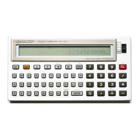
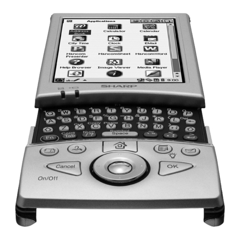
  9. Sharp PC-1500 Product manual

Sharp PC-1500 Product manual

All and more aboutSharp PC-1500
at
http:/lwww.PC-1500.info
Do
not
sell this PDF !!!
All and more about Sharp
PC
-1
500
at http:/lwww.PC-
150
0.info
FOREWORD
Since the release
of
the
PC
-1
500 on market, we have had great
numb
er
of
qu
estions from users regardingthe machine language
of
the
PC
-1500.
lro
meet with such demand from
arden
t users, we are now
se
nding t
hi
s text for study
of
the
ma
chine language ofthe
Sha
rp's
original design LH580I Microprocessor
and
LH58I I Periphera1
Cont
rol LSI
in
concern with the PC-1500 syste
m.
Because the
text
is
edited on the basis of user questions. it
ma
y not support
quality as a gui
debook
. In such
an
event, you are suggested
to
mak
e reference to micro
pr
ocessor guidebooks
pub
lished
on
market, in addition to this text.
You
r
op
inions
and
quest
ion
s are welcome
throu
gh
our
products
distributo
r.
NOTE: Machine lang
ua
ge
program.
wh
ich controls
ha
rdware di
rect
ly.
gives
yo
u more
va
r
io
us
fun
ctions than BASIC programs. However. you
sho
uld
check your mach
ine
langua
ge
progr·am enough w make no error
before executing it because
si
ngle wrong key operation may
ups
et the
program or occasionally make t
he
machine break down.
Sha
rp Corporation assum
es
no
liability
or
responsibil
it
y
of
an
y ki
nd
arising from
th
e u
se
of programs
or
program mater
ia
ls
or
any part
thereof.
SPECIAL NOTICE
TO
PC-1500A CUSTOMERS
Because
rh
c P
C-
I
500A
provides
rn
orc R
AM
than
th
e
PC-
1
500
.sornc
of
the
d
escr
ipt
ions
of
the
CHIP S
ELECT
SIG
NAIL.
ME
MORY MAP.
and
40-
PIN CONNECTOR (for memory modules)
require
mo
di
fica
ti
ons to suit
1he PC-1
500A
.
A summary of the di
fferen
c
es
between
1hc
PC-
I500A
and
the
PC
1
500
is
given in lhc a
dd
e
ndu
m
on
t
he
page
161.
Take notice of these differe
nc
es
when
us
in
g machine langua
ge.
Do
not sell this PDF !!!
All and more about Sharp PC
-1
500 at http:/lwww.PC-1500.info
CONTENTS
1.
Machine
Language .. . .. . .. . . . .. . .. .. . . .. . .. . .. .. . . . . .. .. . . . . .. . .. . . . . . . . .. . .. .. .•. . .. 1
2. LH5
801
Microprocessor
....................
.•
..
. : .. . . . . .. . . . .. . . .. . . . . . . .. . .. . .. .. . . . 5
2-1.
Outline
of
LH5801 .
..
. •
..
.
..
• .. .
..
.. .
..
.•. .
..
•
..
..
.
..
.
..
•
..
.. . . . . •.
..
. .•
..
. .. . . . . 6
2-2.
Internal
structure
. .. .. . .. . . . •. . .. ••. . . .. •. .. . •. . . .. .. . . . . •. . .. .. . •. . . . .. . . .. . . . . . 7
2-2-1. Bl
ock
diagram
. . . .. . . .. . . .. •.. . . . •. . .. .. . . . .. .. .. •• .. . . . ..•. . . .. •. . . . •. . . . 7
2-2-2. I
nterna
l registers . . .. . •. . . . •. . . ..•. . .. . . . . ..•. . .. . •. . . . • .. . .. . .. . . . .. .. . . . 8
2-2-3. Status flags . . .. . . . .. . .. . . . .. . . .. •. . . . •. . . ... . . .. .•. . .. . . . •. . . ..•. . .. . . . . . 8
2-2-4. CPU
pin
description
. . .. .. . •. . .. .•. . .. •. . . . . •. . ..••. . .. . . ••. . . .. . . . . .. . . . . 9
2-3.
Funct
ions . . .. . . . . .. . .. . . . .. . .. .. .. . . . . .. . . .. . . . . ..•. . .. . . . . .. .. . . . . . ... . . . .. . . . .
14
2-3-1. Ti
mer
......................................
...........
........
.. . .
..
.
....
14
2-3-2.
Interrupt
s . .. . .. . .. . . . .. . .. . . . . .. . . . .. . •. . .. .. . .. . .. . . . .. . . .. . . . •. . .. . .. . . 17
2-3-3.
2-3-4.
2-3-5.
Reset . . .. . .. .. . . . . .. . .. . . . . .. . .. . . . .. . . . . .. .. . . . . .. . .. .. . . .. . . . .. .. . . . . . . 20
CPU system s
eq
ue
nce .. . .. •. . . . . •. . .. .. . . . . .. . . . . .. .. . . . . •. . .. .•. .. . •. . . .
21
BF
flipflop
.. . .. . .. . . . .. . .. . . . . .. .. . . . .. . . .. •. . . . . .. . .. . . . . .. .. . . . . .. . .. . .
22
2-3-6.
WAIT
funct
i
on
........•.
. .
..
• .
..
. ..
.. ..
•. . .. •
.....
•
..
.....
••
. . .. •.
..
. .. . .
23
2-4. LH5801
instructions
...
.. .. . .. •.. .. . ••. .. •.. . . . .. . . .. •. . . . ••. .. . .. . •. . .. . .. .. .. . . .
24
2-4-1.
Outline
. .. . . . .. . . . . .. .. . . . . .. . . .. . . . .. . .. . . •. . . ..•. . .. . . . •. . . .. .. . . . ••. . . 24
2-4-2.
Ad
d,
subtract
,
and
logical
in
structions
.. . .. . .. . . . .. ••. .. . .. . •. . . . .. . .. . •. . .
25
2-4-3
. C
ompare
and
bit
test . .. . . . . . .. . . . .. . .. . . . .. . .. . . . • .. .. . .. . . . . .. .. . . . .. . . .
31
2-
4-4
. Transfer
and
s
earch
i
nstruct
ions .. .. . .. . . . . ..•. . .. • •. .. . .. . •. . . . .. . .. . • .. . 33
2-4-5
.
Block
transf
er
and
search
instructions
.. .. . .. . •. . .. ••. . . . .. . •. . . . .. . .. . •. . . 38
2-4-6. Rotate
and
shi
ft
in
str
uc
ti
ons
. .. .. . .. . . . .. . .. . . . .. . . .. . . . .. .•. . .. . . . .. .•. . .
39
2-4-7. CPU
control
ins
tru
cti
on
s.
..........................
.
..
. . .. •. . . . .. .
..
.. . . . . 42
2-4-8. J
ump
instruction
s . . .. . .. . . . .. . .. . . . .. . . . . .. . .. . . . .. . .. . . . .. . .. . .. . .. . . . . . 45
2-4-9.
Subrout
ine
jump
ins
tructions
. .. .. .. . . . . .. . .. . . . .. . . . . .. .. . . . . .. .•. . .. •. . . . 49
2-4-10. Return i
nstructions
. .. .. . .. . . . . .. .. . . . . •. . .. .. . .. . •. .. . . . . .. . .. . . . .. . . .. . . 53
2-
5.
Command
li
st
. . .. . . . .. . . . . .. .. . . . . .. . . .•. . .. . •. . . . •. . .. .•. . .. . . . •. . .. .•. .. . •. . . . 54
2-
6.
Electrical
characteristics
and
timings
.. . ..•. . .. • •. . ..•. . .. . . . .. . .. . •. . . . .. . .. . . . . . 63
3. LH5810/
LH58
11
1/0
port
controller
.. . .. •. . .. .. . . .. •. . . .••. . ..• .. .. . . . ••. . .. •. . . . .. . . 67
3-1.
Outline
. .. . ..
..
. .
..
..
....
..........•.......
. .
.•..
..
••.
.
..•..
.....
•.
....
..
..
....
. . 68
3-2.
Functions
. .. .. . .. . . . .. . •. . .. .. . . .. •. . . . .. . . . . •. . .. .. . . . . •. . .. . .. . . . . ..•. . .. •. . . . 68
3-3.
Internal
structure
. . .. . . . .. . . . .. . . .. •. . . . .. . . .. .. . . .. •. . .. ••. .. . . . . •. . ..•. . .. . . . . . 70
3-3-1.
Block
diagram
...............................
..
...
..........
......
.
.......
70
3
-3-2
.
Internal
reg
is
ters .. . . . •. . ... •. .. . . . . ... . . . .. .. . . . . .. .. . . . ••. . . . ••. . . .. . . .. 70
3-
3-3
. Pin
descr
i
pti
on . . .. . .. .. . .. . .. . . . .. . .. . . . . .. . .. .. . .. . . . .. . .. . . . . .. . .. .. . .. 73
3-4.
Funct
ions .. . .. . .. . . . .. . .. . . . .. . .. . . . . .. .. . . . . .. . .. .. . .. . . . . .. .. . . . . .. . .. . . . .. . .. 74
3-4-1.
Operation
. .
..
......
.
....
.
..
.....
.. . .
..
..
.
..
.
.....
..
..........
..
.....
...
.. 74
3-4-2.
Wait
contro
l . . .. . .. . .. .. . . . . •. . . . • .. .. .. . . .. •. . .. ••. . .. . .. •. . . . ••. .. . . . . .. 75
3-
4-3
. Serial data
input
. .. . . . .. . . . .. . . .. . . . . ..•. . .. . . . .. .• .. .. . . . •. . .. .. . . . . .. . . . 76
3-4--4. Reset . .. . . . .. . .. . .. . . ••. . ..••. . ... . . . .. . . . .•. . . . . • .. .. . .. •. . . .. •. . . . •. . . . 77
3-5. Spec
if
icati
on
. .. . . . .. . . . . .. . .. . . . .. . .. . . . .. . .. . . . . .••. . ..••. . . . .. ••. . ... . . . . •. . . . 78
3-5-1.
1/0
port
controll
er
inpu
t/
output
circu
it
s . . . . . .. •. . .. ••. .. . . . ••. . ... . . .. •. . . . 78
3-5-2. Pad
layout
and
s
tructure
. . .. .. . . .. . . .. . .. . . . .. . .. . •. . . . . ..•. . . .. •. . . . •. . . .
79
3-5-3. Electrical
chara
cte
ris
tics . . . . . •. . ..•. .. . . •. . . . •. . .. .. . . . . .. .•. . .. . . . .. .. . . . 79
Do not sell this PDF !!!
All and more about Sharp PC
-1
500 at http:/lwww.PC-1500.
in
fo
4.
PC
-1500 hardware
description
. . .. .. . . .. . . . .. . .. . . . .. . .. . . . . .. . . . .. . .. . . . . .. . .. . . . .. .. 85
4-
1.
PC-1500 system
configuration
.........
........
..
................
.
.........
..
.
..
..
86
4-1-1.
Outline
.. . .. . .. . . . .. . .. . . . . .. .. . . .. .. . . . . .. .. . •. . . . .. . . .. .. . .. . . . . . . .. . .. 86
4-1-2.
Block
diagram.
....
.
..
.
..
..
...
......
..
. .
.....
.
............
.
....
..
...
. .. .
..
87
4-1·3. Power supplies (PC-1500, CE-150, CE-158, CE-159)
..
....
.
..
. .
..
....
. . .
..
.. 87
4-2. PC-1500. . . ..
.........
..........
. .
..
.
..
.
..
.
....
.
..
.
..
......
...
..
..
..
.
..
..........
89
4-
2·
1.
Outline
.
..
. .
..
.
..
. .
..........
.• .
..
. .
..
.
..
•.
. .. ..
.. ..
• .
....
, . . .. •. . .• . .. . .
89
4·2·2.
Block
diagram
. .. .. . .. . •. . .. • . . •.. . .. •. . . . •. . . ... . . . . . .. . .. •. . . . . •. .. . .. . 90
4-2·3.
Chip
select
circuit
. . .. . .. . .. . . . .. . .. . . . . ..•. . .. . . . . ..• .. .. . . . . .. .. . . • . .. . .
91
4-
2·4
. PC-1500 system
memory
map
.
....
........
..
....
..
....
..
...
...
.
..
.
...
.....
94
4-3.
Connector
signals
/LSI signals
.....
.........
.
....
.•..........•....•.....•.....
....
102
4-3·1.
40-pin
connector
............
.
......................................
......
102
4-3-2.
60-pin
connector
............
..........
.
...
..........
....
....
.
.......
.....
103
4-3·3
. LH5801
Microproc
essor
.............
...
...........................
........
104
4·3·4. 110 PC
....
. ..
..
...........
.•
.
...
.........
• .. ..
............•...
..
.....
....
105
4-4. Key
matrix
and
key code
chart
......
.
............•....•..
.
................
. . .
..
. . 109
5. PC-1500
soft
ware
....
.......
.
..
. .
..
.....
..
......
.. .
........
.
....
•
....
••
....
••
..
...
..
.
111
5.·1.
BASIC
command
related
PC
-1500
machine
language
. .
..•.
..
.
••
..
.
••
.
..
.•..
. .
..
.
..
112
5-1-1. NEW. . .. ..
..
..
..
....
..
....
. .. . .
..
.
..
....
.....
.
.•
....
•
•....
•.
...
..
. .
..
..
. . 112
5-1-2.
STATUS
.
..
.
....
...
...
..
......
••
...............
•..
..
•..
...
•
....
...
.......
112
5·1·3. PEEK ..
..
..
•. . ..
•..
...
••.
......•.
. ... . . .
..
....
•..
...
•.
....•.....•
. .
......
113
5-
1-4.
POKE
......•..............................•............
...
•.
....
•. .
......
113
5·1·5.
CALL
.
......
......................
..
. .
.................................
..
114
5-1-6. CSAVE M
......
.........
.......
............
..........
...
...........
......
114
5-1-7.
CLOAD
M
....
......................
....
...•..............................
114
5-2.
Internal
code
chart
......
...
.......
.
..
•
..
..
......•..
.. .
...............
...........
115
5·3.
Expression
of
variable
and
program
...
.
.......
.
..•..
.
.••....•.......
.......
. .
....
116
5-3-1. Expression
of
decimal
number
....
...
..
..
.
••
. .
.............
..
...••.
. .. . . .. 116
5-3-2. Expression
of
binary
number
......
...
•
....
••
..
..
•.
..
. .
•.
...
•
..
...
•
..
......
116
5-3-3. Expression
of
character
string
.....
..
...
..
. •
..
..
••
....
.
.....
•.
..
. .•. . . . .
...
116
5-3-4.
Structure
of
variable
name
..
.
..
. ..
..
.
.....•....••....••...••..
..
••.
....
...
117
5-3-5.
Structure
of
program
..................
..
. .
..
. ..
•....•........
...
.....
....
117
5-3-6.
Structure
of
reserve area
....
....
.
....
.
....
.•
....
•
......
..
.
..
..
.
..
.
...
.
....
118
5-4. System
subroutines
....................
.
...............
•
..........
•.
....
.
........
120
5-4-1.
Character
function
s
........•..•.
...........
.........................
....
. 122
5·4-2
.
Arithmetic
subroutines
.....................................•..............
127
5-4-3.
Comparison
.
..
.....
.. . .
...
.•.
..
....
. .
..
.............................
.....
128
5-4-4. Search
..
.
..
. .
..
...................
.
..
.
...
••
....
•.
..
......
••.
...
.•
.....
..
. 129
5-4-5.
Disp
lay
..
..
•
..
..
•..
...
•
...
...............
•.
. .
..
•
.....•....
•.
....
•.
...
.
..
.
131
5-4-6.
Printer
...
..
....
. •
..........
•
...
•.
...
•
...
.
••
..
..
•.
..
. .
..
...
•
..
...
•
..
.. . ... 135
5-4-7. Cassette tape
..
...
..
.......
..
.
..
.
....
.
..
. •
..
. .•, .
..
.
•.
..
..
..
..
. .
..
. .
..
. . . 138
5-4-8.
Caution
for
system
subroutine
call
141
6.
Machine
language
programming
examples
.....
.. .
..
...
•
..
..
•
.....
•
.....
.
..
.
...
. .
.....
143
6-1. B
inary
to
hexadecimal
conversion
.........
.. ..
....
•..
..
•
.....
•
............
. .
...
..
144
6-2.
Display
inversion
......
..............
.
....
...
. .
........
•.
............
.....
. .
.....
145
6-3
. Single
display
dot
left
shift
...........
:
........................................
...
146
6-4
. Single
display
dot
right
s
hift.
....
...
.....
..
.. .
.....
..............
..........
...
....
147
6-5
. Conversion
of
USING
format
expressed
numerical
data
into
cha
racter
string
.
....
.
..
148
6-6.
Power
off
that
does
not
activate
the
printer
upon
power
on
148
Do not sell this PDF !!!
All and more about Sharp PC-1500at http:/lwww.PC-1500.info
[REFERENCE]
1.
Determin
i
ng
printing
character
size
and
direction
...
.
...
.•
..
.
.•
...
.
..
......
.
•.
..
.
..
....
150
2. Restorati
on
of
array
and
two-character
variable.
...
....
.
..
...
..
..
.
..
.
..
.. .
..
..
..
....
. .. 150
3.
Knowing
the use
of
CE
-1
50.
.
....
. .
..
. .. .. .. .. .
..
..
.. .
...
. . ..
..
. . ... .
..
. . .. •.
...
150
4.
CMT
format
.
..
. ..
..
.
..
. .
..
. .. .. .
..
..
. ..
...
..
...
. ..
...
..
..
.
....
..
.•
.
...
•. . .. . . .
..
. . ..
151
5.
Circuit
diagram
. .. . . . ••. . . .. .. .. • .. . . . .. . .. .
..
.
....
..
..
. . .
..
.
....
.
..
.
..
...
•.
...
153
5-1. PC-1500
..
.
..
.
....
.
..
.. •
.. ..
••
....
•
...
. .. . . . ..
.....
. . . .. .
...
. .. . . . . •. . .
....
...
.
..
154
5-2. CE-150 .
..
.. ..
...
..
. .
..
. .
..
. •
..
. .
...
..
....
.
..
. .
..
..
..
. 155
5-
3.
CE-151 . .
...
.. .
......
....
..
. .
..
..
..
...
.
..
...
..
.
..
....
. .
..
. .
..
..
..
...
..
.
...
... . . 156
5-4.
CE-153.
..
.. .. . .. . . . .. .. . . . . •. . . .. .. . . .
....
... . . ..
..
. . .
..
...
.
..
.
..
. .. . . . . . ... . . 156
5-5. CE-155. .
..
. •
.. ..
•.
..
... .
..
. •
..
. .. •.
..
.
..
. . ... .
..
. .
..
. .
•.
.
..
.
..
. .. . .. . •
.....
. .
5-6. CE-158...
..
. .
..
..
........
..
.
..
.
..
. .
....
. .
5-7. CE-159. .
...
. . .. ..
..
.. .
..
..
. .. . . .
..
....
. .
.. ..
..
..
. .
..
..
•.
. . .. •
..
.. .
..
. •.
..
. •
..
.. .
[ADDENDUM]
157
158
159
Differences between the PC-1500A
and
the PC-1500
......
. .
..
..
•.
.
..
.
••
. .
..
•.
.•
.
...
.
..
.. 161
Do
not
sell this PDF !!!
All and more aboutSharp PC-
1500
at http:/lwww.PC-1500.info
Machine Language
Do notsell this PDF !!!
All and more aboutSharp PC-1500 at http:/lwww.PC-1500.info
1.
Machine language
2
There are
many
program languages f
or
each purpose. PC-1500,
for
ex
amp
le, is
designed to
carry
ou
t both BASIC and machine lan
guag
e.
BASIC is easy to use,
however, execution speed
is
slow.
On
the ot
her
hand, machine language is
diff
i
cult
to un
de
rstand
but
execution speed is fast
Usual
ly
, machine language pr
og
ram
wo
u
ld
be
writt
en with the assemble
language,
wh
ich consists of
mn
e
monic
cod
es, and then theassemble language
will
be
translated
into
machine language.
[EXAMPL
E]
DISPLAY REVERSE
PR
OG
RAM
I. Prepare t
he
program with assemble language consisting of mncmo
ni
c codes.
LD
l UH.
78
H l
r prepare for assig
nm
e
nt
of
the
fi
rst disrlay bufferadd
re
ss
.
L
DI
D
EC
L
OA
EA
i
STA
LOP
CPI
BCS
R
TN
UL.4DH
UH
u
FFH
u
06H
UH.
77
11
OEH
advance the address
lake
da
ta
in
the accumulat
or
la
ke
the cornrlement
return data into memory
ma
ke the loop
return to RASIC
2. Trans
la
te
the above program into
ma
ch
i
ne
language. 1 h
t:
<
•
s~crn
blcr
tran
sl
atcs thc
assem
bl
e language
in
to t
he
machine
la
ng
ua
ge
au
t
om
atical
ly
acco
rd
ing 10 t
he
lis
t.
Hnweve
r.
a s
hort
program
ca
n be translatcd manuall
y.
(ha
nd
a
sse
mb
le
)
The abo
ve
program can be 1ransla1cd as
follows
:
68
78
6A
40
FD
62
25
BD
FF
2E
88
06 6C
77
93
Of"
91\
Do
not
sell this PDF
!!!
All and
mor
e about Sharp PC
-1
500at http:
/f
www.PC-1500.info
3. After the completi
on
of
the machine language program. write it in PC-1500 by using
POKE
instruction. And execute the
program
together with
BASIC
by
CALL
instruction.
Execute the following program.
You
ca
n ru'n
th
e BASIC
program
wi
th
~
161
and
the
machine language program with
CfilJ
(!2l
. Display reverse in machine language program
is faster
th
an
that
of
BASIC. You would know how functi
ona
l the machine language
pro
gram
is
.
EX.
Write the following program after executing NEW &4100
IEM<A
I .
10
11
A11
WA
IT
0
20
PRI NT
11
s ha
rp
pocke
t c ompu
te
r
11
~
FOR A= O
TO
155
40
GCU
RS
OR
A
50
GP
RIN
T
25
5-P
O INT A
60
NEX
T A
70 GO
TO
30
80
E
ND
100
II
B
II
WA
IT 0
11
0 PRI
NT
11sha
rp
p
oc
ke t
comP
u t er11
l
~
POKE &
40
C5
•
&68
•&
78
•&
6A
•&40•
&
FD
•
&6
2 · &25 ·
&B
D
·&
FF
·&2E·&
88
· &06
l~
POKE
&4
0 0 1
•&
6C •&77
•&
93
·&0E •&9A
140
CA
LL
&4
0C5
150
W
AI
T 20:PRI
NT
:G
OT
O 140
1
60
E
ND
This manual is div
id
ed into three
major
secti
ons
:
de
scription
of
LSI
(pp
. 5""8
4:
LH5801
Mi
croproc
essor & LH 5810/ I H58 I I 1/ 0 port
cont
roller).
PC
-
1500
hardwar
e de
sc
ription
(pp.
85
~
!09).
and
PC-1500 software
de
scripti
on
(pp.
1
11
~
141)
.
If y
ou
want to know
about
PC-1500 system
fi
rst. read from p.
K6
.
Do
not sell this PDF !!! 3
All and more about Sharp PC
-1
500at http:/lwww.PC-1500.info
4 Do
not
sell this PDF !!!
All and more about Sharp PC
-1
500at http:/lwww.PC-1500.info
LH5801
Microprocessor
Do
not sell this PDF !!! 5
All and more about Sharp PC-1500
at
http:
/l
www.PC-1500.info
2-1. Outline of LH5801
6
The
LH
5
801
Microprocessor is a CMOS static 8-
bit
microprocessor that
fea
tur
es
low
pow
er
di
ssipati
on
performance inherent to CMOS
LSI
and lar
ge
ca
pa
ci
ty
dat<J
processi
ng.
No
t o
nl
y that.
it
enabl
es
to
lO
configure a v
arie1
y
of
xys
tc
rn
s
wit
h a
few
additio
nal
ch
ip
s b
eca
us
e such as the LCD backplate sig
na
lgenerator. input port. external
latch cloc
k.
and
ti
mer are
bui
lt
in the
1.H580
1.
Features of the LH5801
CD
8-bit parallel
da
ta proc
essi
ng
CD
Direct accessing
of
I
28K
byt
es
CD
Use
of
a 6-bytc general purpose
regis
ter.
in
addi
ti
on
t0
the accumulator. allows to
comp
ri
se
thr
ee
pairs
of
2-byte date pointers.
© 9-bit timer
ca
pabi
li
ty
©
Th
ree kinds
of
i
nt
errupts
• Non-maskable i
nt
errupt
• Mas
k.
ab
le interrupt
•
Ti
mer interrupt
©
82
instruction
set
CD
WAIT
fu
nction (memory access control poss
ib
le)
© Clock
Pcb
for input por1
(8-
bi
1)
and external
lat
ch
CV
Memory backup functi
on
(BF
!.
BF
O)
® LCD backplate signal control
@
Exu
ernal crystal connection for clock generation
@ Re
du
cing program steps by means
of
28
-k
ind sin
gle
step
ve
ctor subroutine jump
Do
not
sell this PDF !!!
All and more about Sharp PC
-1
500at http:/lwww.PC-1500.info
2-2.
Internal
Structure
2-2-1. Block diagram
Fig. 1-1 Block diagram
of
LH5
801
0
AOO-AD
7
XLO
X
Ll
<t>
DS
WAIT
HA NMI Ml
VGC
vcc
vss
s
x
re
g
v
1eg
u
reg
T A
lnst
rvct.on
decoder
&.
CP
U
con
tr
ol
LC
D
t()-H7
bac
k
plale
VA
4
VB
po
wor
VM
su~ly
con
tr
ot
VDIS
PU
PV
DISP
OPf
S
AK
8R
Q
RESE
T
OD
R; W ME
0M
E1
8f
0 8
FI
00-07
IN0-
IN
7
PU
PV
DISP
Fig. 1-2 Internal register & flipflops
'
PH
'I Pl .,
P:
P
r
~ram
c
ou
n
te
r
r
SH
'I SL .,S: S1
ack
poi
nter
XH •
XL
8 Xregf
Data
pointer
.
YH
•
Yl
8 Yreg : or
t-
UH
• UL 8 Ureg general purpose
1e91ste
r
A
~
A: Accumulator
TM .,
TM
:
Tu
ne
r
L
'1
PU
f : GeneraI purpose flipfl
op
LJ
PV
L'.J
DISP: L
CDon
/off
co
nt1ol
Do
not sell this PDF !!!
•
0 'o oIH v z 1E c
r·.
s
latus
r
e~
1
s
t
e
r
- C:
Ca
rry
and
borrow
(byte to byte)
-I
E:
Int
err
up
t enable
- Z: Zero
V: Overf
lo
w
H:
Carry
(
d1
g1n to
d1~1
t
)
7
8
All and more about Sharp PC-1500at http:/lwww.PC-1500.info
2-2-2. Internal registers
Symbol Name
Bit
size Descripti
on
p Program
co
unter 16 Indic
ate
s the
add
ress next to t
he
addr
ess t
he
CPU
is
now
in
execut
i
on
It will
be
i
ncr
emented
by
'"I"
VJhe
n the n
ext
inst
ruc
tion is f
etc
hed.
s Stack 16 Indicates the stack address.
p
oi
nte
r
A A
cc
u
mu
l
ator
8
Used
for
reten
ti
on
of
operat
iona
l
res
ult
or
for
data
tra
ns
fer
\V
it
h the
ex
ter
n<JI
memo
ry.
XL 8 XL, XH. YL.YH,UL. UH
compr
ise independent 8·
Xr
eg
XH
8
bit
registers.
Also.
1..1s
ed
as
16-bit
da
ta
poin
t
er
s. Xreg. Yreg.
and
YL 8
Ur
eg.
v1
he
n used
in
a
pair
.
Yr
eg
YH Data register 8
UL
8
Ur
cg
UH
8
TM T
imer
co
un
ter 9 When "
O'
' is set
to
the TM. it
stops
the
co
unte
r
act
i
on
.
Whe
n
anyth
i
ng
other
t
ha
n
"O
..
is set. it
puts
the
cou
nt
er
into a
ction
.
\A
1
he
n
the
TM
t
urns
f
ull
of
..
,
..
v1
ith !
he
int
er
r
up
t e
nabl
e s
igna
l IE on.
C
PU
ex
ecu
t
es
an
in
terr
up
t
processing
.
PU
1 General purpose
fl
ip
-
flo
p.
PV 1
OISP 1
LCD
on
/off
co
ntr
ol.
T
St
at
us
regist
er
8
Lo
w
order
5 bits re
pr
esent one
of
five status
of
oper
at
ional r
es
ul
t.
2-2-3. Status flags
Status !lags.
C.
V.
H. Z. IE
ar
c contai
ne
d
in
the 8-bit s
ta
cus
register.
In
general.
!l
ags nther
than IE change their state
af
ter the exec
uti
on
of
arithmetical instruction.
Status re
gister
T
=I
0 IOI0 IHIVIZ I1EjCI
Q)
C
arry
flag
C
Ca
rr
y
fl
ag C is set
wh
en there
is
a carry from the MSBand r
eset
whem
there is no carry.
For
SUBTRACT.
th
e !lag is set when there is no borrow or
re
set
whe
n t
he
re
is.
@
Half
c
arry
flag
H
Ha
lf carry
fl
ag
H
is
set w
hen
th
ere is a carry from the b
it
position
'"3"
(d
ig
it
-to-di
gi
t
can
y) and
re
se
t
whe
n the
re
is
no
carry.
(j)
Zero
flag Z
Ze
ro !lag Z is
set
wh
en
the operational r
es
ult is zero and reset when not.
© Overflow flag V
Qv,er
flo
w !lag Vis set
or
reset dependi
ng
on t
he
operationalr
es
ult
of"C
6E
l:1
Cr;
where.
th
e carry from
th
e bit po
si
tion 6
of
a
si
ngle byte data is assumed to
be
( 6a
nd
thecarry
from the bit p
os
it
ion 7 to
be
C7
Single byte
da
ta
I I I I I I I I ]
87
86
85
84
8382
8 1BO
Do
not
sell this PDF !!!

All
and more about Sharp
PC
-1
500
at http:/lwww.PC-1500.info
2-2-4. CPU pin description
U'
)
..:::J"('f')('\1.-.0
u
oooooo8
g~~8~8o~~o8
Z<~<<~<<><~<<<<<<<<
R/ W
57
56
55
54
53
52
51
50
49
48
47
46 45 44
43 42
41
40
39
~ ~ 07
P4>
59
37
D6
PV
60
36
05
PU 61
35
D4
4>0S
62
34
03
XLO
63
33
02
XU
64
32
01
WAIT
65
31
00
IN7
66
L
H580
1
30
MEO
I
N6
67
29
ME
l
I
N5
68
(T
OP
VIEW)
28
OD
I
N4
69
27
HO
IN3
70
26
Hl
I
N2
71
25
H2
INl
72
24
H3
I
NO
73
23
H4
NC 74 22
H5
NC
75
21
H6
NC
76
20
H7
1 2 3 4 5 6 7 8 9 10
II
12 13 14
15
16
17
18 19
.....
UJ
lfJ
o
_
e>
ou..~ue>
!:Q
-
w
u~~~
~
~c
u~~oc~~-
1
~c~
~ z
mm>mom>>>>>>Z~xxo
Q)
XLO,
XL1
These
arc
externalcrystalconnection pins.
XLO
is the input pin
and
XLI
is the
output
pin. Clock frequency is divided by two inside the CPU. When t
he
2.6M
Hz
crystal
is
co
nnected, the C
PU
opera
tes ·
under
I.3M Hz
of
internal machine cycle.
(j)
ADO ~
AD
1
5
Address
bu
s.
Outputs
from these pins
arc
3-statc (three output states
of
high, low and
high impedance) and
go
high impedance with
BRQ
(Bus ReQuest). Basica
ll
y,
64K
bytes
of
memory
area
is s
uppo
rted for direct
acc
essing,
but
it is
made
possible toaccess
e
ve
n 128K
area
of memory
area
when MEO
and
M
El
arc
used.
Q)
0
0
~
0
7
Bidirectional
da
ta
bu
s which is used to write
or
da
ta to/ from
the
external m
emo
r
y.
©
MEO
,
ME
1
Memory
enable signals.
As
mem
ory
area
of
64K bytes is accessed by MEOa nd
ano
th
er
64K bytes by
ME
I, it permits direct access
of
memor
y
area
of
1
28
K bytes in total.
Si
nc
e
MEO
is used for instructi
on
fetch
and
sta
ck
ope
ra
ti
on, accessing by m
eans
o'f the
program counter P
and
stack pointer S is limited to a maximum of 64K bytes.
As
for
data
acce
ss
ing,
both
memory
area
s covered by M
EO
and ME I
ca
n be
con
trolled
by a CPU in
st
ru
ctio
n.
9
Do
not sell this PDF
!!
!
10
All and more about Sharp PC-1500at http:/lwww.PC-1500.info
CD
4JOS
Through
this
lin
e can be supp
li
ed the clock to
an
external system since the clock in the
same
pha
se
as
the
CPU
internal basic clock is on this lin
e.
Co
nnection of the 2.6M Hz
crystal oscillator
to
XLO
and
XLI
wi
ll s
upp
ly the
cl
ock
of
I.3MHz.
©RIW
M
emory
write signa
l.
A low on this
li
ne causes the
CPU
to send
data
on
the
da
ta bus.
0
00
Outpu
t disable signa
l.
/\
high on this line causes the CPU
to
prohibit
data
out
put to the
externa
l
de
vice.
It
is used in w
ri
t
in
g
data
to the m
emo
ry.
<l>OS
M
EO
or
M
£1
1
R/W I
OD~
~
A
~-
-
-~
--'
/
00
~0
7
_..
----
--<
(
MEMORY
DATA
:
)
---
--
~<
\_
__
cP
_u_o_AT_A_
.,_.;)---
--
- -
Memory read cycle Memory wrrto cy
cle
©RESET
CPU
reset input. Hi
gh
state
of
this sig
na
l resets the
CPU
and
the c
on
tents
of
the
addr
ess
FFFEH
is set to the register PH
and
the contents
of
the
add
ress
FFFFH
to the
register PL.
Wh
en it
turn
s
fr
om
high to low leve
l.
it star
ts
pro
gra
m executi
on
from the
ad
dress
of
the
pro
g
ram
counter.
@ NMI
Non
-maskablc interrupt input. High state
of
this signalcauses i
ntermp
t to the
CP
U, to
whi.ch the
CPU
unconditionally responds
and
starts the interrupt
proc
essing routine
of
whi.ch h
ig
h ord
er
byte address is r
ep
resented by the
add
ress
FFFCH
and
low order
byte
add
ress by
FFFD
H.
Do
not
sell this PDF !!!
All
and more about Sharp
PC
-1
500
at http:/lwww.PC-1500.info
@
Ml
Mask
ab
le interr
upt
input. When the inter
rupt
enable
fl
ag IE is
act
i
ve
. a high on the pin
Ml
requests in
terrup
t, to which the
CPU
starts to execute the interr
up
t
pr
ocessing
rou
tine whose
hi
gh
or
de
r byte
add
ress is represented
by
the address
FFF8
H and l
ow
order
byte
add
ress by
FFF9H
.
How
instruction execution address is determined against the reset
and
interrupt
input
Addr
ess
EOO
OH
El
71
H
E22B
H
E22CH
fffBH
9
A
B
c
D
£
FFFFH
External
memory
....--
~
-
-
~
-
::.----..::
-
1--1
-
El
H I
71H r
E2H f
2CH
E2H
f
28H
EOH l
OOH
Do
not sell this PDF !!!
-
-..
Staft
addn
.
~ss
by
RESET inp
ut
Start
add
ress
by
Ml input
Start address
by NMI i
npu
t
Start
add
re
ss
by
ti
me
r interrupt
11
12
All and more about Sharp PC
-1
500at http:/lwww.PC-1500.info
@BRO
Bu
s
re
quest s
igna
l.
@BAK
Bu
s.
request ackow
led
ge
signa
l.
When BRQ go
es
high, the CPU
is
sues a h
ig
h
le
ve
l of
signal
on
BAK
in
response
10
i
t.
The CPU keeps addre
ss
bus
(ADO
~
i\D
15),
data
bu
s
(DO
~
D7)
.
MEO
, MEL R/ W, and OD h
igh
impedance when
BAK
is
in
hi
gh
leve
l.
@OPF
Op
er
ation
code
fetch signal w
hi
ch is sent out
whe
n CPU fetches oper
at
i
on
co
de
(instructi
on
code).
OPF
is
issued only when operation code
is
fetched and
will
not be i
ss
ued in
fe
tching
address data. immediate data. and second byte of the two-step instruct
ion
.
<l>OS
ADO
-
AD15
M
EO
OPF
@
INO
~
IN7
'
'
-,-
..
-----
--
,
I I
~-
--~
-
I
La
st
cy
cle
__,
_
__
Operati
on
code
__
__,
fetch
Input port through which the CPUreceives 8-hitdata intotheaccumulato
r.
As
internal
pu
ll
up
re
sistor is used. the CPU assumes
it
to be
high
l
evel
wh
en
not connec
te
d.
@>
p
qj
External latch clock. With h
ig
h l
eve
l of this clock. the contents
of
the accumulator is
sent
on
the data bu
s.
Addition
of
IC
wi
ll
compri
se
an output port.
R
EFE
RENCE: ATP instruc
ti
on.
@PU,
PV
These arc CPU internal flipflop outputs.
PU
and
PY
ar
e
fu
rnished with set and
rese
t
instructions.
Do
not
sell this PDF !!!
All and more aboutSharp PC-1500at http:/lwww.PC-1500.info
@
WAIT
CPU
wait signa
l.
A high
on
this line
\top~
the
clock
<P
so
1ha1
th
e C PU halts its
operation.
/\s
soon
as
WAIT
rnrns
lo\\.
the
CP
U resumes
the
operation
.
Basic clock
Cloc
k
WAIT
np1
1op
WA
<POS
NOTE
:
WA
is
l
he
flipfl
op
dedica
t
ed
10 WA
IT
,
by
wh
ic
h the
WA
IT i
np
ut is received
at
the
falhng
edge
of
the cl
ock
<!>O
S Because the CPU
operating
clock
<P
stops
whe
n W/\1sh
ig
h,
ii
makes the CPU
.stopp
ed,
conseque
ntly.
@ HO
...,
H7
I.
CD bac
kp
late si
gna
l
ou
1pu1.
/\s
the liquid cr
ys
ta
l displ
ay
(LCD) is
dr
iven by
backp
l
ate
signals
and
segme111
~igna
l
s.
the
CPU
co
ntr
ols the
ba
c
kp
late signals.
@VA, VB, VM, VDIS
I.CD
backplate
pow
er
sup
pl) input>.
®
HIN
Input
signal
to
th
e
cou
nt
er
from
which
the
L
CD
backplate
signab
11
0-
11
7
arc
genera
ted . orrnally.
connec
ted
to
pin
ll
A
of
the
CPU.
@
HA
CPU
in
1e
r
m1
Idivider
output
pin.
It
is u
se
d for· the basic
clock
that
dr
ives the
LCD
that
co
nn
cc1c
cl
w
it
h HIN and the segment signal gen
erating
LS
I.
@
DISP
I.
CD
on/
off
control
signal ntllpul which can be set or reset by m
ea
ns of instru
ct
ion.
@ BFO, BFI
RF
nipflop
output
(
BFO
)
and
input
(
IJ
FI). The
BF
nipllop
is
n:..,.ct
by
th
e
OFF
instruction
from
the
CPU.
and
''ill
be~•
when the
input
BF!
is
turned
to
high level.
BFO is in low level
wh
en
the
BF
flipflop is set
and
in high level when
rc~ct.
As
VGG
is
power
s
uppl
yto
the
BF
ni
pO
op.1
he
contents of
the
nipOop
arc
retained
a~
l
ong
as
VGG
is in
supply
.
'ormally. it
is
u
sed
fo
r
mem
ory
backup
system.
Do notsell this PDF !!!
13
All and more about Sharp PC
-1
500at http:/lwww.PC-1500.info
2-3. Functions
14
2-3-1. Timer
T
he
t
im
er
is
a 9-bit polynominal counte
r.
The counter
val
ue can be set by t
he
A
MO
or
AM
I instruction
(l
f t
he
CP
U.
Shown
in
"
POLI
NOM
I
NAL
COU
NTER"
is the
li
st of
hexadecimal data
of
counter
wit
h decimal count numbe
r.
TI
1e timer operat
es
continuously at all
tim
es. When the count
er
va
l
ue
reaches I
FFH.
it
iss
u
es
interrupt requ
es
t
rn
t
he
CPU. If IE (Interrupt Enab
le)
nagis active at that point.the
CPU
jump
s to
th
e timer i
nt
errupt processing routine
who
se
high
order b
yte
address
is
re
presented by the contents
of
the address
FFFAH
and low order byte address by t
he
contents
of
the address
FFF
BH
. The ti
mer
has to be
se
t to
OOOH
when it is not
use
d.
Since it counts
in
syn
ch
ronization wi
th th
e
cl
ock
<1>
F,each one cy
cle
of
<1>
F
in
crements the
counter o
ne
step.
Oscillator
'--~D
~
i
v
_
id
_
e
r
~__,
~
<1>
F
Wh
en the 4MHz crystal osci
llat
or is
in
connectio
n.
th
e timer
is
incremented
at
each
32~1s
ec
.
bccause
(!>
F
is
3I.
25k
Hz.
Do
not
sell this PDF !!!

Other manuals for PC-1500

4

Other Sharp PDA manuals

Sharp Zaurus SL-5500 User manual

Sharp

Sharp Zaurus SL-5500 User manual

Sharp PC-E500S User manual

Sharp

Sharp PC-E500S User manual

Sharp Zaurus SL-5500 Quick start guide

Sharp

Sharp Zaurus SL-5500 Quick start guide

Sharp Zaurus SL-5500 User guide

Sharp

Sharp Zaurus SL-5500 User guide

Sharp TM-20 User manual

Sharp

Sharp TM-20 User manual

Sharp Zaurus SL-5500 User manual

Sharp

Sharp Zaurus SL-5500 User manual

Sharp Zaurus SL-5500 User manual

Sharp

Sharp Zaurus SL-5500 User manual

Sharp PC-1600 User manual

Sharp

Sharp PC-1600 User manual

Sharp YO-P20H User manual

Sharp

Sharp YO-P20H User manual

Sharp PC-1246S; PC-1248 User manual

Sharp

Sharp PC-1246S; PC-1248 User manual

Sharp PC-E500 User manual

Sharp

Sharp PC-E500 User manual

Sharp PC-1350 User manual

Sharp

Sharp PC-1350 User manual

Sharp PC-1285 Assembly instructions

Sharp

Sharp PC-1285 Assembly instructions

Sharp EL-6053 User manual

Sharp

Sharp EL-6053 User manual

Sharp PC-1246 User manual

Sharp

Sharp PC-1246 User manual

Sharp SL-C750 User manual

Sharp

Sharp SL-C750 User manual

Sharp SL-6000L User manual

Sharp

Sharp SL-6000L User manual

Sharp PC-1500 User manual

Sharp

Sharp PC-1500 User manual

Sharp PC-1251 User manual

Sharp

Sharp PC-1251 User manual

Sharp SL-C1000 User manual

Sharp

Sharp SL-C1000 User manual

Sharp PC-1403 User manual

Sharp

Sharp PC-1403 User manual

Sharp PC-1500 User manual

Sharp

Sharp PC-1500 User manual

Sharp Zaurus SL-5500 User manual

Sharp

Sharp Zaurus SL-5500 User manual

Sharp TM-20 Quick start guide

Sharp

Sharp TM-20 Quick start guide

Popular PDA manuals by other brands

Blackbe;rry BlackBerry Wireless Handheld user guide

Blackbe;rry

Blackbe;rry BlackBerry Wireless Handheld user guide

Point Mobile PM95 user manual

Point Mobile

Point Mobile PM95 user manual

Winmate E430 Series user guide

Winmate

Winmate E430 Series user guide

Franklin bes-2110 user manual

Franklin

Franklin bes-2110 user manual

Honeywell ScanPal EDA5S user guide

Honeywell

Honeywell ScanPal EDA5S user guide

Coppernic Access Quick Start and Regulatory Guide

Coppernic

Coppernic Access Quick Start and Regulatory Guide

Rolodex Rolodex RF-384 Bedienungsanleitung

Rolodex

Rolodex Rolodex RF-384 Bedienungsanleitung

Casio DT-900 Operation manual

Casio

Casio DT-900 Operation manual

Opticon H-19 manual

Opticon

Opticon H-19 manual

Melco Advantage 18 Operation manual

Melco

Melco Advantage 18 Operation manual

BitaTek Frey Glider XS quick start guide

BitaTek

BitaTek Frey Glider XS quick start guide

CipherLab RK25 Reference manual

CipherLab

CipherLab RK25 Reference manual

Clip Sonic PD153 instruction manual

Clip Sonic

Clip Sonic PD153 instruction manual

Point Mobile PM250 user manual

Point Mobile

Point Mobile PM250 user manual

Comtech EF Data SMS400 user guide

Comtech EF Data

Comtech EF Data SMS400 user guide

Unitech PA600 Specifications

Unitech

Unitech PA600 Specifications

SPOT SPOT X quick start guide

SPOT

SPOT SPOT X quick start guide

Intermec PEN*KEY 6400 Programmer's reference guide

Intermec

Intermec PEN*KEY 6400 Programmer's reference guide

manuals.online logo
manuals.online logoBrands
  • About & Mission
  • Contact us
  • Privacy Policy
  • Terms and Conditions

Copyright 2025 Manuals.Online. All Rights Reserved.