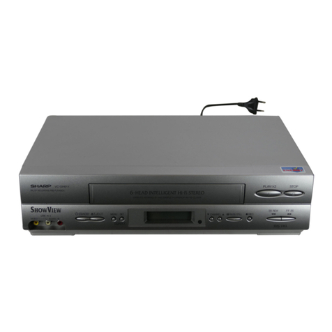
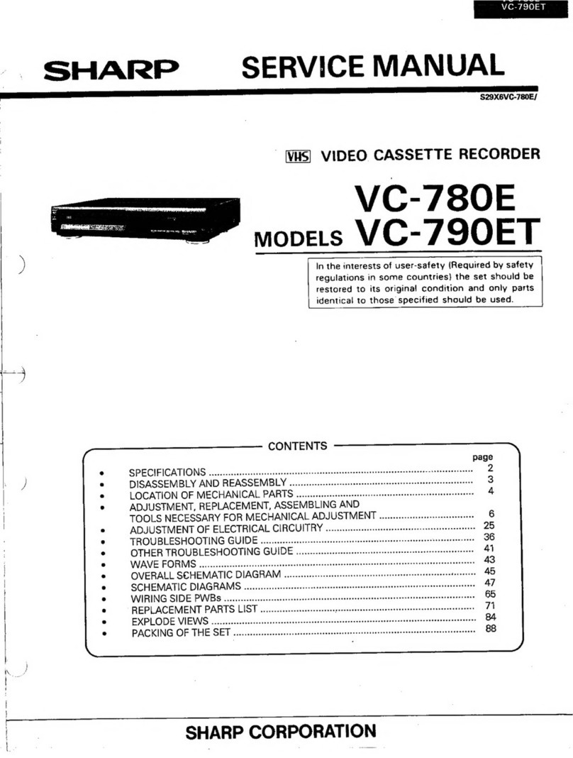
Sharp VC-MH80 User manual

VC-M
H80
VC-M
H90
SHA@l=
SERVICE
MANUAL
I
S04FZVC-MH80l
lvusi
VIDEO
CASSEITE
RECORDER
VC-MH80
MODELS
VC-MH90
In
the
interests
of
user-safety
(Required by
safety
regu-
lations
in
some
countries)
the
set
should
be
restored
CONTENTS
Page
1
.
SPECIFICATIONS .._........_.........................................._..............._...........................
3
2.
DISASSEMBLY
AND
REASSEMBLY
.
.
.
.
.
.
.
.
.
.
.
.
.
.
.
.
.
.
.
.
.
.
.
.
.
.
.
.
.
.
.
.
.
.
.
.
.
.
.
.
.
.
.
.
.
.
.
.
.
.
.
.
.
.
.
.
.
.
.
.
.
.
.
.
.
.
.
.
4
3.
FUNCTION OF MAJOR
MECHANICAL
PARTS
.
.
.
.
.
.
.
.._..........................................
8
4,
ADJUSTMENT, REPLACEMENT
AND
ASSEMBLY
OF
MECHANICAL
UNITS
.
.
.
.
10
5.
ELECTRICAL
ADJUSTMENT
.
.
.
.
.
.
.
.
.
.
.
.
.
.
.
.
.
.
.
.
.
.
.
.
.
.._................................_.........._........
34
6.
MECHANISM OPERATION
FLOW
CHART
AND
TROUBLESHOOTING GUIDE
.
43
7.
TROUBLESHOOTING
.
.
.
.
.
.
.
.
.
.
.
.
.
.
.
.
.
.
.
.
.
.
.
.
.
.
.
.
.
.
.
.
.
.
.
.
.
.
.
.
.
.
.
.
.
.
.
.
.
.
.
.
.
.
.
.
.
.
.
.
.
.
.
.
.
.
.
.
.
.
.
.
.
.
.
.
.
.
.
.
.
.
.
.
.
.
.
.
.
.
.
49;
8.
BLOCK DIAGRAMS
.
.
.
.
.
.
.
.
.
.
.
.
.._......._..._..................._.._......_...._........................._.._....
67
9.
CIRCUIT
DIARAM
AND
PWB
FOIL PATTERN
.
.
.
.
.
.
.
.
.
.
.
.
.
.
.
.
.
.
.
.
.
.
.
.
.
.
.
.
.
.
.
.
.
.
.
.
.
.
.
.
.
.
.
.
.
.
.
.
.
.
.
.
.
.
75
10.
REPLACEMENT
PARTS
LIST
.
.
.
.
.
.
.
.
.
.
.
.
.
.
.
.
.
.
.
.
.
.
.
.
.
.
.
.
.
.
.
.
.
.
.
.
.
.
.
.
.
.
.
.
.
.
.
.
.
.
.
.
.
.
.
.
.
.
.
.
.
.
.
.
.
.
.
.
.
.
.
.
.
.
.
.
.
.
.
105
1
1
.
EXPLODED
VIEWS
.
.
.
.
.
.
..r........................................................._............................
127
12.
PACKING
OF
THE
SET
.
.
.
.
.
.
.
.
.
.
.
.
.
.
.
.
.
.
.
.
.
.._.................................................................
131
SHARP
CORPORATION

VC-MH80
VC-MH90
PRECAUTIONS IN PART REPLACEMENT
When servicing the
unit
with
power
on,
be
careful to the section
marked
white
all
over.
This
is
the
primary
power
circuit which
is
live.
When checking the soldering side in the tape travel mode, make sure first that the tape has
b;en
loaded and
then turn over the PWB with due care to the primacy power circuit.
Make readjustment, if needed after replacement of part, with the mechanism and its PWB in position in the
main frame.
(1) Start and end sensors: D710 and D709.
Insert the sensor’s projection deep into the upper hole of the holder
(LHLDZ1893AJOO).
Referring to the
PWB, fix the sensors tight enough.
(2) Photocoupler
RH-FX0005GEZZ:
IC901
Refer to the symbol on the PWB and the anode marking of the part.
(3) Cam switches A and
B
(RH-PX0231GEZZ)
:
D714 and
D713.
Adjust the notch of the part to the white marker of the symbol on the PWB. Do not allow a6y looseness.
(4) Take-up and supply sensors
(RH-PX0232GEZZ):
D712 and D711.
.
Be careful not to confuse the setting direction of the parts in reference to the symbols on the PWB. Do not
allow any looseness.
(5) Diode bridge (RH-DX0083GEZZ): D901.
Adjust the
+
marking of the pat-t to the
symbol’scathode
marking on the PWB.
2

VC-MH80
VC-M
H90
Format:
Videorecording.system:
Video signal:
Recording/playing time:
Tape width:
Tape speed:
Antenna:
Receiving channel:
RF converter output signal:
Power requirement:
Powerconsumption:
Operating temperature:
Storage temperature:
Weight:
Dimensions:
VIDEO
Input:
output:
S/N ratio:
Horizontal resolution:
AUDIO
Input:
output:
Hi-Fi dynamic range:
Normal S/N ratio:
Frequency
responce:
Accessories included:
1.
SPECIFICATIONS
VHS
PAlJSECAMlMESECAMINTSC
standard
(VCMH80)
VHS
PAL/MESECAM/NTSC
standard
(VGMH90)
Two rotary heads, helical scan system
PAL-ISECAMINTSC
colour and
B/C,I,
D/K, Msignals, 625 lines
240 min max. with SHARPE-120 tape (LP mode)
480 min max. with SHARP
E-240,tape
&P-mode)
480 min max. with SHARP
T-.160
tape
(EP.mode)
12.7mm
23.39 mm/s (PAL SP)
11.70
mm/s (PAL LP)
33.35
mm/s(NTSCSP)
16.68mm/s(NTSC
LP) 1
l.lZmm/s(NTSC
EP)
75 ohm unbalanced
VHF Channel
1A-520
UHF Channel
E21-US83
(VGMH80)
UHF Channel
E21-E69
(VGMH90)
VHF Channel
E30-E39
(preset to CH E39
(VGMH80)
or CH E36 (VC-MH90))
AC1
lo-24OV,
50160Hz
Approx. 20 WatAC220VI50Hz
(VC-MHSO)
Approx. 22W at
AC220V/50Hz
(VC-MH90)
5°C to 40°C
!
-
20”Cto60”C
j
Approx. 4.5 kg
430 mm (W)
x
340
mm(D)
x
96 mm (H)
0.5
-
2.0 Vp-p, 75 ohm
I
.O
Vp-p, 75 ohm
45
dB
(PAL SP)
250 lines (PAL SP)
0
dBs
=
0.775 Vrms
Line: -8
dBs,
47kohm
Line:
-
8
dBs,
1
k
ohm
85dB type
40dB
(Hi-Fi)
20Hz-20kHz
(Normal)
80Hz-5kHz
75 ohm coaxial cable
Operation manual
Infrared remote control
Battery
(2~~s.)
AC plug adaptor
(VC-MH90)
AV cable
of our policy of continuous
improvement,:we
reserve
to alter design and specifications without notice.
Note: The antenna must correspond to the new standard DIN 45325
(IEC
169
-
2) for combined UHF/VHF antenna with 75 ohm connector.

vc-ma0
VC-MH90
2. DISASSEMBLY AND REASSEMBLY
2-1
DISASSEMBLY OF MAJOR BLOCKS
TOP CABINET
:
Remove 4 screws
0.
OPERATION PWB
:
Disconnect the
FFC
from the
BOlTOM
PLATE
:
Remove 5 screws
8
and 2
screws
0.
socket
0.
Remove 2 clips
do,
.
OSD/MPX PWB
:
Disconnect the
FFCs
from the 3
FRONT PANEL
:
Remove 7 clips
@.
TIMER PWB
:
Remove 1 screw
8.
Disconnect sockets
0.
Take out 3 holders
the
FFC
,from the sockets
@
0.:
and
@
. Remove 3 clips
@.
TOP CABINET

VC-M
H80
VC-MH90
MECHANISM/
MAIN PWB
ASSEMBLY
:
Remove 2 screws
@,2
screws
@and
2 screws
@
.Remove
2
screws @from below the main
frame. Take out the socket,
@
Remove 2 screws
@
and take
out the tuner holder. Rempve
1 screw
@I.
Lift the antenna terminal block
and take the mechamism/main
PWB assembly out of the main
frame. Be careful not to hit the
REC TIP switch located below
the cassette controller.
TIfhER
PWB
&XM+APXPWB

VGMH80
VC47lH90
HEADAMPLIFIER
:
Remove
1
screw
@.
HQLDE+
ANTENN
A
:
Remove ‘1 screw
a.
MECHANISM
:
Disconnect the
FFCs
from 2
CHASSISI
sockets
@
.
CASSETTE
Disconnect the connectors
CONTROLLER
from 2 sockets
@.
Take the
ASSEMBLY
relay PWB out of the socket
@
Rmove 1 screw
@
and detach
the
head.amplifier
unit.
Disconnect the
FFC
from the
socket
@
. Remove 2 screws
@
from:behind the main PWB.
Lift the mechanism chassis/
cassette controller assembly
vertically to take it out of the
main PWB.
CASSETTE
CONTROLLER
:
Remove 2 screws
@.
CASSETTE
CONTROLLER
/
HEADAMPLIFIER
CHASSIS/CASSETTE
CONTROLLER
ASSEMBLY
-ANTENNA
TERMINAL BOX

VC-MH80
VC-MH90
2;2-
PRECAUTIONS IN-REASSEMBLING
MOUNTING THE CASSETTE CONTROLLER
Initial setting is indispensable
before placing the cassette controller in the mechanism. The initial
setting
is made in two ways; electrical and mechanical.
Electrical setting:
(1) Make a short-circuit between
TP5001
and TP5002
of the
TP
plug
(TPSOO*)
which is on the
timer
PWB.
(2) Plug in the AC
power
cord and make sure the mechanism is in the initial setting position
(*l)
.
(3) Unplug the
AC
power cord. Remove the above short-circuit.
NOTE: This method is used when the mechanism has been already set on its-PWB.
Cassette control
drive
gear
O/
Mechanical setting:
Turn the loading motor’s
pulley feed gear using a
screwdriver
and be sure
that the mechanism is
back to its initial setting
position
(*l).
Now place
Drive
angle
of
the cassette controller in
cassette control
position. (This method is
applicable for the
mechanism alone.)
Phase
matching
point
COUPLING
TH.E.MECHANISM
TO THE PWB
Match the mechanism’s projections with the two
symbots
(r&nd
reference and oval sub-reference) on the
main PWB. Place the mechanism straight-down in position with due care so that the mechanism chassis’s outer
edges should not damage any parts nearby.
Tighten up the two screws (one for fixing the mechanism and
th6
head amplifier shield, the other on the main
PWB’s
soldering side and located near the loading motor) to fix the mechanism and main PWB. Reconnect the
FFC
cables
(AG,
AD and ZA) and harnesses (AE and AL) between the mechanism and main PWB.
Parts to pay attention to:
Stat-t and end sensors
07
10, D709
Record tip switch
5701
Take special care of the MC-AC connector
(board to board) between the mechanism
and main PWB.

VC-MH80
VC-MH90
3:FUNCTlON
OF MAJOR MECHANICAL PARTS (TOP VIEW)
19
Drum
Motor
P
P
Auto
Head
2oCleaner
Ass'y
Full
Erase
Head,
Ass'y
Supply
Pole
Base
Ass'y
Main
Supply
Brake
Lever
Tension
Arm
Ass
SUPPlY
A/c
Head
Ass'y
Pinch Roller
Lever
Ass'y
Pinch
Drive
Cam
Pihch
Drive
Lever
Ass'y
Reverse
Guide
Main
Take-Up
Brake Lever
Cassette
Housing
Drive
Gea
Take-Up
Lock
Lever
Reel
Idler
Clutch
No.
Function
No.
Function
1.
Full
erase head asf’y
13.
Erase the whole records on the tape in the recording Reverse guide
Pulls out the tape and controls the tape drive train
mode. heightwith the upper and lower guides.
Tension arm ass’y
Detects the tension of tape while running, and brakes
the supply reel disk via the tension band.
Main supply brake lever
Brakes the supply reel disk to prevent tape slackening
when the unit is stopped in fast forward or rewind
mode.
Main take-up brake lever
Brakes the take-up reel disk to prevent tape slackening
when the unit is stopped in fast forward or rewind
mode.
16.
Pinch roller lever ass’y
Press-fits the tape to the capstan during tape running.
The right protrusion switches the clutch of the cassette
housing control assembly in “tape eject”, and makes
the mechanism eject the tape.
18.
Loading motor
A motive power which drives the mechanism. It
transmits the power to the master cam and cassette
housing control assembly.
8

VC-MH80
VC-MH90
FUNCTION OF
MAIOR
MECHANICAL PARTS
(BOlTOM
VIEW)
Loading Gear
C
Capstan
DO
Motor
Reel Belt
Slow
Brake Lever
Master Cam
assett Housing
Drive Gear
/
h
Connect Gear
Clutch Gear
0
1
Connect
Arm
0
6
Reel
Pulley
No.
Function
No.
Function
1.
Slow brake lever
6.
Reel pulley
Gets in contact with the capstan
D.D.
motor linking to Transmits the power of the capstan
D.D.
motor to the
the master cam in the slow still mode, and brakes it to a reel disk via the reel idler.
certain degree.
3. Capstan D.D. motor
A motive power which runs the tape. It transmits the
power via the reel belt.
8.
Shifter
Transmits the operation of the master cam to break
and loading gear.
4.
Reel belt
Transmits the
powerto
run the tape to the reel pulley.
9.
Take-up loading gear
Shifts the take-up pole base and guide roller via the
loading relay gear, and applies the tape around the
drum assembly, as well as transmits the power to the
supply loading gear.
9

VC-MH80
VC-MH90
-4.
ADJUSTMENT, REPLACEMENT AND ASSEMBLY OF MECHANICAL
UNITS
Here we will describe a relatively simple service
work in the field, not referring to the more
complicated repairs which would require the use of
special equipment and tools (drum assembly
replacement, for example).
We are sure that the easy-to-handle tools listed
below would be more than handy for periodical
maintenance to keep the machine in its original
working condition.
TOOLS NECESSARY FOR ADJUSTING THE
MECHANiCAL
UNITS
The following tools are required for proper service and satisfactory repair.
No.
1
2
3
4
5
6
7
8
9
11
Jig Item
Part No.
Reel Disk Height Adjusting Jig
Master Plane Jig
JiGRH0002
JiGMPOOOl
A/C
Head Tilt Adjusting Jig
JiGACH-A323U
Torque Gauge (909)
Torque Gauge (1.2 kg)
JiGTG0090
JiGTGl200
Gauge Head
JiGTH0006
Cassette Torque Meter
JiGVHT-063
Tension Gauge
(3OC.4)
Tension Gauge
(2.Okg)
Hex Wrench (0.9mm)
Hex Wrench (1.2mm)
Hex Wrench (1.5mm)
Alignment Tape (PAL)
Alignment Tape (NTSC)
JiGSG0300
JiGSG2000
JiGHW0009
JiGHW0012
JiGHW0015
VROCPSV
VRONBZGS
Tension Gauge Adapter
JiGADP003
:*I
Confzration
BX
AW
.-
4
AE
AE
AE
BK
a
Remarks
These Jigs are used for checking and
adjusting the reel disk height.
This Jig is used for setting the A/C
head tilt.
;
These Jigs are used for checking and
adjusting the torque of take-up and
supply reel disks.
This cassette torque meter is used
for checking and adjusting the
torque of take-up for measuring
tape back tension.
There are two gauges used for the
tension measurements, 300
g
and
2.0 kg.
These Jigs are used for loosening or
tightening special hexagon type
screws.
These tapes are especially used for
electrical fine adjustment.
This Jig is used with the tension
gauge. Rotary transformer clear-
ance adjusting jig.
10

VC-MH80
VC-MH90
JO.
Jig
Item
Pat-t No. code Configuration
Remarks
12
Special Bladed Screwdriver JiGDRiVERH-4 AP
0
Thisscrewdriver is used for adjusting
the guide roller height.
This is used to screw down
resin-
14
Torque Driver JiGTDl200
CB
made parts: the specified torque is
5
kg.
This Jig is used for height
adjust-
JiGDRiVER
10-7
ASment of the
AK
head and
X-
position.
15
Box Driver
JiGDRiVER
10-4
AVThis Jig is used for replacement of
c
the
SI
roller.
17
Reverse Guide Height
JIGRVGH-F18
BUThis Jig is used for height
adjust-
Adjusting Jig ment of the reverse guide.
11

VC-MH80
VC-MH90
MECHANICAL PARTS REQUIRING PERIODICAL INSPECTION
Use
the following table as a guide to maintain the mechanical parts in good operating condition.
Guide roller ass’y
Supply impedance roller
(inner hole and shaft)
Supply impedance roller flange
Retaining guide
Slant
poie
Drum ass’y
500 1000
1500 2000
hrs. hrs. hrs. hrs. Possible
symptom
encountered
Remarks
0
u
q 0
Abnormal rotation or
significant vibration
cl’0
q 0
requires replacement.
qq
Lateral noises Clean with pure high
Head occasionally.blocked quality isopropyl alcohol.
q q q q
Clean tape contact part
II
q q q
with the specified cleaning
liquid.
q q
0
0
Poor S/N ratio, no
colour,
poor
cl
00 q
0
Cl
flatness of the envelope with
alignment tape
Full-erase head
q q q 0
Poor
colour,
beating
Clean
tape contact area
with the specified cleaning
AK
head
0
q q
0
Sound
toosmall
or distorted liquid.
Capstan
D.D.
Motor
Cl
0
Cl
0 No tape running, uneven
colour
Pinch roller
q
0
q 0
No tape running, tape slack Clean rubber and rubber
contact area with the
Reel belt
q
0
No tape running, tape slack, no
fast forward/rewind motion specified cleaning liquid.
Tension band ass’y
0
Cassette not loaded or unloaded
Loading Motor
0
Reel idler ass’y
0
No tape running
Reel
pully
ass’y
UA
q O
Clutch gear ass’y
0
Main
supplyrtake-up
brake levers
0
Tape slack
Rrplace the roller of the
cleanerwhen
itwears
AHC (Automatic Head Cleaner)
00
down.
Just change the AHC roller
assm
bly
for new one.
NOTE:
0:
Part replacement.
0
:
Cleaning (For cleaning, use a lint-free cloth dampened with pure isopropyl alcohol).
A:
Oil refilling (The indicated point should be lubricated with high quality spindle oil every 1000
hrs).
If the reading is out of the specified value, clean or replace the part.
12

VC;M H80
VC-M
H90
REMOVAL AND REASSEMBLY OF
CASSETTE HOUSING CONTROL ASSEMBLY
0
Removal
1. Set the cassette ejected condition in the cassette
eject mode.
2. Unplug-the recorder from the main source.
3. Follow the procedures below in the specified or-
der.
a) Remove ,the cassette housing installation
screws
@:and
@.
b)
Slide and pull out the cassette housing control
assembly upward.
0
1.
Figure
4-1.
Reassembly
Before installation of the cassette housing con-
trol assembly, make a short-circuit between
TP5001
and TP5002, both located on the timer
PWB. Plug in the power cord. The cassette con-
trol drive gear starts and stops just when a tally
mark appears in the mechanism chassis window.
Unplug the power cord, and remove the short-
circuit from between TP5001 and TP5002. Align
this tally mark with the cassette control drive an-
gle’s mark, as shown in Fig. 4-2, to position the
cassette control on the mechanism chassis.
Drive angle of
cassette
control
Figure
4-2.
2. Follow the procedures for removal in the reverse
order.
Notes:
0
In using a magnet screw driver, be sure to keep it
away from the A/C head, FE (Full Erase) head, or
the drum.
8
In removal and reassembly, take care not to hit
the cassette housing control assembly or tools
against the guide pin, drum, or the like there-
about.
@
Load the cassette once onto the cassette housing
control assembly after reassembly.
TO RUN A TAPE WITHOUT THE
CASSElTE
HOUSING CONTROL ASSEMBLY
1. Be sure to make a short-circuit between TP5001
and TP5002, both located on the timer PWB, be-
fore turning on the power.
2. Plug in the power cord.
3. Turn on the power switch.
4. Open the lid of a cassette tape by hand.
5. Hold the lid with two pieces of vinyl tape.
6. Set the cassette tape in the mechanism chassis.
7. Stabilize the cassette tape with a weight
(5009)
to prevent floating.
8. Perform running test.
Weight to prevent
Figure
4-3.
Note:
The weight should not be more than
5009.
13

VC-MH80
VC-MH90
REPLACEMENT AND
HEIGHTCHECKING
AND ADJUSTMENT OF REEL DISKS
l
Removal (Supply and Take-up reel disks)
1. Remove the cassette housing control assembly.
2. Pull the tension band out of the tension arm. .
3.
Remove
the supply main
brake and the take-up
main
brake.
4. Open the hook at the top of the reel disk, and
remove the reel disk.
Tension arm
ass’y
I
Supply main brake Take-up main brake
Tensio:
band
/
I
Supply
re’el
disk
Take-up:eel
disk
l
Reassembly(Supply reeldisk)
1.
Clean the reel disk shaft and apply oil to it.
2. Install a new supply reel disk onto the shaft.
3. Replace the tension band around the supply reel
disk, and insert it to the hole of the tension arm.
4 Check the reel disk height and reassemble the
supply main brake.
Notes:
@Take enough care not to deform the tension
band during installation of the supply,reel disk.
@
Be
careful
not to damage the supply main brake.
l
Reassembly (Take-up reel disk)
1. Clean the reel disk shaft and apply
oi!
to it.
2. Install a new take-up reel disk onto the shaft.
3. Check the reel disk height and reassemble the
take-up main brake.
Note:
Take care not to damage the take-up main brake.
*
After reassembly, check the video search rewind
back tension (see page
17),
and check the brake
torque (see ‘page20).
l
Height checking and adjustment
Note:
Place the master plane onto the mechanism unit,
taking care not to hit the drum (see Figure 4-6).
Figure
4-4.
Set the master plane releasing
the reverse guide by a finger.
Note:
When the tension band is pressed in the direction
of the arrow for removal, the catch is hard to be de-
formed.
JYf3L
4
Reverse guide
Figure
4-5.
t
N
14
Master plane
Figure 4-6.

VC-MH80
VC-MH90
l
Check that the reel disk is lower than par-t A but
higher than part B; If~the height is not correct,
readjust the reel disk height by changing the
poly-slider washer under the reel disk.
Note
:
Whenever replacing the-reel disk, perform the
height checking and adjustment.
Master
plane]
p
6
!$$~~g~~gh’
,
,‘,
1
,--.--Z.C~i;~-’
10f
0.2mm
1
Reeldisk
1
I
[Mechanism
chassis
Figure 4-7.
CHECKING AND ADJUSTMENT
OFTAKE-UP
TORQUE IN FAST FORWARD MODE
l
Remove the cassette
housing control
assembly.
0
a
1.
2.
0
1.
2.
Make a short-circuit between TP5001 and
TP5002,
both located on the timer PWB. Now
turn on the power.
Setting
Set a torque gauge to zero on the scale. Place it
on the take-up reel disk.
Press the FF button to set the mechanism to the
fast forward mode.
Checking
Turn the torque gauge slowly (one rotation
every 2 to 3 seconds) by hand in the take-up
direction.
Check to see if the take-up torque is higher than
69
mN-m
(70Qgf-cm).
Torque gauge
\
69mN-m (700gf.cm)
or more
I
1
Thegauge
is held at
I
I
its maximum value.
(Red mark)
3
l
Adjustment
1. If the take-up torque is outside the range, clean
the capstan D.D. motor pulley, reel belt and reel
pulley with cleaning liquid, then recheck the
torque.
2. If the take-up torque is still out of range, replace
the reel belt.
Notes:
1. Hold down the torque gauge so that it may not
fly off.
2. When checking the take-up torque, do not keep
the reel disk locked for a longer time.
CHECKING AND ADJUSTMENT OF TAKE-UP
TORQUE IN REWIND MODE
l
Remove the cassette housing control assembly.
l
Make a short-circuit-between TP5001 and
j
TP5002,
both located on the timer
PWB. Now
turn on the power.
0
Setting
1. Set a torque gauge to zero on the scale. Place it
on the supply reel disk.
2. Press the REW button to set the mechanism to
’
the rewind mode.
l
Checking
1.
Turn the torque gauge slowly (one rotation
every 2 to 3 seconds) by hand in the take-up
direction.
2. Check to see if the take-up torque is higher than
69
mN-m
(700 gf-cm).
Torquegau
69mN.m
(700gfqcm)
its maximum value.
Figure 4-9.
Take-up direction
Figure 4-6.
15

VC-MH80
VC-MH90
l
Adjustment
1. If the take-up torque is outside the range, clean
the capstan D.D. motor pulley, reel belt and reel
pulley with cleaning liquid, then recheck the
torque.
2. If the take-up torque is still out of range, replace
the reel belt.
Notes:
1. Hold down the torque gauge so that it may not
fly off.
2. When checking the take-up torque, do not keep
the reel disk locked for a longer time.
CH.ECKING&ND
ADJUSTMENT OF TAKE-UP
TORQUE IN PLAYBACK MODE
1. Remove the cassette housing control assembly.
2. Make a short-circuit between
TP5001
and
‘TP5002,
both located on the timer PWB. Now
turn on the power.
3. Open the lid of the cassette torque meter, and
hold it with two pieces of vinyl tapes.
4. Load the cassette torque meter into the unit.
5. Put the weight
(5009)
on the cassette torque me-
ter.
6. Press the REC button to put the unit in REC
mode.
Set
value
SP 8.8
+
3.8mN.m (90 2
39gf-cm)
Figure 4-10.
l
Checking
I. Check that the torque is in the range of 8.8
+
3.8mN-m
(90
+
39gf-cm).
2. The torque fluctuates due to the rotational devi-
ation of the reel pulley ass’y. Use the center of
the fluctuation as the value.
3. Place the ass’y in the SP record mode, and check
that the take-up torque is within the range.
CHECKING
AND.ADJUSTMENT
OF TAKE-UP
TORQUE IN-VIDEO SEARCH REWIND MODE
0
0
0
1.
2.
l
1.
Remove the cassette housing control assembly.
Make a
.short-circuit
between TP5001 and
TP5002,
both located on the timer PWB. Now
turn on the power.
Setting
Push the
PLAY
button to place the ass’y in the
playback mode.
Push the REW button to place the ass’y in the vid-
eo search rewind mode.
Checking
’
Place the torque gauge on the supply reel disk,
and turn it counterclockwise very slowly (one ro-
tation every 1 to 2 seconds) and check that the
torque is within the set value 14.5
1:
mN-m
(148
l$gf-cm)
Torque gaug
kid
Supply
reel
dd
xd
Figure
4-11.
Note:
Set the torque gauge securely on the supply reel
disk. If it is not secure, the measurement will be in-
correct-
l
Adjustment
If the take-up torque in video search rewind mode
is outside the range, replace the reel pulley ass’y.
Note:
The torque fluctuates due to the rotational devi-
ation of the reel pulley ass’y. Use the center of the
fluctuation at the value.
l
Adjustment
If the take-up torque in the playback mode is out-
side the range, replace the reel pulley ass’y.
Note:
Stabilize the cassette torque meter to prevent
floating.
16

VC-MH80
VC-MH90
CHECKING THE FAST FORWARD BACK
TENSION
l
Remove the cassette housing control assembly.
l
Make a short-circuit between
TPSOOI
and,
TP5002, both located on the timer PWB. Now’
turn on the power.
l
Checking
1. Push the FF button to place the ass’y in the
fast forward mode.
2. Place the torque gauge on the supply reel
disk, and turn it clockwise very slowly (one ro-
tation every 2 to 3 seconds) and check that the
torque is 1.5
+
0.9mN.m (15
f:
9gfcm).
Figure
4-12.
0
0
0
Checking
0
Set the torque gauge securely on the supply reel
disk. If the torque gauge is not securely set on
the reel disk, measurement will be incorrect.
@Measure the torque with the torque gauge’s
weight exerted on the reel disk.
CHECKING THE REWIND
BACKTENSION
Remove the cassette housing control assembly.
Make a short-circuit between
TPSOOI
and
TP5002, both located on the timer PWB. Now
turn on the power.
1. Push the REW
buton
to place Place the ass’y in
the rewind mode.
2. Place the torque gauge on the take-up reel
disk, and turn it counterclockwise very slowly
(one rotation every 2 to 3 seconds) and check
that the torque is 1.3
+
0.8
mN-m
(13
+
8gfcm).
‘\.\Tj
Torque gauge
I
Take-up reel disk,
u
Note:
@Set the torque gauge securely on the take-up
reel disk. If it is not secure, the measurement will
be incorrect.
8
Measure the torque with the torque gauge’s
weight exerted on the reel disk.
CHECKING THE VIDEO SEARCH REWIND
BACK TENSION
0
l
0
1.
2.
3.
Remove the cassette housing control assembly.
Make a short-circuit between TP5001 and
TP5002, both located on the timer PWB. Now
turn on the power.
Checking
Push the PLAY button to place the ass’y in the
playback mode.
-
Push the rewind button to place the ass’y in the
video search rewind mode.
Place the torque gauge on the take-up reel disk,
and turn it counterclockwise very slowly (one ro-
tation every 2 to 3 seconds) and check that the
torque is within the set value 4
f
1.7mN.m
(41
+
17gfcm).
Torque
gauge.
Take-up reel disk
\
Figure
d-14.
Note:
@Set the torque gauge securely on the‘take-up
reel disk. If it is not secure, the measurement will
be incorrect.
@Measure the torque with the torque gauge’s
weight not exerted on the reel disk.
CHECKING THE PINCH ROLLER PRESSURE
l
Remove the cassette housing control assembly.
l
Make a short-circuit between
TPSOOI
and
TP5002, both located on the timer PWB. Now
turn on the power.
l
Checking
Push the PLAY button to place the ass’y in the
playback mode.
Figure
4-l
3.
17

VC-MH80
VC-MHSO
Capstan shaft Tension gauge adapter
Figure
4-15.
1.
Detach-the pinch roller from the capstan shaft.
2. Set the tension gauge by hooking the tension
gauge adapter onto the pinch roller shaft.
3. Gradually release the
pressureto
allow the pinch
roller to touch the capstan shaft. When the
pinch roller just touches the capstan shaft, read
the indication on the gauge.
4. Check that the reading of the tension gauge is in
the range of 900 to
1200
g.
CHECKING AND ADJUSTMENT OF TENSION
POLE POSITION
Remove the cassette housing control assembly.
Make a short-circuit between
TPSOOI
and
TP5002, both located on the timer PWB. Now
turn on the power.
Setting
Open the lid of cassette tape (E-180), and hold it
with two pieces of vinyl tapes.
Load the cassette tape into the unit.
Put the weight
(5009)
on the cassette tape.
Cassette tape
float (5009)
Figure
4-l
6.
l
Checking
1. Set a cassette tape, press the REC button and get
the tape loaded. Now check the tension pole po-
sition.
2. Visually check to see if the left end of the tension
pole is in alignment with the line 0.2 mm left of
the center line of the
51
roller. Readjust as re-
quired in the following steps.
Tension pole
/
Make the adjustmentwith the
beginning of a E-180 tape.
Figure
4-17.
0
If the end is at the left from the dotted line:
1.
2.
Figure
4-18.
Remove the cassette and
pressthe
REC button to
make an empty loading. Put a bladed screwdriv-
er into the tension band positioning cam and
turn it clockwise.
Place the cassette in position and check the ten-
sion pole position.
8
If the end is at the right from the dotted line:
j
0
rq
+A
0.2mm
Figure
4-19.
Remove the cassette and press the REC button to
make an empty loading. Put a bladed screwdriv-
er into the tension band positioning cam to turn
it counterclockwise.
Place the cassette in position and check the ten-
sion pole position.
18

VC-M
H80
VC-M
H90
Note:~
OThe
tension band positioning cam cannot be
adjusted with a cassette in place because the cam
will be located below the cassette. Repeat a
series of steps; empty loading, adjustment,
cassette placement and position checking.
8
Turn the positioning cam clockwise to move the
tension pole to the right (in the black-arrow
direction). Turn it counterclockwise to move the
tension pole to the left (in the white-arrow
direction).
Figure
4-20.
Q
Adjustable range of the tension pole positioning
cam.
Tension arm shaft
\
‘\,
Tension pole adjusting cam
Figure
4-21.
Adjust the tension pole positioning cam so that the
arrow mark on the cam be within 90” left and right
from the tension arm shaft’s center.
CHECKING AND ADJUSTMENT OF
RECORD
/
PLAYBACK BACK TENSION
l
Remove the cassette housing control assembly.
Cassette torque
meter
Figure
4-22.
l
Checking
1. Push the REC button to place
record mode. the unit in the
2. Check that the back tension indicated by the
gauge is within the set range 31 to 38
g-cm.
Notes:
1. Make sure that the video cassette tape is over
the retaining guide.
2. Make sure that the tape is not slack nor
da-
maged at either end.
l
,Adjustment
1. If the reading of the cassette torque meter is less
than specified, move the tension spring hook to-
ward A.
2.
If the reading of the cassette torque meter is
more than specified, move the tension spring
hook toward B.
Tension spring
Figure
4-23.
l
Make a short-circuit between
TPSOOI
and
TP5002, both located on the timer PWB. Now
turn on the power.
0
Setting
1. Open the lid of the cassette torque meter, and
hold it with two pieces of vinyl tapes.
2. Load the cassette torque meter into the unit.
3. Put the weight
(5009)
on the cassette torque me-
ter.
19

VC-MH80
VC-MH90
CHECKING THE BRAKE TORQUE
l
Checking the brake torque at the supply side
Torque
Supply reel
disk
Figure
4-24.
l
Remove the cassette housing control assembly.
l
Make a short-circuit between
TPSOOl
and
TP5002,
both located on the timer PWB. Now
turn on the power.
0
Setting
1.
Set a torque gauge to zero on the scale. Place it
on the supply reel disk.
2. Switch from the FF mode to the STOP mode.
3. Disconnect the
AC power plug.
l
Checking
1. Slowly rotate the torque gauge in the clockwise
(CW)
direction and counterclockwise (CCW) di-
rection of the supply brake so that the reel disk
and the indicator
otthe
torque gauge rotate at
an equal rate. Check that the values are within
the range of CW direction
=
35+2OmN-m
(357
+
204gfcm),
CCW direction
=
10
+
4m
N*m
(102
+
4lgfcm),
and that the brake torque in the
CW direction is at least twice as high as that in
the CCW direction.
l
Checking the brake torque at the take-up side
Figure
4-25.
;
1
>
l
Remove the cassette housing control assembly.
l
Make a short-circuit between TP5001 and
TP5002, both located on the timer PWB. Now
turn on the power.
0
Setting
1. Set a torque gauge to zero on the scale. Place it
on the take-up reel disk.
2. Switch from the FF mode to the STOP mode.
3. Disconnect the
AC power
plug.
l
Checking
1. Slowly rotate the torque gauge in the clockwise
(CW)
direction and counterclockwise (CCW) di-
rection of the take-up brake
SD
that the reel disk
and the indicator of the torque gauge rotate at
an equal rate. Check that the values are within
the range of CCW direction
=
35
+
2OmN:m
(357
+
204gfcm),
CW
direction
=
10
+
4mN-m
(102
+
4lgfcm),
and that the brake torque in the
CCVV direction is at
least
twice as high as that in
the
CW
direction.
l
Adjustment of the brake torque at the supply
side and the take-up side
1. If the supply or take-up brake torque is outside
the range, clean the supply or take-up reel disk
break lever pad, then recheck the torque.
2. If the supply or take-up brake torque is still out-
side the range, replace the main brake ass’y or
the main brake spring.
Note:
When the main brake is replaced, perform the
height checking and adjustment of reel disks (see
page
14),
and the brake torque checking.
20
This manual suits for next models
1
Table of contents
Other Sharp VCR System manuals

Sharp
Sharp DV-NC200SS User manual

Sharp
Sharp VC-H680X User manual

Sharp
Sharp VC-AA370 User manual

Sharp
Sharp VC-H726X User manual

Sharp
Sharp vc-a260x User manual

Sharp
Sharp VC-MH714HM User manual

Sharp
Sharp VC-A270X User manual

Sharp
Sharp VC-MH71SM User manual

Sharp
Sharp VC-MH321HM User manual

Sharp
Sharp VC-H600X User manual

Sharp
Sharp VC-FH30SM User manual

Sharp
Sharp VC-MH741SM User manual

Sharp
Sharp VC-A598U User manual

Sharp
Sharp VC-A592U User manual

Sharp
Sharp VC-MH715HM User manual

Sharp
Sharp VC-H982U Assembly instructions

Sharp
Sharp VC-496GSN User manual

Sharp
Sharp VC-MH705HM/LM User manual

Sharp
Sharp VC-MH770SM User manual

Sharp
Sharp VC-H725X User manual