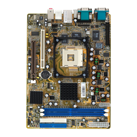
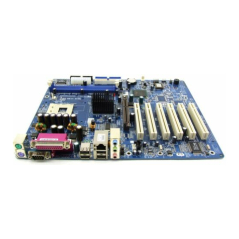
Shuttle HOT-597 User manual

- 45 -
HOT-597
Pentium™processor
Based AGP MAIN BOARD
User's Manual

- 1 -
NOTICE
Copyright 1999.
All Right Reserved
Manual Ver 1.0
All information, documentation, and specifications contained in this manual are subject to change without prior
notification by the manufacturer.
The author assumes no responsibility for any errors or omissions which may appear in this document nor does it make a
commitment to update the information contained herein.
TRADEMARKS
All the brands and product names referred to in this manual are trademarks or registered trademarks of their respective
holders.
FCC Notice:
This equipment has been tested and found to comply with the limits for a Class B digital device, pursuant to Part 15 of FCC
Rules. These limits are designed to provide reasonable protection against harmful interference in a residential installation.
This equipment generates, uses and can radiate radio frequency energy. If not installed and used properly, in strict accordance
with the manufacturer's instructions, may cause harmful interference to radio communications. However, there is no guarantee
that interference will not occur in a particular installation. If this equipment does cause interference to radio or television
reception, which can be determined by turning the equipment off and on, the user is encouraged to try to correct the interfer-
ence by one or more of the following measures :
Reorient or relocate the receiving antenna.
Increase the separation between the equipment and receiver.
Connect the equipment into an outlet on a circuit different from that to which the receiver is connected.
Consult the dealer or an experienced radio/television technician for help and for additional suggestions.
The user may find the following booklet prepared by the Federal Communications Commission helpful "How to Identify and
Resolve Radio-TV Interference Problems." This booklet is available from the U.S. Government Printing Office. Washington,
DC 20402, Stock 004-000-00345-4
FCC Warning
The user is cautioned that changes or modifications not expressly approved by the manufacturer could void the users authority
to operate this equipment.
Note : In order for an installation of this product to maintain compliance with the limits for a Class B device, shielded cables
and power cord must be used.
CE Notice:
Following standards were applied to this product, in order to achieve compliance with the electromagnetic compatibility :
- Immunity in accordance with EN 50082-1: 1992
- Emissions in accordance with EN 55022: 1987 Class B.

- 2 -
TABLE OF CONTENTS
T
T
PREFACE ....................................................................................................................3
CHAPTER 1 FEATURES..................................................................................................4
Accessories of HOT-597 ......................................................................................................................6
CHAPTER 2 HARDWARE INSTALLATION............................................................................. 7
Jumper Setting......................................................................................................................................7
CPU Configurations Table....................................................................................................................8
CPU Configurations - SW1, JA26 & J19.............................................................................................8
System Clock and CPU Multiplier Manual Setting - SW1 & JA26...................................................14
SDRAM Frequency Setting - JP9.......................................................................................................15
CPU Voltage Manual Setting - J19.....................................................................................................16
Flash EEPROM Vpp - JP5.................................................................................................................17
Clear CMOS - JP2..............................................................................................................................17
Connectors..........................................................................................................................................18
CHAPTER 3 MEMORY CONFIGURATION ........................................................................... 21
CHAPTER 4 FLASH UTILITY..........................................................................................22
CHAPTER 5 VIA VXD AGP DRIVER INSTALLATION ......................................................... 24
CHAPTER 6 BIOS SETUP ...........................................................................................25
Main Menu .........................................................................................................................................26
Standard CMOS Setup........................................................................................................................28
BIOS Features Setup...........................................................................................................................30
Chipset Features Setup........................................................................................................................32
Power Management Setup..................................................................................................................35
PNP / PCI Configuration Setup..........................................................................................................38
Integrated Peripherals.........................................................................................................................41
Password Setting.................................................................................................................................44

- 3 -
P
P
HOT-597 is a high performace, cost effective, and energy efficient mainboard for the imple-
mentation of AGP, PCI, and ISA in desktop personal computer systems from 66MHz to
100MHz based on 64-bit Socket-7 super-scalar processors.
HOT-597 mainboard is a highly integrated IBM PC/ATX compatible ATX form-factor
system board designed to meet the industry's most demanding desktop applications. Based
on the VIA's MVP3 chipset.
HOT-597 accept AMD K6-2, K6, K5, Intel Pentium P54C, Pentium MMX, IDT-C6 and
Cyrix/IBM 6x86, 6x86L, 6x86MX processors and also features high-performance pipelined
burst secondary cache memory support with size of 1024KB. The memory subsystem is
designed supports standard Fast Page Mode (FPM), EDO, SDRAM, and 100MHz SDRAM.
HOT-597 complies with the Accelerated Graphics Port Specification 1.0 and features
support for 66/68/75/83/95/100MHz CPU bus frequencies and the 66MHz AGP bus fre-
quency.
HOT-597 provides a new level of I/O integration. VIA MVP3 chipset provides increased
integration and improved performance over other chipset designs.
The VIA's MVP3 chipset provides an integrated Bus Mastering IDE controller with two high
performance Ultra 33 DMA IDE interfaces for up to four IDE devices.
The onboard I/O controller provides the standard PC I/O functions: floppy interface, two
FIFO serial ports, an IrDA device port and a SPP/EPP/ECP capable parallel port.
Up to four PCI local bus slots provide a high bandwidth data path for data-movement
intensive functions such as graphics, and up to three ISA slots complete the I/O function.
HOT-597 provides the foundation for cost effective, high performance, highly expandable
platforms, which deliver the latest in Pentium processor and I/O standard.
PREFACE

- 4 -
FEATURES
1
1
HOT-597 Mainboard is carefully designed for the demanding PC user who wants high perfor-
mance and many intelligent features in a compact package:
Chipset
Features VIA's 82C598MVP Chipset with I/O subsystems
Main Processor
AMD K6-2 266~450 MHz, AMD K6 166~300 MHz, K5 PR133~PR166,
Intel Pentium (P54C) 100~200 MHz, Pentium MMX (P55C) 166~233 MHz,
Cyrix/IBM 6x86 P166+~P200+, 6x86L P166+~P200+, 6x86MX PR200~PR333,
IDT-C6 200~225MHz
Secondary Cache
Onboard 512KB or 1024KB Pipelined Burst Cache.
Versatile Memory Supports
Equipped with three DIMM sockets for (8, 16, 32, 64 or 128MB) 168-pin 66MHz or
100MHz PC SDRAM memory modules up to 384 MB.
Expansion Slots
Provides four 32-bit PCI slots, three 16-bit ISA slots and one AGP slot.
AGP (Accelerated Graphics Port)
AGP Specification 1.0
HOT-597 main board equipped with an AGP slot for an AGP VGA card that supports
133MHz 2X mode for texture mapping z-buffering and alpha blending. AGP allows 3D
applications to run faster and smoothly.
Onboard I/O Chip
One Floppy port
One PS/2 mouse and Keyboard connector
Two high-speed UART compatible serial port
Serial Port 2 can also be directed from COM2 to the Infrared Module for wireless connec-
tions One parallel port with ECP and EPP capabilities
Onboard PCI Bus Master IDE Controller
Two Ultra DMA/33 Bus Master IDE Ports supports four IDE devices up to 33 MB/sec
IDE transfers and supports Enhanced PIO Modes 3 and 4 and Bus Master IDE DMA
Mode 2 devices
Onboard 20-pin ATX Power Supply
ATX power supply unit can connect to the 20-pin ATX power connector onboard, sup-
porting Suspend and soft-on/off by dual-function power button.

- 5 -
AdvancedPower Management
Features three power savings modes:Doze, Standby, and Suspend.
SupportsACPI (Advanced Configuration and Power Interface) function.
ACPI provides more efficient Energy Saving Features controlled by your operating
system theat supports OS Direct Power Management (OSPM) functionality.
System BIOS
Provides licensed Award BIOS V4.51PG on 2MB Flash EEPROM.
Supports Green PC, Desktop Management Interface (DMI), PnP, ACPI, NCR SCSI
BIOS and Virus Protection.
Board Size:
ATX form factor size 305mm x 190mm.

- 6 -
ACCESSORIES OF HOT-597
Figure 1

- 7 -
HARDWARE INSTALLATION
2
2
Figure 2-1
board.
The following examples show the conventions used in this chapter.
Finger 3 set to ON,
the others set to OFF
Finger 4, 6 set to ON,
the others set to OFF
Insert a jumper pack on J19
Row 2-3 to set CPU voltage
auto-detecting
Remove jumper pack from J19
and insert mini on pin A, C, D on
Row 1-2 to set voltage on 3.3V Table 2-1
This chapter is designed for explaining how to configure the HOT-597 hardware. After you install the
main board, you can set jumpers, install memory on the main board, and make case connectors. Refer to
this chapter whenever you upgrades or reconfigure your system.
JumperSetting
This section describe the necessary procedures and proper jumper settings to configure the HOT-597
main board.
Jumper pin headers show on right side are used to
configure system clock, CPU multiplier voltages and
SDRAM clock speed.
System Clock and CPU Clock Multiplier - SW1
DIP siwtch finger 1 to finger 3 are used to adjust
System Clock from 66 to 100 MHz, finger 4 to finger 6
used to adjust CPU Clock Multiplier from 1.5x to 5.5x.
CPU Voltages - J19
Jumper group J19 are used to adjust onboard voltages
output from Switching regulators to CPU.
Futher more, HOT-597 Mainboard provide intelligent
CPU Voltages detecting and auto-adjusting function.
Enable this function by inserting a mini jumper pack on J19 row 2/3 (factory default), none of other mini
jumpers are required on jumper group J19. HOT-597 Mainboard will assign proper voltages to CPU
automatically.
SDRAM Clock Speed - Jumper JP9
HOT-597 support 100MHz external clock speed AMD 266MHz and 400MHz K6-2, and which allows
the user to use 66MHz normal SDRAM DIMM or 100MHz PC/100 SDRAM DIMM. Jumpers JP9 are
used to set SDRAM DIMM clock speed synchronous with System Clock (CPU External Clock) or
synchronous with AGP Clock.
Those hardware settings are made through the use of jumper caps to connect jumper pins on the main

- 8 -
ProcessorSpeedSystem
Clock MultiplierProcessorSpeedSystem
Clock Multiplier
Intel
Pentium
P55CMMX
233 MHz66 MHz3.5x
AMDK6-2
450 MHz100 MHz4.5x
Cyrix/IBM
6x86MX
PR333 100 MHz2.5x
200 MHz66 MHz3x400 MHz100 MHz4xPR333 83 MHz3x
166 MHz66 MHz2.5x380 MHz95 MHz4xPR300 75 MHz3x
Intel
Pentium
P54C
200 MHz66 MHz3x366 MHz66 MHz5.5xPR300 66 MHz3.5x
166 MHz66 MHz2.5x350 MHz100 MHz3.5xPR266 83 MHz2.5X
133 MHz66 MHz2x333 MHz95 MHz3.5xPR266 66 MHz3.5X
100 MHz66 MHz1.5x333 MHz66 MHz5xPR233 75 MHz2.5x
IDT-C6225MHz75 MHz3x300 MHz100 MHz3xPR233 66 MHz3x
200MHz66 MHz3x300 MHz66 MHz4.5xPR200 75 MHz2x
AMDK6
300 MHz66 MHz4.5x266 MHz66 MHz4xPR200 66 MHz2.5x
266 MHz66 MHz4x
AMDK5
PR166 66 MHz2.5x
Cyrix/IBM
6x86 (L)
P200+75 MHz2x
233 MHz66 MHz3.5xPR133 66 MHz1.5xP166+66 MHz2x
200 MHz66 MHz3x
166 MHz66 MHz2.5x
CPU Configuration Table
CPU Configuration - SW1, JA26 & J19
SW1 and J19 are the Jumpers that you need to set your CPU on HOT-597. Make sure that you know
the type of CPU that you are installing and refer to the proper settings which are listed below.
Normally, CPU voltage is auto-detected on HOT-597 and is set to Auto-detected when HOT-597 is
delivered. If you have a higher frequency CPU or you want to set CPU frequency and voltage
manually, please refer to next two sections.
AMD-K5 Series CPUs Settings
ProcessorSpeedFrequency Setting
SW1,JA26
JumperBlock J19
Vcore/Vio
Auto-detect
AMD-K5
PR166
66MHzx2.5
3.52V/3.52V
PR133
66MHzx1.5
Table 2-3
Table 2-2

- 9 -
ProcessorSpeedFrequency Setting
SW1,JA26
JumperBlock J19
Vcore/Vio
Auto-detect
AMD K6
300 MHz
66MHzx4.5
2.2V/3.3V
266 MHz
66MHzx4
233 MHz
66MHzx3.5
233 MHz
66MHzx3.5 3.2V/3.3V
200 MHz
66MHzx3
2.9V/3.3V
166 MHz
66MHzx2.5
Table 2-4
AMD-K6 Series CPUs Settings
Note :The voltage of AMD-K6 233MHz may vary from market and CPU core.
Please ask your CPU provider for detail.

- 10 -
ProcessorSpeedFrequency Setting
SW1,JA26
JumperBlock J19
Vcore/Vio
Auto-detect
AMD K6-2
450 MHz
100MHzx4.5
2.2V/3.3V
400 MHz
100MHzx4
380 MHz
95MHzx4
366 MHz
66MHzx5.5
350 MHz
100MHzx3.5
333 MHz
95MHzx3.5
333 MHz
66MHzx5
300 MHz
100MHzx3
300 MHz
66MHzx4.5
266 MHz
66MHzx4
AMD K6-2 Series CPUs Settings
Table 2-5

- 11 -
ProcessorSpeedFrequency Setting
SW1,JA26
JumperBlock J19
Vcore/Vio
Auto-detect
Intel Pentium
(P54C)
200 MHz
66MHzx3
3.3V/3.3V
166 MHz
66MHzx2.5
133 MHz
66MHzx2
100 MHz
66MHzx1.5
Table 2-7
ProcessorSpeedFrequency Setting
SW1,JA26
JumperBlock J19
Vcore/Vio
Auto-detect
Intel Pentium
MMX(P55C)
233 MHz
66MHzx3.5
2.8V/3.3V
200 MHz
66MHzx3
166 MHz
66MHzx2.5
Table 2-6
Intel Pentium MMX (P55C) Series CPUs Settings
Intel Pentium (P54C) Series Settings

- 12 -
ProcessorSpeedFrequency Setting
SW1,JA26
JumperBlock J19
Vcore/Vio
Auto-detect
Cyrix/IBM
6x86MX
PR333
100MHzx2.5
2.9V/3.3V
PR333
83MHzx3
PR300
75MHzx3
PR300
66MHzx3.5
PR266
83MHzx2.5
PR266
66MHzx3.5
PR233
75MHzx2.5
PR233
66MHzx3
PR200
75MHzx2
PR200
66MHzx2.5
Table 2-8
Cyrix/IBM 6x86MX Series CPUs Settings

- 13 -
ProcessorSpeedFrequency Setting
SW1,JA26
JumperBlock J19
Vcore/Vio
Auto-detect
IDT-C6
225 MHz
75MHzx3
3.52V/3.52V
200 MHz
66MHzx3
ProcessorSpeedFrequency Setting
SW1,JA26
JumperBlock J19
Vcore/Vio
Auto-detect
Cyrix/IBM
6x86L
P200+
75MHzx2
2.8V/3.3V
P166+
66MHzx2
Cyrix/IBM
6x86
P200+
75MHzx2
3.52V/3.52V
P166+
66MHzx2
Table 2-9
Table 2-10
Cyrix/IBM 6x86/6x86L Series CPUs Settings
IDT-C6 Series CPUs Settings

- 14 -
System Clock and CPU Multiplier Manual Setting
- SW1 & JA26
For whom like to set up system manually, listed tables show all the System Clock and CPU Multi-
plier that HOT-597 can offer. Pin header 1~3 of SW1 and JA26 are used to adjust System Clock
from 60 MHz to 100 MHz. Pin header 4~6 of SW1 are used to adjust CPU core multiplier from
1.5X to 5.5X.
Table 2-11 shows the System Clock from 66 MHz to 100 MHz.
Table 2-12 shows CPU Multiplier from 1.5X to 5.5X.
MultiplierSW1(4-6) MultiplierSW1(4-6)
1.5 X / 3.5 X 4 X
2 X 4.5 X
2.5 X 5 X
3 X 5.5 X
CPU External CLK
CPU AGP PCI SW1(1-3)
/ JA26
66MHz66MHz33MHz
68MHz68MHz34MHz
75MHz75MHz37MHz
83MHz55MHz27MHz
95MHz63MHz31MHz
100MHz66MHz33MHz
Table 2-11
Table 2-12
Figure 2-2

- 15 -
SDRAM Frequency Setting - JP9
HOT-597 support 100MHz external frequency AMD K6-2, and which allows the user to use 66MHz
normal SDRAM DIMM or 100MHz PC/100 SDRAM DIMM. Jumpers JP9 are used to set SDRAM
frequency which synchronous with System Clock (CPU External Clock) or synchronous with AGP
External Clock.
This feature allows the user to use normal SDRAM with AMD K6-2 processor.
SDRAMFrequency Setting
JP9
Synchronouswith
SystemClock
(CPUExternalClock)
Synchronouswith
AGPClock
Table 2-13
Figure 2-3

- 16 -
CPU Voltage Manual Setting - J19
HOT-597 automatically detects and
adjusts the voltage to the proper voltage.
Jumper block J19 is used to set Auto-
matically or Manually adjust onboard
voltages output from Switching type
regulators to CPU by inserting or
removing mini jumper The voltage
settings are made through the use of
jumper caps to connect jumper pins on
the pin set A~E of Jumper block J19.
Voltage J19 Voltage J19
Auto
-setting 2.5 V
3.5 V 2.3 V
3.4 V 2.2 V
3.3 V 2.1 V
3.2 V 2.0 V
2.9 V 1.9 V
2.8 V 1.8 V
Table 2-14
Figure 2-4

- 17 -
CMOS Clear - JP2
HOT-597 mainboard supports jumper JP2 for
discharging mainboard’s CMOS memory.
This jumper can clear the CMOS data stored
in the subsystem chip. To clear the CMOS data
please follow listed steps:
1) Turn off the PC,
2) Remove the jumper cap from JP2 pin 1-2,
3) Insert the jumper cap to JP2 pin 2-3
for a brief while,
4) Remove the jumper cap from JP2 pin 2-3,
5) Reinsert the jumper cap to JP2 pin 1-2,
6) Turn on the PC.
Flash EEPROM Vpp - JP5
HOT-597 mainboard supports two types of
Flash EEPROM:
5 volt and 12 volt. By setting up jumper JP5,
the main board can use both 5V or 12V flash
EEPROM with new system BIOS files as they
come available.
JP5 Pin 2-3 Close for 12V Flash EEPROM
JP5 Pin 1-2 Close for 5V Flash EEPROM
Figure 2-5

- 18 -
Connectors
Front Panel Connectors (JP6)
Hardware Reset Connector - RST
Attach 2-pin hardware reset switch to it.
Closing the reset switch restarts the system.
PW-LEDConnector
Power LED connector is a 3-pin connector for
attached to the case's Power LED.
KeyLockConnector
KeyLock connector is a 2-pin connector for a
lock that may be installed on the system case
for enabling or disabling the keyboard.
Speaker Connector - Speaker
PC speaker connector may attach a 4-pin PC
speaker cable from the case to this connector.
SMI Connector - SMI
Hardware System Management Interface
connector may attach a 2-pin momentary switch
to it. When push it will force system get into
power saving mode, and the system will resume
when switch is pushed again.
GLED Connector - GLED
Attach a 2-pin Green LED cable to it. The Green LED lights when the system get into power
saving mode. The Green LED off when the system resume back to normal mode.
HD LED Connector - IDE
Attach a 2-pin IDE drive LED cable to this connector. The LED lights when an IDE device is
active.
ATX Power On/Off Switch Connector - PWR_BT
Attach a 2-pin momentary type switch to this connector for truning on or off your ATX power
supply.
Figure 2-6

- 19 -
Figure 2-7
Back Panel Connectors
COM1/COM2 Connectors
Attach COM1/COM2 device cables to these connectors.
PS/2 Keyboard & PS/2 Mouse Connector
Two 6-pin female PS/2 keyboard & Mouse Connectors is located at the rear of the main board.
PS/2 Mouse on top of connector and PS/2 Keyboard on the bottom of connector. Plug the PS/2
keyboard and mouse jack into this connector.
Parallel Port Connector
A 25-pin female connector is located at the rear of the main board. Plug the parallel port device
cable into this connector.
USB1/USB2 Port Connectors
Two female connectors are located at the rear of the board. Plug the USB devices jack into this
connector.
Other Connectors
ATX Power Supply Connector - J3
It is a 20-pin male header connector is connected to the ATX
power supply. The plug of the power supply will only insert in
one orientation because of the different hole shade and size.
Find the proper orientation and push down firmly making sure
that the pins are aligned.
IR Connector - JP3
Infrared device connector may attach a 5-pin infrared device
cable to this connector for enabling the infrared transfer func-
tion. This mainboard meets the specification of ASKIR and
HPSIR.
Table of contents
Other Shuttle Motherboard manuals

Shuttle
Shuttle FB86 User manual

Shuttle
Shuttle Spacewalker AK31 User manual

Shuttle
Shuttle AE25 User manual

Shuttle
Shuttle FB77 User manual

Shuttle
Shuttle Spacewalker AB30 User manual

Shuttle
Shuttle Spacewalker AK11 User manual

Shuttle
Shuttle MS52P User manual

Shuttle
Shuttle MV43VN User manual

Shuttle
Shuttle HOT-641/P User manual

Shuttle
Shuttle AB48 User manual

Shuttle
Shuttle FB65 User manual

Shuttle
Shuttle FV25 User manual

Shuttle
Shuttle HOT-595 User manual

Shuttle
Shuttle FN41V3 User manual

Shuttle
Shuttle AT30 User manual

Shuttle
Shuttle AK10 User manual

Shuttle
Shuttle FT20 User manual

Shuttle
Shuttle HOT-673 User manual

Shuttle
Shuttle MV43 User manual

Shuttle
Shuttle AV18 User manual