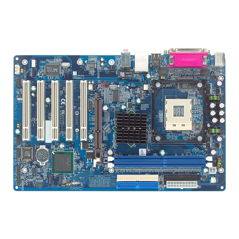
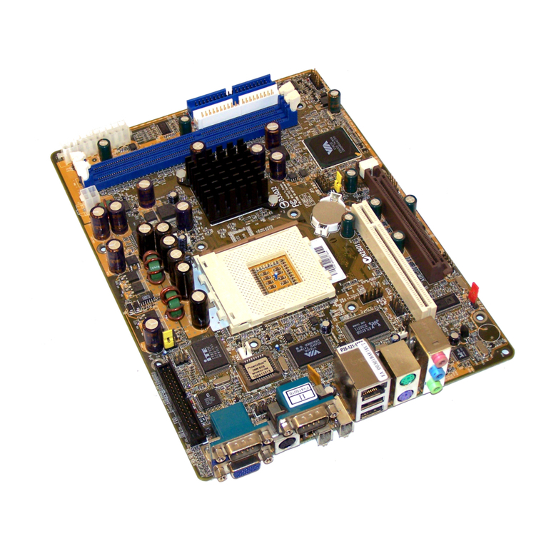
Shuttle HOT-591 User manual

HOT-591
Pentium™processor
Based AGPMAINBOARD
User's Manual

1
NOTICE
Copyright 1998.
AllRightReserved
Manual Ver 1.0
Allinformation, documentation, andspecifications contained inthis manual aresubject to changewithout prior
notificationbythemanufacturer.
The author assumes no responsibility for any errors or omissions which may appear in this document nor does it make a
commitment to update the information contained herein.
TRADEMARKS
All the brands and product names referred to in this manual are trademarks or registered trademarks of their respective
holders.
FCC Notice:
This equipment has been tested and found to comply with the limits for a Class B digital device, pursuant to Part 15 of FCC
Rules. These limits are designed to provide reasonable protection against harmful interference in a residential installation.
This equipment generates, uses and can radiate radio frequency energy. If not installed and used properly, in strict accordance
with the manufacturer's instructions, may cause harmful interference to radio communications. However, there is no guarantee
that interference will not occur in a particular installation. If this equipment does cause interference to radio or television
reception, which can be determined by turning the equipment off and on, the user is encouraged to try to correct the interfer-
ence by one or more of the following measures :
Reorient or relocate the receiving antenna.
Increase the separation between the equipment and receiver.
Connect the equipment into an outlet on a circuit different from that to which the receiver is connected.
Consult the dealer or an experienced radio/television technician for help and for additional suggestions.
The user may find the following booklet prepared by the Federal Communications Commission helpful "How to Identify and
Resolve Radio-TV Interference Problems." This booklet is available from the U.S. Government Printing Office. Washington,
DC 20402, Stock 004-000-00345-4
FCCWarning
The user is cautioned that changes or modifications not expressly approved by the manufacturer could void the users authority
to operate this equipment.
Note: In order for an installation of this product to maintain compliancewith the limits for a Class B device, shielded cables
and power cord must be used.
CE Notice:
Following standards were applied to this product, in order to achieve compliance with the electromagnetic compatibility :
- Immunity in accordance with EN 50082-1: 1992
- Emissions in accordance with EN 55022: 1987 Class B.


2
TABLE OF CONTENTS
T
T
PREFACE ........................................................................................................................3
CHAPTER 1 FEATURES ......................................................................................................4
Accessories of HOT-591 .......................................................................................................................... 6
CHAPTER 2HARDWARE CONFIGURATION.............................................................................7
Jumper Setting........................................................................................................................................... 7
CPUClock Configurations -DIP Switch SW2........................................................................................ 8
SystemClock and CPUMultiplier Setting Manually- SW2 ................................................................ 12
CPUVoltage Setting Manually - SW1................................................................................................... 13
CPUBurst Mode Jumper-JP3................................................................................................................ 14
Flash EEPROM Vpp - JP13................................................................................................................... 14
ClearCMOS -JP6................................................................................................................................... 14
Connectors............................................................................................................................................... 15
CHAPTER 3MEMORY CONFIGURATION ..............................................................................14
CHAPTER 4 FLASH UTILITY .............................................................................................18
CHAPTER 5 VIA VXD AGP DRIVER INSTALLATION ............................................................20
CHAPTER 6 BIOS SETUP ...............................................................................................23
MainMenu .............................................................................................................................................. 24
StandardCMOS Setup............................................................................................................................ 26
BIOS Features Setup............................................................................................................................... 28
Chipset Features Setup............................................................................................................................ 30
PowerManagement Setup ...................................................................................................................... 32
PCIConfiguration Setup......................................................................................................................... 35
Integrated Peripherals ............................................................................................................................. 38
PasswordSetting ..................................................................................................................................... 41

3
P
P
HOT-591mainboard isa highly integrated IBM PC/AT compatible AT form-factor system
boarddesigned to meet the industry's most demanding desktop applications. Based on the
VIA'sVP3 chipset.
HOT-591accept AMD K5, K6, Intel Pentium P54C, Pentium MMX, IDT-C6 and Cyrix/
IBM6x86, 6x86L, 6x86MX processors and also featureshigh-performance pipelinedburst
secondarycache memory supportwith size of512KB. Thememory subsystem isdesigned
tosupport upto 256MBof EDORAM, StandardFast PageDRAM andSDRAM instandard
72-pinSIMM socket and 168-pin 3.3 V DIMM socket.
HOT-591is equipped withan Accelerated GraphicsPort (AGP) slot,a high performance
interconnectfor graphic-intensiveapplication, suchas 3Dapplications. The AGPis inde-
pendentof the PCIbus andis designed toexclusively use with graphical-display devices.
HOT-591provides a new level of I/O integration. VIA VP3 chipset provides increased
integrationandimprovedperformance over other chipsetdesigns.
TheVIA's VP3 chipset provides an integrated Bus Mastering IDE controller withtwo high
performanceUltra 33DMA IDE interfaces for up to four IDE devices.
TheonboardI/Ocontrollerprovides the standard PCI/Ofunctions:floppyinterface, two
FIFOserial ports,an IrDAdevice portand aSPP/EPP/ECP capableparallel port.
Upto three PCI local bus slots provide a high bandwidth datapath for data-movement
intensivefunctions suchas graphics,and up to three ISA slots complete the I/O function.
HOT-591provides the foundation for cost effective, high performance, highly expandable
platforms,which deliver the latest in Pentium processor and I/O standard.
HOT-591Mainboard is carefully designed for the demandingPC user who wants high
performanceand many intelligentfeatures in acompact package:
PREFACE

4
FEATURES
1
1
Chipset
FeaturesVIA's82C597AT VP3 AGPChipsetwith I/O subsystems
MainProcessor
AMD K6 166~266 MHz, K5 PR75~PR166,
IntelPentium (P54C) 75~200 MHz, Pentium MMX (P55C) 166~233MHz,
Cyrix/IBM6x86 P120+~P200+,6x86L P200+,6x86MX PR166~PR233,
IDT-C6150~200MHz
SecondaryCache
Onboard512KBPipelinedBurstCache
VersatileMemorySupports
Equippedwith twoSIMM andtwo DIMM sockets for (8, 16, 32, 64 or 128MB) 72-pin EDO or
FPMand 168-pin SDRAM memory modules up to 256 MB
ExpansionSlots
One AGP slot
Three PCI slot
Three ISA slot
AGPSupport(AcceleratedGraphicsPort)
HOT-591main boardequipped withan AGPslot foran AGPVGA cardthat supports133MHz
2Xmode for texture mapping z-buffering and alphablending. AGP allows3D applications to run
faster and smoothly.
OnboardI/O Chip
One Floppy port
One PS/2 mouse and Keyboard connector
Two high-speed UART compatible serial port
SerialPort 2 can also be directed fromCOM2 tothe Infrared Module for wireless connections
Oneparallelportwith ECP and EPPcapabilities
OnboardPCI Bus MasterIDE Controller
TwoUltra DMA/33 Bus Master IDEPorts supportsfour IDE devices up to33 MB/sec
IDEtransfers and supports Enhanced PIO Modes 3 and 4and BusMaster IDE DMA
Mode2 devices
Onboard12-pin ATand 20-pinATX Power Supply
ATXpower supports soft-on/offfunction

5
SystemBIOS
LicensedBIOSwithadditionalfeature:
*FlashEEPROM(128KB) for BIOSupdate
*ISAPlug & Playextension
*Powermanagement
*SupportDMI (Desktop Management Interface) function
ACPI:
SupportACPI(AdvancedConfigurationandPowerInterface) function. ACPI provide
moreEnergy SavingFeatures for the future operating system supporting OS Direct
PowerManagement (OSPM) functionality.
BoardSize:
AT form factor size 220mm x 220mm.

6
ACCESSORIESOF HOT-591
Figure 1 : Accessories of HOT-591

7
HardwareConfiguration
2
2
Thischapter is designed for explaininghow to configure the HOT-591'shardware. After youinstall the
mainboard, youcan setjumpers, installmemory onthe mainboard, andmake caseconnectors. Refer to
thischapter whenever youupgrades or reconfigureyour system.
Jumper Setting
Thissection describe the necessary proce-
duresand proper jumpersettings to configure
theHOT-591 mainboard.
Jumperpin headers and DIP Switch show on
rightside are used to configuresystem clock,
CPUmultiplier and CPU voltages.
SystemClock -
PinHeader 1~6 of Jumper JP1
Pinheader 1~6 are used toadjust System
Clock from 50MHz to 83 MHz.
CPU Multiplier -
PinHeader 7~12 of Jumper JP1
Pinheader 7~12are used to adjust CPU core
multiplierfrom 1.5X to5.5X.
CPUVoltages Auto/Manual Figure 2-1 : SW1 & SW2 location
Insert a jumper pack on SW 1
Row B-C to set CPU voltage
auto-detecting
Remove jumper pack from SW1
and insert mini on pin 1, 3, 4 or
Row A-B to set voltage on 3.3V
Jumper-J19
HOT-591automaticallydetectsandadjuststhevoltage to the proper voltage.
Jumperblock J19 isused to setAutomaticallyor Manually adjustonboard voltages output
fromSwitching type regulators to CPU by inserting or removing mini jumperfrom pin
headers.(please also referto page 13)
Thosehardware settings are made through the useof jumpercaps to connect jumper pins on
the main board.
Thefollowing examplesshow theconventions usedin thischapter.
Insertminijumperson pin1-2,3-4
of JP1
Insertminijumperson pin1-2,7-8
and 9-10 ofJP1

8
CPU Clock Configuration - Jumper JP1
JumperJP1 andJumper BlockJ19 arethe Jumpersthat youneed toset foryour CPU on HOT-591.
Makesure thatyou know the type of CPU that you are installing and refer to the proper settings which
arelisted below. Normally, CPUvoltage is auto-detectedon HOT-591 andis set to Auto-detected when
HOT-591 is delivered. If you have a higher frequency CPU or you want to set CPU frequency and
voltagemanually, please refer to nexttwo sections.
Intel Pentium (P54C) Series CPUs Settings
ProcessorSpeedFrequency Settings
JumperJP1
JumperBlock J19
Vcore/Vio
Auto-detect
IntelPentium
(P54C)
200 MHz
3.3V/3.3V
166 MHz
150 MHz
133 MHz
120 MHz
100 MHz
90 MHz
75 MHz
Table 2-1

9
Intel Pentium MMX (P55C) Series CPUs Settings
ProcessorSpeedFrequency Settings
JumperJP1
JumperBlock J19
Vcore/Vio
Auto-detect
IntelPentium
MMX(P55C)
233 MHz
2.8V/3.3V
200 MHz
166 MHz
Table 2-2
AMD-K6 Series CPUs Settings
ProcessorSpeedFrequency Settings
JumperJP1
JumperBlock J19
Vcore/Vio
Auto-detect
AMD-K6
266 MHz
2.2V/3.3V
233 MHz
233 MHz3.2V/3.3V
200 MHz
2.9V/3.3V
166 MHz
Table 2-3
Note :The voltage of AMD-K6 233MHz may vary from market and CPU core. Please ask your
CPU provider for detail.

10
AMD-K6 Series CPUs Settings
ProcessorSpeedFrequency Settings
JumperJP1
JumperBlock J19
Vcore/Vio
Auto-detect
AMD-K5
PR166
3.52V/3.52V
PR133
PR120
PR100
PR90
PR75
Table 2-4
ProcessorSpeedFrequency Settings
JumperJP1
JumperBlock J19
Vcore/Vio
Auto-detect
IDT-C6
200 MHz
3.52V/3.52V
180 MHz
150 MHz
IDT-C6 Series CPUs Settings Table 2-5

11
Cyrix/IBM 6x86/6x86L/6x86MX Series CPUs Settings
ProcessorSpeedFrequency Settings
JumperJP1
JumperBlock J19
Vcore/Vio
Auto-detect
Cyrix/IBM
6x86L
P166+
2.8V/3.3V
P150+
Cyrix/IBM
6x86
P166+
3.52V/3.52V
P150+
P120+
Table 2-6
Cyrix/IBM
6x86MX
PR266
2.9V/3.3V
PR233
PR200
PR166

12
System Clock and CPU Multiplier Setting Manually - JP1
Forwhom like to set up system manually, listed tables show all theSystem Clock and CPU
Multiplierthat HOT-591 can offer. Pin header 1~6 areused to adjust System Clock from
50MHz to 83 MHz. Pin header 7~12 are used to adjust CPU core multiplier from 1.5X to
5.5X.
Table2-7 showsthe System Clock from 50 MHz to 83 MHz.
Table2-8 showsCPU Multiplier from 1.5X to 5.5X.
Note: On HOT-591 75 and 83 MHz is for over-clock usage, it is not a recommended
generalpractice.
Multiplier1.5X2 X 2.5X3 X 3.5X
JP1
P7~P12
Multiplier4 X 4.5X5 X 5.5X
JP1
P7~P12
Table 2-8
System
Clock 50MHz60MHz66MHz75MHz83MHz
PCI
Clock 25MHz30MHz33MHz37.5MHz41.5MHz
JP1
P1~P6
Table 2-7
Figure 2-2 : JP1 Jumper location

13
CPU Voltage Setting Manually - J19
HOT-591automaticallydetects and adjusts thevoltage
tothe proper voltage.
Jumperblock J19is usedto setAutomatically orManu-
allyadjust onboard voltages outputfrom Switching type
regulatorsto CPUby inserting or removing mini jumper
from pin headers.
Thevoltage settings are made throughthe use of jumper
caps to connect jumper pins on the pin set 1~4 of
Jumper block J19.
Figure 2-3 : SW1 Jumper Block location
Voltage J19 Voltage J19
Auto
-setting
2.8 V
2.7 V
3.52 V 2.6 V
3.4 V 2.5 V
3.3 V 2.4 V
3.2 V 2.3 V
3.1 V 2.2 V
3.0 V 2.1 V
2.9 V 2.0 V Table 2-9

14
Power Supply Type Jumper - JP3
Dueto differentdesigns, there are two Power Supply Type : 12-pin AT Power Supplyand
20-pinATX Power Supply. HOT-591 support both type ofPower Supply. Select the correct
typeaccording tothe Power Supply you are using.
JP8AT/ATXPowerSelection
12-PinATPowerSupply
20-PinATXPowerSupply
CMOS Clear - JP2
HOT-591 mainboard supports jumper JP6 for
dischargingmainboard’sCMOS memory.
Thisjumper can clear the CMOSdata stored
in the subsystem chip. To clear the CMOS data
pleasefollow listedsteps:
1) Turn off the PC,
2)Remove thejumper cap from JP2 pin 1-2,
3)Insert the jumper cap to JP2 pin 2-3
for a brief while,
4)Remove thejumper cap from JP2 pin 2-3,
5)Reinsert the jumper cap to JP2 pin 1-2,
6) Turn on the PC.
Figure2-4: JP8AT/ATX PowerJumper location
Figure2-4:FlashTypeJumper
JP5location
Flash EEPROM Vpp - JP5
HOT-591mainboardsupports two typesof
Flash EEPROM:
5volt and12 volt.By settingup jumperJP13,
the main board can use both 5V or 12V flash
EEPROMwith new system BIOSfiles as they
come available.
JP5Pin 2-3 Close for 12V Flash EEPROM
JP5 Pin 1-2 Close for 5V Flash EEPROM
Figure2-4:Clear CMOS
JumperJP2location

15
Connectors
Front Panel Connectors (JP6)
Hardware Reset Connector - RST
Attach 2-pin hardware reset switch to it. Closing the
resetswitch restarts the system.
KeyLockConnector
- PW-LED Key-Lock
KeyLock& Power LEDconnector is a5-pin connector
fora lock that may be installed on the system case for
enablingor disabling the keyboard. It alsoattached to
the case's Power LED. Pin 1 and 3 are for power LED
and pin 4 and 5 are for keylock, pin 2 is useless.
Speaker Connector - Speaker
PCspeaker connector mayattach a 4-pinPC speaker
cablefrom thecase tothis connector.
SMI Connector - SMI
HardwareSystem Management Interface connector may attach a2-pin momentary switch to it.
Whenpush it will force system get into power saving mode, and thesystem will resume when
switchispushed again.
GLED Connector - GLED
Attacha 2-pin Green LED cable to it. The Green LEDlights when the system get into power
saving mode. The Green LED off when the system resume back to normal mode.
HD LED Connector - IDE
Attacha 2-pinIDE driveLED cableto thisconnector. The LEDlights whenan IDEdevice is
active.
ATX Power On/Off Switch Connector - PWR_BT
Attacha 2-pin momentary type switchto this connector for turningon oroff your ATX power
supply.
Figure2-5:FrontPanelCon-
nectorlocation

16
Back Panel Connectors
COM1/COM2 Connectors - J9/J10
AttachCOM1/COM2connectorcablestotheseconnectors.
PS/2 Mouse Connector - J6
Themain boardprovides a5 pins PS/2 mouse connector for an optional PS/2 mouse
cable. Diagramon the right side indicates the pinoutof pin header.
HOT-591 mainboardsuppliestwo types ofoptionalPS/2 mouse adapter
cable,type 1have 6-holesplug with hole 2 and hole 6 wireless; type 2
have5 holes plug with hole2 wireless.
Caution: Whena PS/2mouse isused, makesure connectPS/2 mouse
adaptercable hole 1to thepin 1 ofonboard PS/2 connector (J6). Reversed
connectingmay cause damage to your PS/2 mouse.
Parallel Port Connector - J8
A26-pin malepin header is located at the rear of the main board. Plug the parallel port connec-
torcable into thisconnector.
USB1/USB2 Port Connectors - J14
The USB pin headers located at the rear of the board. Plug the USB
connectorcable into thisconnector.
OtherConnectors
ATX Power Supply Connector - J3
Itis a twenty-pin male header connector. Plug the connector from the power directlyonto the
boardconnector whilemaking surethe pin1 isin itsposition. The mainboard requiresa power
supplywith at least 200watts and "powergood signal.
Figure2-6:ATXPowerSupplyConnector Figure 2-7:AT Power Supply Connector

17
AT Power Supply Connectors - J2
Itis a twelve-pin male header connector. Plug the connector from the power directlyonto the
boardconnector whilemaking surethe pin1 isin itsposition. The mainboard requiresa power
supplywith at least 200watts and "powergood signal.
IR Connector - JP3
Infrareddeviceconnector may attach a5-pin infrared device cabletothis connector forenabling
theinfraredtransfer function. This mainboardmeetsthe specification ofASKIRand HPSIR.
CPU, Chassis(or AGP) cooling Fan connectors - Fan1 & 2
Themain boardprovidesthreeonboard 12Vcooling fan powerconnectors forCPU (Fan 2),
AGPdevice (Fan1) coolingfan. Depending on the fan maker, the wiring and plug may be
different.The red wire should be connected to+12V andblack wire should be connected to
ground (GND)
Wake-On-LAN Connectors - J12
Attacha 3-pin connector from the LAN card which supports the Wake-On-LAN(WOL) func-
tion. This function lets users wake up the connected system through the LAN card.
( Note:Recently, only Intel LAN card supportWake-On-LAN function)
Figure 2-8: FAN 1, FAN 2 & WOL (J12)

18
MemoryConfiguration
3
3
TheHOT-591 mainboard providestwo72-pin SIMM socketsand two 168-pinDIMM
socketsthat make it possible to install up to 256MB of RAM. The SIMMsocket support
4MB,8MB, 16MB, 32MB, 64MB and 128MB 5V single- ordouble-side fastpage or EDO
DRAMmodules, andDIMM socketsupport 8MB,16MB, 32MB,64MB, and128MB 3.3V
single-or double-side SDRAM, fast page, or EDO modules.
Thetwo SIMM sockets are arranged in a single bank, the two DIMMsockets are arranged in
twobanks of one socket each. Each bank provides a 64/72-bitwide datapath.
Note: Maximummemorysizeis256MBtotalforallSIMMorDIMM sockets.
If using SIMM modules, each bank must be filled with a pair of same
modules.
Theuser should not populate both 5V SIMM modules &3.3VDIMM
modulesat the same time.
Thememory configuration tables on next page list the SIMMs and DIMMs memory configu-
ration.
Figure2-9:SIMMs &DIMMssocket location

19
SIMM 1SIMM 2DIMM 1DIMM 2TOTAL
4 MB 4 MB —— —— 8 MB
8 MB 8 MB —— —— 16 MB
16 MB 16 MB —— —— 32 MB
32 MB 32 MB —— —— 64 MB
64 MB 64 MB —— —— 128 MB
128 MB 128 MB —— —— 256 MB
—— —— 8 MB —— 8 MB
—— —— 8 MB 8 MB 16 MB
—— —— 16 MB —— 16 MB
—— —— 16 MB 16 MB 32 MB
—— —— 32 MB —— 32 MB
—— —— 32 MB 32 MB 64 MB
—— —— 64 MB —— 64 MB
—— —— 64 MB 64 MB 128 MB
—— —— 128 MB —— 128 MB
—— —— 128 MB 128 MB 256 MB
—— —— 8 MB 16 MB 24 MB
—— —— 8 MB 32 MB 40 MB
—— —— 8 MB 64 MB 72 MB
—— —— 8 MB 128 MB 136 MB
—— —— 16 MB 32 MB 48 MB
—— —— 16 MB 64 MB 80 MB
—— —— 32 MB 64 MB 96 MB
—— —— 32 MB 128 MB 160 MB
—— —— 64 MB 128 MB 192 MB
Table of contents
Other Shuttle Motherboard manuals

Shuttle
Shuttle FB81 User manual

Shuttle
Shuttle HOT-603 User manual

Shuttle
Shuttle HOT-649A User manual

Shuttle
Shuttle Spacewalker MV25 User manual

Shuttle
Shuttle AK12 User manual

Shuttle
Shuttle Spacewalker AK11 User manual

Shuttle
Shuttle FV24 User manual

Shuttle
Shuttle Spacewalker MV17 User manual

Shuttle
Shuttle HOT-595 User manual

Shuttle
Shuttle AV18 User manual

Shuttle
Shuttle FX43G User manual

Shuttle
Shuttle av61 User manual

Shuttle
Shuttle Spacewalker MS51 User manual

Shuttle
Shuttle FT62 User manual

Shuttle
Shuttle HOT-679V User manual

Shuttle
Shuttle HOT-623 User manual

Shuttle
Shuttle MB47N User manual

Shuttle
Shuttle HOT-679 User manual

Shuttle
Shuttle AK10 User manual

Shuttle
Shuttle AT30 User manual