Shuttle HOT-687V User manual

HOT-687V
PPGACeleron/Coppermine processor
Based AGPMAINBOARD
User's Manual

Shuttle®SpacewalkerTM HOT-687V
PPGACeleron/CopprtminrprocessorbasedAGPsetMainboard
Manual Version 2.0
Copyright
Copyright©2000 by Shuttle®Inc. AllRightsReserved.
Nopart of this publication may be reproduced, transcribed, stored ina retrieval system,
translated into any language, or transmitted in any form or by any means, electronic, me-
chanical,magnetic,optical,chemical,photocopying,manual,orotherwise, without prior
written permission from Shuttle®Inc.
Disclaimer
Shuttle®Inc.shall not be liable for any incidental or consequential damagesresulting from
theperformance or use of this product.
Thiscompanymakes no representations or warranties regarding the contentsofthis
manual. Information in this manual has been carefully checked for reliability; however, no
guarantee is given as to the correctness of the contents. In the interest of continued product
improvement,this company reserves the right to revise the manual or include changes in the
specifications of the product described within it at any time without notice and without obliga-
tion to notify any persion of such revision or changes. The information contained in this
manualisprovidedforgeneraluseby the customers.
Trademarks
Spacewalkerisa registerred trademark of Shuttle Inc.
Intel,Pentium is a registered trademarks of Intel Corporation.
PS/2isaregistered trademark of IBM Corporation.
AWARDisaregisteredtrademarkofAward Software Inc.
Microsoftand Windows are registered trademarks ofMicrosoftCorporation.
General Notice: Other brandandproductnames used herein areforidentificationpurposes
onlyand may be trademarks of theirrespectiveowners.
M314

- 2 -
FederalCommunicationsr Commission (FCC)
ComplianceNotice
This equipment has been tested and found to comply with the limits for a Class B digital
device, pursuant to Part 15 of FCC Rules. These limits are designed to provide reasonable
protectionagainstharmful interference in a residential installation.
Thisequipmentgenerates,uses and can radiate radio frequency energy. If not installed and
usedproperly, in strict accordance withthemanufacturer's instructions, may cause harmful
interferenceto radio communications. However, there is noguaranteethatinterferencewill
not occur in a particular installation. If this equipment does cause interference to radio or
television reception, which can be determined by turning the equipment off and on, the user
is encouraged to try to correct the interference by one or more of the following measures :
Reorientorrelocatethe receiving antenna.
Increasetheseparation between the equipment and receiver.
Connect the equipment into an outlet on a circuit different from that to which the receiver is
connected.
Consultthe dealer or an experienced radio/televisiontechnicianforhelpand for additional
suggestions.
Theuser may find the following bookletpreparedbytheFederal Communications Commis-
sion helpful "How to Identify and Resolve Radio-TV Interference Problems." This booklet is
availablefromthe U.S. Government Printing Office. Washington, DC 20402,Stock004-000-
00345-4
CENotice
Thisdevicecomplieswiththe requirements oof the EEC directive 89/336/EEC with regard to
EMC(ElectromagneticCompatibility). Following standards are applied to this product, in
ordertoachievecompliancewiththeEMC:
Immunityisin accordance with EN 50082-1 (1992).
Emissionsare in accordance with EN55022(1987) Class B.

- 3 -
TABLE OFCONTENTS
T
T
CHAPTER 1 INTRODUCTION ...........................................................................................4
CHAPTER 2 FEATURES .................................................................................................5
Specification .................................................................................................................................5
Accessoriesof HOT-687V..........................................................................................................7
CHAPTER 3 HARDWARE INSTALLATION ...........................................................................8
InstallTheCPU ...........................................................................................................................8
ThePPGA Celeron Processor..................................................................................................8
Jumpers.........................................................................................................................................9
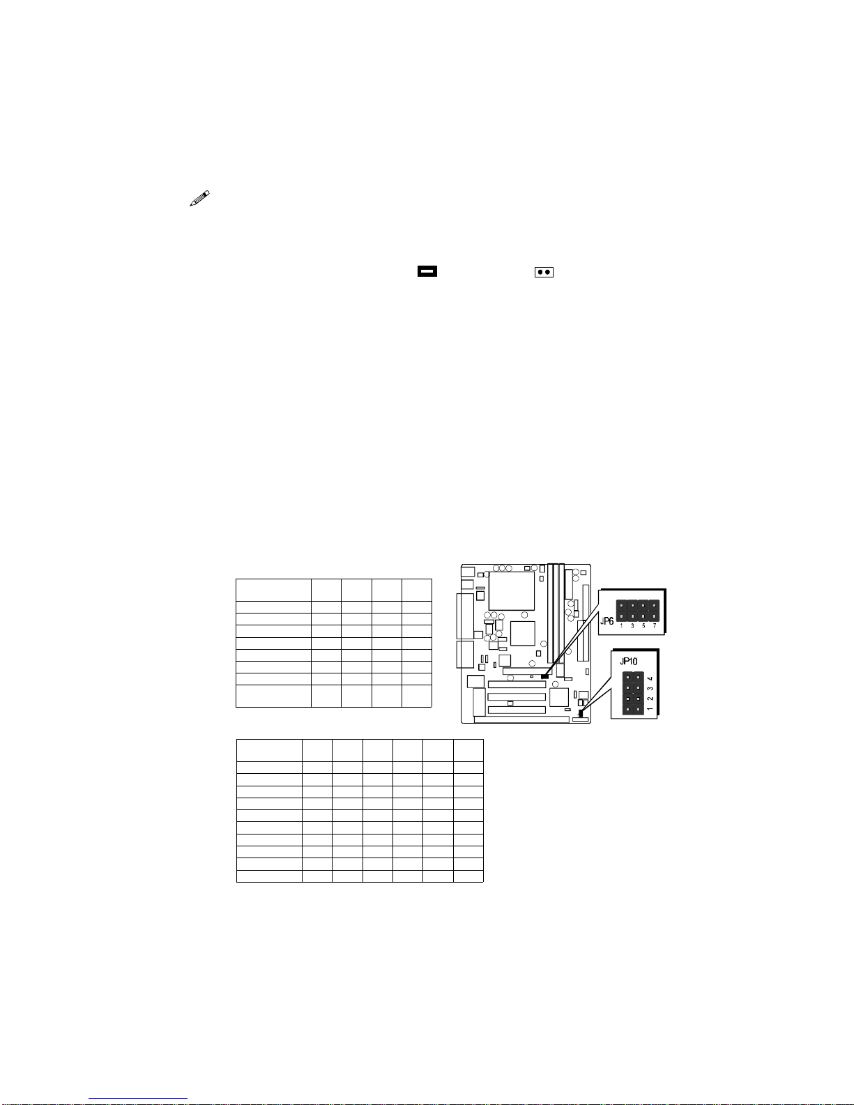
CPU Clock Speed and ratio Selection - JP6 and JP10...........................................................9
Force CPU FSB at 100/133MHz - JP5..................................................................................10
On Board Audio ControllerSetting - SJP1 ...........................................................................11
ClearCMOS - JP9..................................................................................................................11
Keyboard& PS/2 Mouse Power-on Setting - JP3 ................................................................11
Connectors..................................................................................................................................12
FrontPanelConnectors(JP11) ..............................................................................................12
(SPEAKER / IDE LED / PW ON / RST / PW LED / EPMI / GREEN LED)
BackPanelConnectors ..........................................................................................................13
(COM1 / COM2 / PS/2 Keyboard & PS/2 Mouse / Parallel Port / USB1 / USB2 /
Line-Out/ Line-In / Mic/In / GAME/MIDI)
Other Connectors....................................................................................................................14
(ATX Power Supply / IR / Audio /FAN / EISCA / Wake-On-LAN / IDE &
Floppy / SB-LINK)
CHAPTER 4MEMORY CONFIGURATION .........................................................................17
CHAPTER 5 FLASH UTILITY ........................................................................................18
CHAPTER 6SOFTWARE ..............................................................................................20
CHAPTER 7 BIOS SETUP ..........................................................................................24
TheMain Menu .........................................................................................................................25
StandardCMOSSetup .............................................................................................................27
BIOSFeatures Setup.................................................................................................................29
ChipsetFeaturesSetup .............................................................................................................32
PowerManagement Setup........................................................................................................35
PnP/PCIConfigurationSetup..................................................................................................38
LoadBIOS/SETUPDefaults ....................................................................................................40
IntegratedPeripherals ..............................................................................................................41
PasswordSetting........................................................................................................................45
Save& Exit/Exit Without Saving ............................................................................................46

- 4 -
1
1INTRODUCTION
Congratulations on your purchase of the HOT-687Vcomputer mainboard.
HOT-687Vis a highlyintegratedIBMPC/ATX compatiblesystemboarddesigned to meettheindustry's
mostdemandingdesktopapplications.
Basedon the VIA VT82C693AAGPset chipset which supportup to 600+MHz PPGACeleron
processorwithMMXtechnology and Coppermine FC-PGA 667+MHz.
HOT-687Visequipped with an Accelerated Graphics Port (A.G.P.),ahigh-performance interconnect
forgraphic-intensive application, such as 3Dapplications. The A.G.P. is independentof the PCI bus
andis designed to exclusively usewith graphical-display devices. The HOT-687V supports3.3 V
A.G.P.devices with data transfer rates upto 133 MHz, allowing data throughputof 500 MB/sec.
TheVIAVT82C693AAGPsetchipsetprovidesanintegratedBusMasteringIDEcontrollerwithtwo
highperformance IDE interfaces which allowsup to four IDE devices connection and up to 66 MB/
sec of data transfer rates.
OnboardFM801 is an advanced PCIaudio controller, it is compatible withMicrosoft Windows,
DirectXandAdlib Music Synthesizer, Sound Blaster Pro andsupportsthousands of DOS games.
Theon-boardI/O controller providesstandardPCI/O functions:
floppydrive interface, two FIFO serial ports, anIrDA device port and a SPP/EPP/ECP capable
parallel port.
HOT-687V is built with three PCI local bus slots providing a high bandwidth data path for data-
movementintensivefunctions such as graphics, and with one ISA slot.
HOT-687Vprovidesthefoundation for cost effective, high performance andhighlyexpandable
platforms,which delivers the latest inthe Intel FC-PGA Coppermine processor andnew advanced
chipset technology.

- 5 -
2
2FEATURES
Specification
TheHOT-687V Mainboard is carefully designedfor the demanding PC user whowants high
performanceandmany intelligent features in a compact package:
Chipset:
FeaturesVIAVT82C693A AGPset withI/Osubsystems.
CPUSupport:
IntelPPGACeleron processor 300~600+ MHz.
Intel Coppermine FC-PGA 500~667+ MHz.
VersatileMemorySupports:
Supports threebanksofnormal or PC66/PC100/PC133 SDRAM maximum memory size
upto768MB.
ConfigurablesupportforECC(ErrorCheckingandCorrecting)
PCIand ISAExpansion Slots:
Providesthree32-bitPCIslots,one16-bitISAslotandoneAGPslot.
AGP(Accelerated GraphicsPort):
AGP Specification 1.0
HOT-687Vmain board equipped with an AGP slot for an AGP VGA card that supports
133MHz2X mode for texture mappingz-buffering and alpha blending. AGP allows 3D
applications to run faster and smoothly.
OnboardI/O:
OneFloppyport;
OnePS/2 mouse and PS/2 Keyboard port connector
Twohigh-speedUART compatible serial ports
SerialPort 2 can also be directed from COM2 tothe Infrared Module for wireless connections.
Oneparallel port with ECP and EPP capabilities.
OnboardAudio Controller:
Proprietarylogicfor Real DOS games support
HardwareSynthesizerforAdLibandGeneralMIDIcompatibility
OptionalQSound HSP dynamic 3-D positional audio suport
S/PDIFdigitaloutputport
Built-in SRC (sampling rate converter)

- 6 -
OnboardPCI Bus Master IDE Controller:
Two UltraDMA33/66BusMasterIDEPorts supports four IDE devices up to 66 MB/sec
IDEtransfers and supports Enhanced PIOModes 3 and 4 and Bus Master IDE DMA Mode 2
devices.
Onboard20-pinATX Power Supply:
ATX power supply unit can connect to the 20-pin ATX power connector onboard, supporting
Suspendandsoft-on/offbydual-functionpowerbutton.
SystemBIOS:
ProvideslicensedAwardV4.51PG BIOS on Flash EEPROM.
SupportsGreenPC,DMIandBundledwith NCR SCSI BIOS.
ACPI:
Support ACPI(Advanced Configuration andPower Interface) function. ACPI provide
moreEnergySaving Features for the future operating system supporting OS DirectPower
Management(OSPM)functionality.
BoardSize:
Micro-ATXform factor 244mm x 190mm.
AdvancedFeatures:
LowEMI --SpreadSpectrumbuilt in - ±0.5% or ±0.3% modulation and automaticclock
shut-offof unused PCI/SDRAMS slots toreduce the EMI.
DualFunction Power Button -- The system can be one of two states, one is Suspend mode
andthe other is the Soft-off mode. Pushing the power button for less than 4 seconds will
place the system into Suspend mode. When push the power button for more than 4 seconds,
thesystem enters the Soft-off mode.
Wake-On-LAN --Thesystem will power-on automatically byactivatingofLAN.
(Thisfunction support Intel LAN card only).
ModemRing Power-on -- The system willpower-onautomatically by activating of modem
ring.
PS/2Keyboard& Mouse Power-on -- Thesystem will power-on automatically by stroke
keyboard or double click PS/2 mouse.
OptionalFeatures:
VoltagesMonitoring --Systemvoltageslevelsare monitored to ensure stable current to
mainboard components.
Systemvoltages include VCORE and VTT for CPU, and +5V, +12V, -5V, -12V for system.
FANStatusMonitoring -- To prevent CPU overheat,CPUfansis monitored for RPM and
failure.(CPU Cooling FAN with RPMsensor is required)

- 7 -
Accessories of HOT-687V

- 8 -
Figure 3-2
3
3HARDWARE INSTALLATION
Thenyou should have a CPU fan that
will cover the face of the CPU. Apply
thermaljelly to the CPU metallic top and
theninstallthefan onto the CPU. (Figure
3-2 )
Install The CPU
The Installation PPGA Celeron Processor
HOT-687Vmainboard provides a 370-pin ZIF Socket370 for Intel PPGACeleron and FC-
PGA Coppermine CPU. The CPU that came with the mainboard should have a fan attached
to it to prevent overheating. If this is not the case then purchase a fan before you turn on
yoursystem.
Toinstall a CPU, first turn off your system and remove its cover. Locate the ZIF Socket370
andopen it by first pulling the lever sideways away from the socket then upwards to a 90-
degreeright angle. Insert the CPU with the correct orientation asshown.(Figure 3-1) Use
the notched corner of the CPU as your guide. The notched corner should point towards the
end of the lever. Notice that there are two blank area where one hole is missing from that
corner of the square array of pin holes. Because the CPU has a corner pin for two of the four
corner,the CPU will only fit in the one orientationn, hold down on the CPU and close the
socket’slever.
Figure 3-1

- 9 -
Jumpers
Severalhardwaresettings are made through the use of jumper caps toconnectjumperpins
on the main board. The jumper's pin 1 on main board will be on the top or on the left when
holdingthemain board with the keyboard connector away from yourself.
Jumpers with two pins will be shown as for Close (On) and for Open (Off).
To connect the pins, simply place a plastic jumper cap over the two pins.
CPU Host Frequency Setting - JP6 and JP10
TheCPU host frequency is set to Auto-detectingbyBIOS. It is defined according to Intel
CeleronCPUspecification. We strongly advise novice users not tomodifythe original
setting,forsettinganincorrectvaluemay damage your CPU.
Forexperiencedusers,theHOT-687Vmainboardprovides an alternative Hard-Configure
functionto adjust your CPU host frequency manually.
Note: Beforeyouadjust your CPU host frequency by jumper,youneed to
setCPU Host Clock (CPU/PCI) toDisabled in Chipset Features Setupof
BIOSsetup program.
Insert mini-jumper caps properly on JP6 and JP10 to reach desired CPU
HostFrequency, as shown in the following table.
SystemClock
(JP6) 1-2 3-4 5-6 7-8
66MHzOFF OFF ONON
75MHzOFF ONONON
83MHzONOFF ONON
100MHzOFF OFF OFF ON
103MHzONONOFF ON
112MHzOFF ONOFF ON
124MHzONOFF OFF OFF
133 MHz/
(BIOSSetup)OFF OFF OFF OFF
Figure 3-3
Multiplier
(JP10) 1-6 2-7 3-8 4-9(66)
MHz(100)
MHz
3.5XONOFF ONOFF 350
4XOFF ONONON400
4.5XOFF ONONOFF 300 450
5XOFF OFF ONON333 500
5.5XOFF OFF ONOFF 366 550
6XONONOFF ON400 600
6.5XONONOFF OFF 433 650
7XONOFF OFF ON466 700
7.5XONOFF OFF OFF 500
8XOFF ONOFF ON
Table 3-1
Table 3-2
Note:Normally,Celeron andCoppermine processor's ratio are not adjustable.

- 10 -
CPU Host Clock and Clock Ratios Configuration Table (Table 3-3) shows the PPGA Celeron
processor300 MHz ~ 600+ MHz andCoppermine FC-PGA 500~667+ MHz quicksetting on
themainboard.
Processor300 MHz
(66MHzx4.5)333 MHz
(66MHzx5)366 MHz
(66MHzx5.5)400 MHz
(66MHzx6)433 MHz
(66MHzx6.5)466 MHz
(66MHzx7)500 MHz
(66MHzx7.5)350 MHz
(100MHzx3.5)
SystemClock
JP6
Multiplier
JP10
Processor400 MHz
(100MHzx4)450 MHz
(100MHzx4.5)500 MHz
(100MHzx5)550 MHz
(100MHzx5.5)600 MHz
(100MHzx6)533 MHz
(133MHzx4)600 MHz
(133MHzx4.5)667 MHz
(133MHzx5)
SystemClock
JP6
Multiplier
JP10
Table 3-3
SetCPUhost clock Auto-detecting
andsettingbysystemBIOS(De-
fault)
SetCPUhost clock hard-configure
to 100MHz.
SetCPUhost clock hard-configure
to 133MHz.
However,HOT-687V provide over clocking featureto processor host clock, it isnot a
recommendedpractice, for this may cause severedamage to the system.
Warning: Over-clocking is not a recommended practice for it may damage both the
mainboardand the processor.
Figure 3-4
HOT-687Vmainboard provide jumper JP5 to setCPUhost clock auto-detect by system
BIOSor hardware configure the CPUhost clock to 66MHz, 100MHz or133MHz manually
forover-clocking your 66MHz-based processorup to 100MHZ, orover-clocking your
100MHz-based porcessor up to 133MHz.
Force CPU FSB at 100/133MHz - JP5

- 11 -
Keyboard & PS/2 Mouse Power-On Setting - JP3
HOT-687Vmainboardprovidesanoptionalpower-onfunctionbystrokeanykey(orhot-
key)onkeyboard or double click on PS/2 mouse.
Note: Power-on by serial mouse is not supported
JP3 is the jumper used to set the functions of keyboard & PS/2 mouse power-on Enabled
or Disabled.
WhenyouenabledK/B&PS/2MousePower-ONfunction, you also have to set the
proper item on POWERONfunctioncategory of IntegratedPeripherals of BIOS
setup.
K/B&PS/2Mouse Power-OnJP3
Keyboard&
PS/2 Mouse
Power-On
Disabled
Keyboard&
PS/2 Mouse
Power-On
Enabled
PS/2 Mouse
Power-On
Enabled
Table 3-4
On Board Audio Controller Setting - SJP1
HOT-687Vmainboardprovideson-boardQSoundHSPdynamic 3-D positional audio
controllerchip. Jumper SJP1 isused to enabled ordisabled it.
On-boardAudio ControllerEnabled
On-boardAudioControllerDisabled
Clear CMOS - JP9
HOT-687V mainboard supports jumper JP9for
dischargingmainboard's CMOS memory.
ThisjumpercancleartheCMOSdatastoredin
the Giga I/O chip. To clear the CMOS data please
followlistedsteps:
1) Turn off the PC,
2)Remove mini jumper from JP9 pin 1-2,
3) Insert mini jumper to JP9 pin 2-3 for a brief while,
4)Remove mini jumper from JP9 in 2-3,
5)Reinsert mini jumper to JP9 pin 1-2,
6) Turn on the PC.
Figure 3-5

- 12 -
Connectors
Front Panel Connectors (JP11)
Speaker Connector - SPEAKER
PC speaker connector may attach a 4-pin PC speaker cable from the case to this connector.
HDD LED Connector - IDE LED
Attacha 2-pin IDE drive LED cable to this connector. TheLED lights when an IDE device is
active.
ATX Power On/Off Switch Connector - PW ON
Attacha 2-pin momentary type switch to thisconnectorfor turning on or off yourATXpower
supply.
HardwareReset Connector - RST
Attach2-pin hardware reset switch to it. Closing thereset switch restarts the system.
PW-LED Connector - PW LED
PowerLED connector is a 3-pinconnector for attached to the case'sPower LED.
EPMI Connector - EPMI
HardwareSystem Management Interface connector mayattach a 2-pin momentary switchto
it. Whenpush it will force system get into power saving mode, and the system will resume
when switch is pushed again.
GLED Connector - GREEN LED
Attach a 2-pin Green LED cable to it. The Green LED lights when the system get intopower
savingmode.
Figure 3-6

- 13 -
Back Panel Connectors
COM1/COM2Connectors
This mainboard can accommodate up to two serial devices on COM1 and COM2.
Attacheachserialdevicecable to the DB9 serial port COM1/COM2 at the back panel of
your computer.
PS/2 Keyboard & PS/2 Mouse Connector
Two6-pin female PS/2 keyboard & Mouse connectors are located at the rear panel of
themainboard. Dependingonthe computer housing you use (desktop or minitower),
thePS/2Mouse connector is situated at the top of the PS/2Keyboardconnectoorwhen
themainboardis laid into a desktop, as opposedtoa mini-tower where the PS/2 Mouse
connectoris located at the right of the PS/2 Keyboard's. Plugthe PS/2 keyboard and
mousejacks into their corresponding connectors.
Parallel Port Connector
OneDB25 female parallel connector is located at the rearpanel of the mainboard. Plug
theconnectioncablefromyourparalleldevice(printer,scanner,etc.)intothisconnector.
USB1/USB2 Port Connectors
TwofemaleconnectorsUSB1/USB2sharethesameUSB(UniversalSerialBus)bracket
atthe rear panel of yourmainboard. Plug each USB device jack into an available USB1/
USB2 connector.
Line-Out
Line-Outisa stereo output through which the combinedsignalof all internal and
externalaudio sources on the board isoutput. It can be connected to1/8-inch TRS stereo
headphonesorto amplified speakers.
Line-In
Line-Inis a stereo line-levelinput that accepts a1/8-inch TRS stereo plug. It can be used
asa source for digitalsound recording, a sourceto be mixed with the output, or both.
Figure 3-7

- 14 -
Mic-In
MIC-INis a 1/8-inch jack that provides a mono input. It can use a dynamic mono or stereo
microphone with a resistance of not more than 600 ohms.
GAME/MIDI
TheGAME/MIDI port is a 15-pin femaleconnector. This port can be connectedto any IBM
PCcompatiblegame with a15-pinD-subconnector.
MIDIInstrumentConnection
You need a MIDI adapter to connect a MIDI instrument to the sound card. The MIDI adapter
canbe connected to the Joystick/MIDE port. You will also need MIDI sequencing software to
runMIDI instruments with your computer.
Figure3-10
Other Connectors
ATX Power Supply Connector - J4
Itis a 20-pin male headerconnector is connected to theATX
powersupply. The plug of the powersupply will only insert
inoneorientationbecauseofthedifferent hole shade and
size. Findthe proper orientation and push down firmly
making sure that the pins are aligned.
IR Connector - J3
Ifyou have an Infrared device, this mainboard can implement
IR(Infrared)transferandmeetbothASKIR and HPSIR speci-
fications. Toenable theIRtransfer function,followthese steps:
Step1. Attach the 5-pin infrared device cable to J3
connector. (Referto the above diagram for IR pin
assignment.)
Step2. Configure the Infrared transfer mode inthe
UR2 Mode field of Integrated Peripherals menu
in BIOS Setup. This mainboardsupportsIrDA
1.0,ASKIR, MIR 0.57M and MIR 1.15M trans
fermodes. FIR is not currently supported.
Figure 3-9
Figure 3-8

- 15 -
Audio Connectors SJ1/SJ2
MODEM/TADIN/OUT
PortSJ1 can be usedto connect a modemaudio line to HOT-687V. You would use this
connectorwhenusingtelephoneansweringmachinesoftwareforinputandoutput.
TAD
SJ1:
1=PHONE 2=Ground 3=Ground 4=MONO
CDAUDIOINPUT
Port SJ2 is used to attach a CD-ROM audio connector.
CD_IN
SJ2:
1=LeftChannel 2=Ground 3=Ground 4=Right Channel
CPU, Chassis & AGP cooling Fan connectors - FAN1, FAN2, FAN3
Themain board provides three onboard 12V cooling
fan power connectors. Depending on the fan maker,
the wiring and plug may be different. The red wire should be connected to +12V and black
wireshould be connected to ground (GND).
EISCA Coller Connector - J5
PinAssignments:
1=SMBCLK 2=SMBDATA 3=THRM 4=Empty 5=Vcc 6=SPK1
7=GND 8=Vcore 9=FAN2 10=Vcc3 11=FAN1 12= Vcc
Figure3-11

- 16 -
Wake-On-LAN Connector - J11
Attach a 3-pin connector from the LAN card which supports the Wake-On-LAN (WOL)
function. This function lets users wake up the connected system
throughtheLANcard.
Enhanced IDE and Floppy connectors
Themainboard features two 40-pin dual-channel IDE deviceconnectors(IDE1/IDE2)
providingsupport for up to fourIDE devices, such as CD-ROMand Hard Disk Drivers
(H.D.D.). Thismainboardalso includes one 34-pin floppy disk controller(FDC)to accom-
modate the Floppy Disk Drive (F.D.D.).
Thismainboardcomes with one 40-pin ribbon cable toconnectto IDE H.D.D and one 34-pin
ribboncable for F.D.D.
Ribboncables are directional, therefore, makesure to always
connectwith the red cable-strip on the same side aspin #1 of
theIDE1/IDE2orFDCconnectoronthemainboard.
SB-Link connector - JP7
Themainboardprovidesa2x3pinSB-Linkheaderacceptsthe Creative CT4600 series PCI
soundcards with PCI solution toconnect the legacy Sound Blastercompatible audio to the
PCI bus.
Figure3-12
PinAssignments:
1=GNT#A 2=GND 3=Empty 4=REQ#A 5=GND 6=SERIRQ

- 17 -
MEMORY CONFIGURATION
4
4
The HOT-687V mainboard provides three 168-pin DIMM sockets that make it possible to
installfrom 16MB up to 768MB of SDRAM. TheDIMM socket support 16MB, 32MB,
64MB, 128MB and 256MB 3.3V single- or double- side SDRAM DIMM.
Thethree DIMM sockets arearranged in three banksof one socket each, Each bank pro-
videsa 64/72-bit wide data path.
HOT-687VprovidesoptionaldataintegrityfeaturesincludingEC(ErrorChecking)orECC
(ErrorChecking and Correcting) inthe memory array. EC modeprovides single and
multiplebit error detection. In ECC mode, during readsfrom the DRAM, the HOT-687V
provideserror checking and correction of the data.
Tosupport ECC, you must use true (opposed to phantomparity generated by TTL chips) 72-
bit parity-type DIMM for all modules.
InstallMemory
Installmemory in any or all of the banks and in any combination, as follows:
DIMM
SocketMemoryModulesMoudule
Quantity
DIMM 1 16MB,32MB,64MB,128MB,256MB168-pin
3.3VSDRAMDIMM x 1
DIMM 2 16MB,32MB,64MB,128MB,256MB168-pin
3.3VSDRAMDIMM x 1
DIMM 3 16MB,32MB,64MB,128MB,256MB168-pin
3.3VSDRAMDIMM x 1
Table 4-1
UpgradeMemory
Youcan easily upgrade the system memory by inserting additionalSDRAM modules in
availableDIMM banks. The total system memoryis calculated by simply addingup the
memoryin all DIMM banks. After upgrade, the new system memory value will automati-
callybe computed and displayed bythe BIOS Standard CMOS Setupmenu.

- 18 -
5
5FLASH UTILITY
ThischapterbrieflydiscussesAward Flash utility in order to guide you through updating
your old BIOS. The file name we use to program here is test.bin, and the file name to save
old BIOS is 687V.OLD. Please note that those file names are not absolute. They are only
examplesto let you have a more clear understanding ofthe updating process.
How to Begin
1. Pleasetype“awdflash”andpresstheENTERkeytobegintheupdatingprocess.
2. Onceyou enter, you will see a mainmenudisplaying:
3. Move the cursor to “File Name to Program: “
4. Typethe program name “test.bin”, and thenpress the ENTER key.
5. Atthe bottom of the menu,you will be requested toanswer:
“DoYou Want to Save BIOS(Y/N)? “
Thefollowingmanual is intended to guide you throughtheprocess of both “No” and “Yes”
cases respectively.
If “No”
If you do not wish to save the old BIOS:
1. Pleasetype “N”, and then pressthe ENTER key.
2. Then you will be requested to answer:
“AreYouSure to Program? “
3. Answer “N” if you do not want to program, and then it will exit.

- 19 -
If “Yes”
To save the old BIOS:
1. Pleaserespond “Y”, and then pressthe ENTER key.
2. Move the cursor to “File Name to Save: “
3. Type file name “TEST.BIN”, and then press the ENTER key. (Your old BIOS will be
saved in the file name you create. In this case, the old BIOS is saved in the file
name, 687V.OLD).
4. Then you will be requested to answer:
“Are You Sure to Program(Y/N)? “
5. Type “Y” to begin programming, and press the ENTER key.
6. Whentheprogrammingisfinished,the showing message will appear:
7. Onceyousee the showing message “Power Off orResetSystem”, please restart your
system.
8. Whenyou power on the computeragain, you will find yourold BIOS has already
beensuccessfullyupdated.
Toview a complete usage of FLASH utility,pleasetype “awdflash /?” and press the EN-
TER key.
Notes About Award Flash Utility
Please note that Award Flash Utility cannot run under EMM386orQEMM. Thus,when
executingthe command “awdflash”, an errormessage will appear:
“ErrorMessage: Fail — Dueto EMM386 orQEMM !”
Table of contents
Other Shuttle Motherboard manuals

Shuttle
Shuttle AN50R User manual

Shuttle
Shuttle AV49 User manual

Shuttle
Shuttle AB60/R User manual

Shuttle
Shuttle SH610R4 Series User manual

Shuttle
Shuttle HOT-683 User manual

Shuttle
Shuttle FB95 User manual

Shuttle
Shuttle HOT-555 User manual

Shuttle
Shuttle HOT-661Z User manual

Shuttle
Shuttle AI61 User manual

Shuttle
Shuttle MV43VN User manual

Shuttle
Shuttle Spacewalker MV17 User manual

Shuttle
Shuttle Spacewalker AB40 User manual

Shuttle
Shuttle FV24 User manual

Shuttle
Shuttle AV14 User manual

Shuttle
Shuttle FB65 User manual

Shuttle
Shuttle HOT-623 User manual

Shuttle
Shuttle AB48 User manual

Shuttle
Shuttle AE25 User manual

Shuttle
Shuttle AK35GT User manual

Shuttle
Shuttle AB45 User manual