4 Guide line detection in print industry
Task:
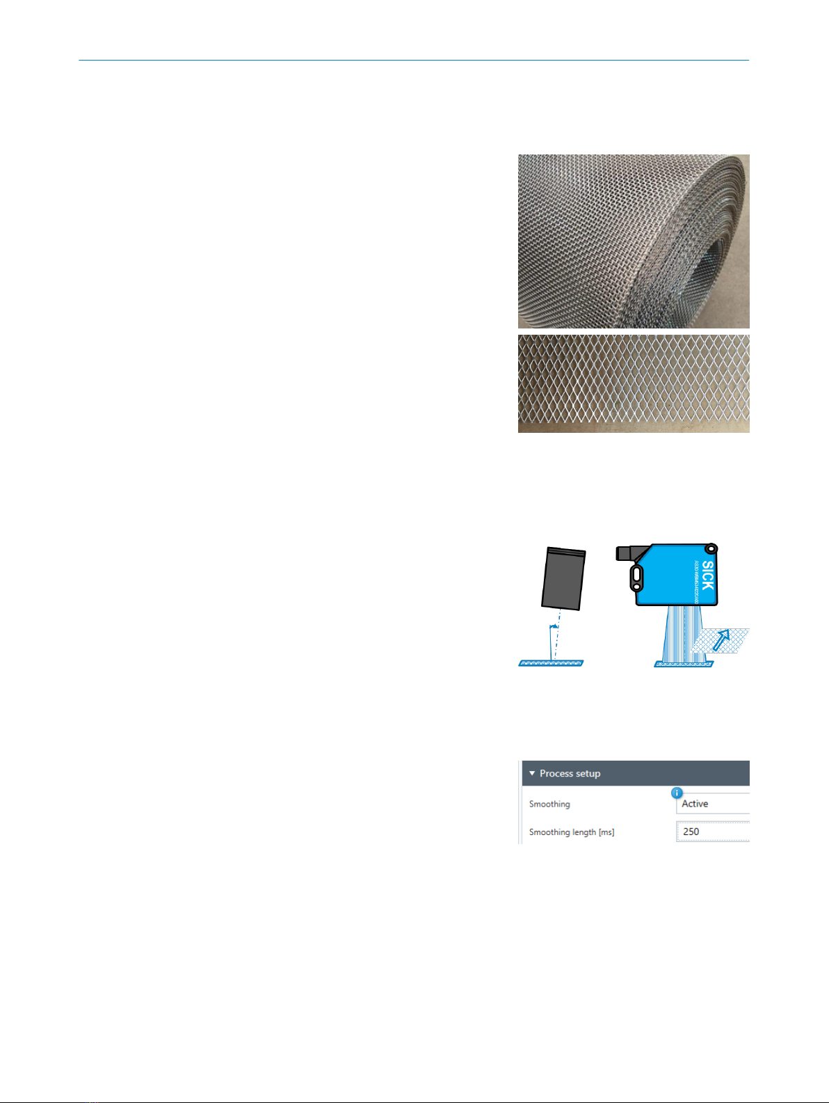
In large printing houses, the alignment
of the paper is extremely important. On
many occasions, a printing alignment
line is also used. With this line, the
paper edge and the printing edge are
both measured to ensure alignment of
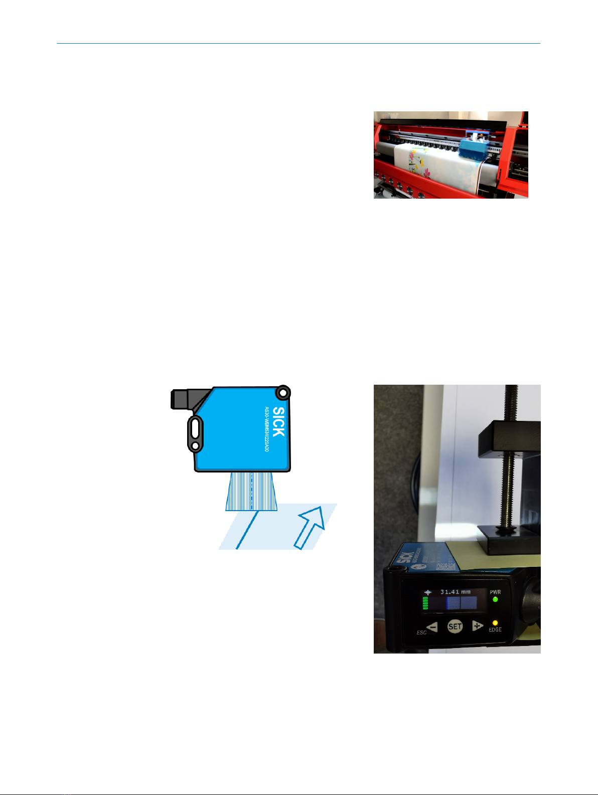
printer head and paper. Camera sys‐
tems have been used to manage this
task, but due to lighting and different
print line colors, repeated setup is
often needed. The customer requires
an accuracy of 0.1 mm with the dis‐
tance from Line to edge calibrated to
13 mm.
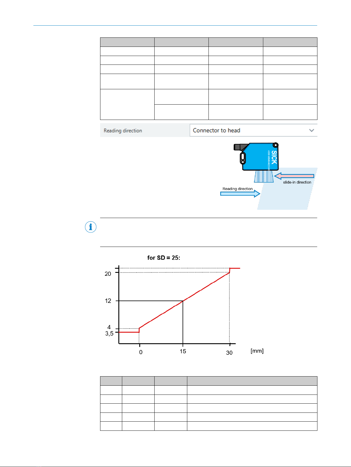
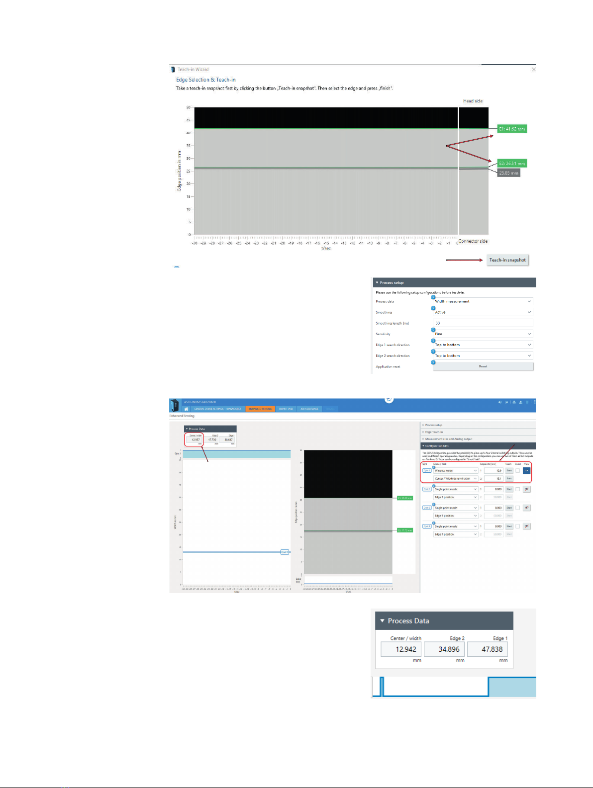
How to ... (Setup and configuration)
Using Sopas, the AS30 can be configured to width measurement. Also ensure that the
sensitivity is set to Fine.
On the target, select an Easy Teach-in to detect the first two edges in edge search direc‐
tion.
Select Advanced Teach-in to select the preferred edges.
Sopas
In the Teach-in Wizard, select the Teach-in snapshot and then select the preferred edge.
GUIDE LINE DETECTION IN PRINT INDUSTRY 4
8025153/2019-12-10 | SICK T E C H N I C A L I N F O R M A T I O N | AS30 9
Subject to change without notice